
Hello to all electronics lovers. Wireless communication is now so widespread that even manufacturers of modern smartphones manage to produce models without a headphone jack, so the sound is transmitted through a wireless network. In this article I will tell you how to make a wireless sound transmitter using IR, which in ancient times was a sensation in the development of mobile technologies. We will do it using the kit kit, a link to which will be at the bottom of the article.
Before reading a detailed description of the assembly process, I suggest watching a video where each step is clearly analyzed and a complete check of the finished kit kit is carried out.
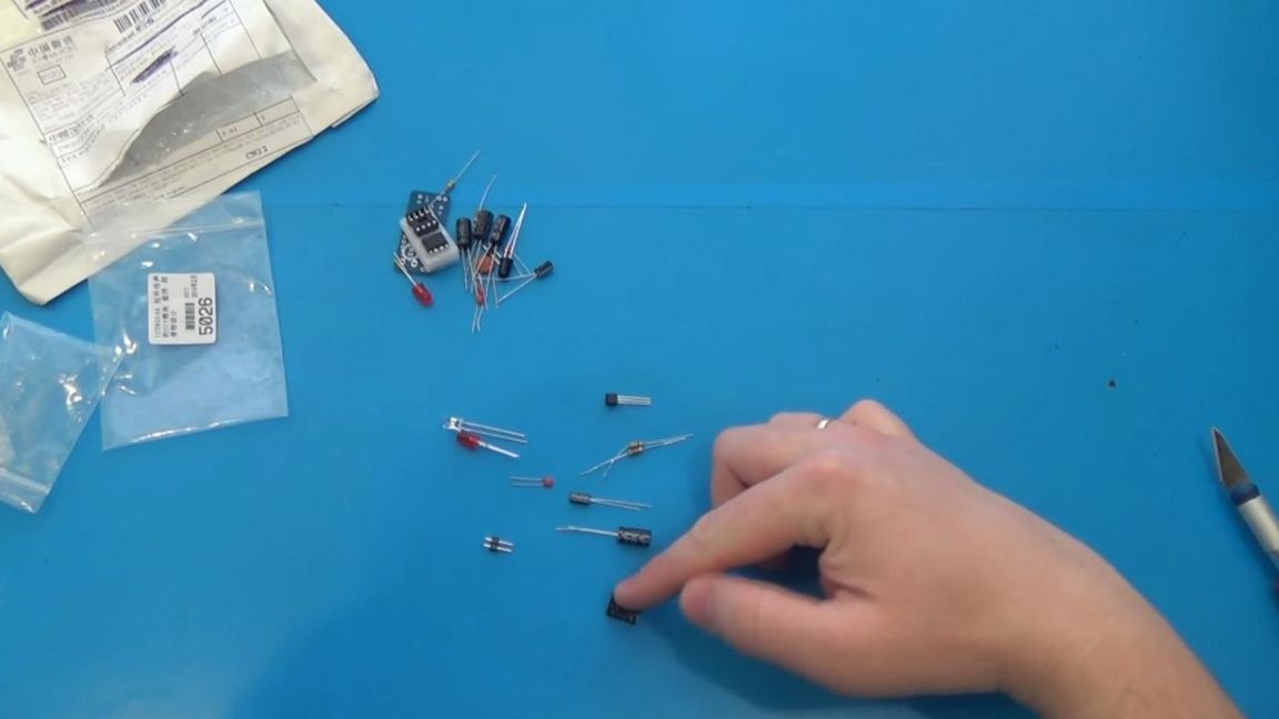
To make an IR sound transmitter do it yourself, you will need:
* Kit
* Soldering iron, solder, flux
* Side cutters
* Device for soldering "third hand"
* Speaker
* A sound device, in this case a telephone
* A couple of wires
* Multimeter
Step one.
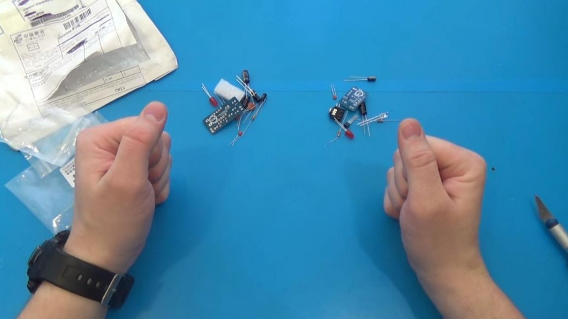
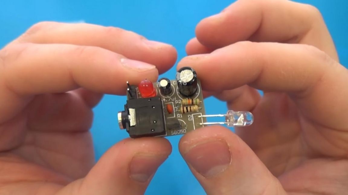
First you need to arrange all the components on the board.
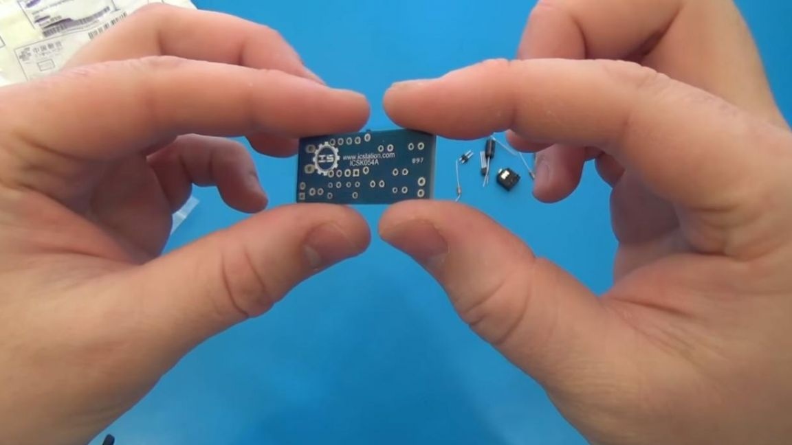
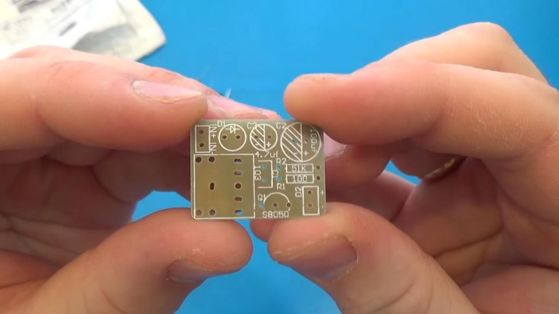
First, we place the resistors on the board, but before that we need to find out their value.
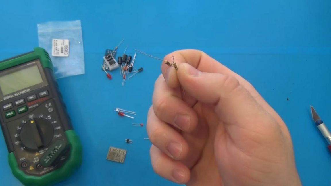
In order to determine the values of resistors, there are three ways: using a multimeter, a look-up table and a resistance calculator. The first method will be faster and more convenient, but if you do not have a multimeter, then you can also assemble a circuit without it, but it will take a little longer.
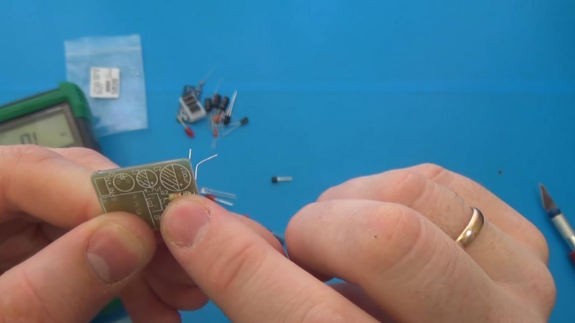
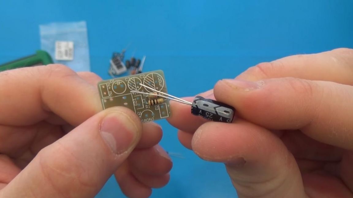
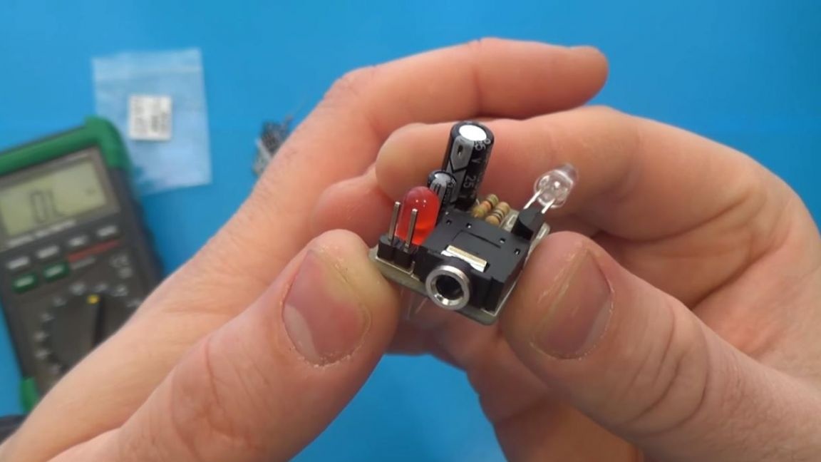
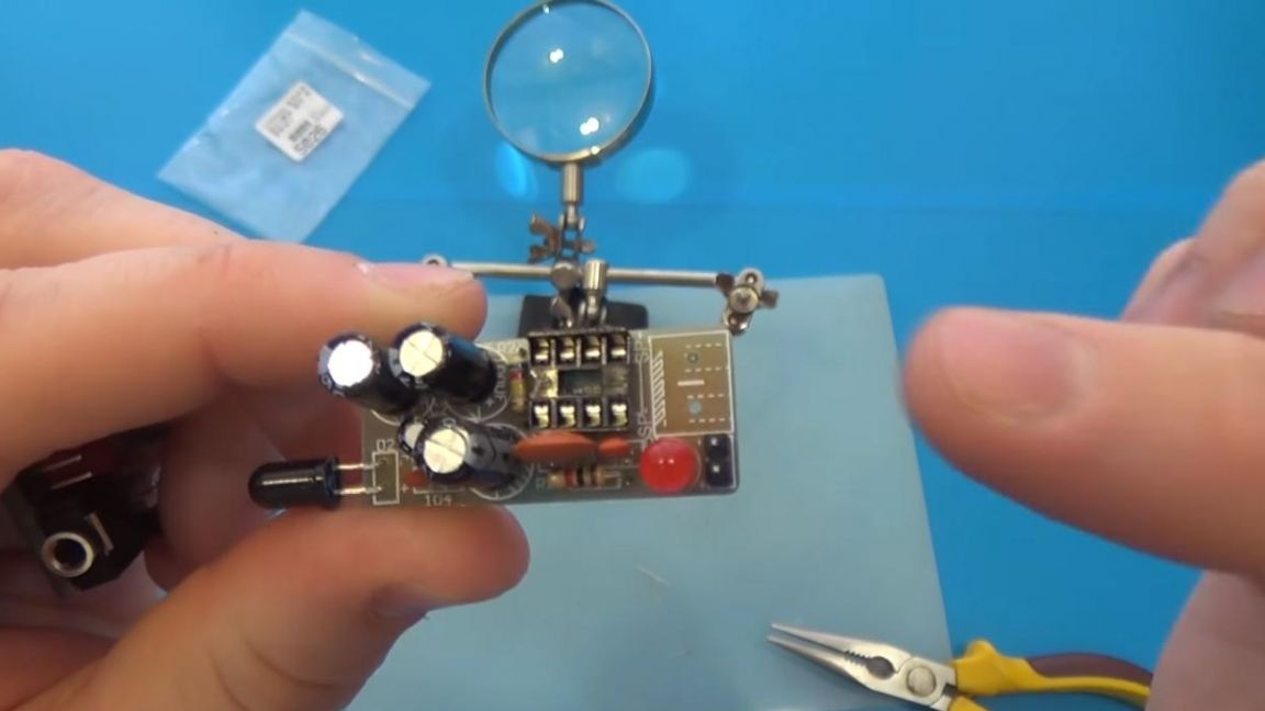
After the resistors, we install capacitors on the board, there are only two of them on the transfer board, and their capacitance and voltage are signed. It is also necessary to observe the polarity during installation, the long leg is the plus terminal, and the short one is minus, the minus sign on the board is shaded.
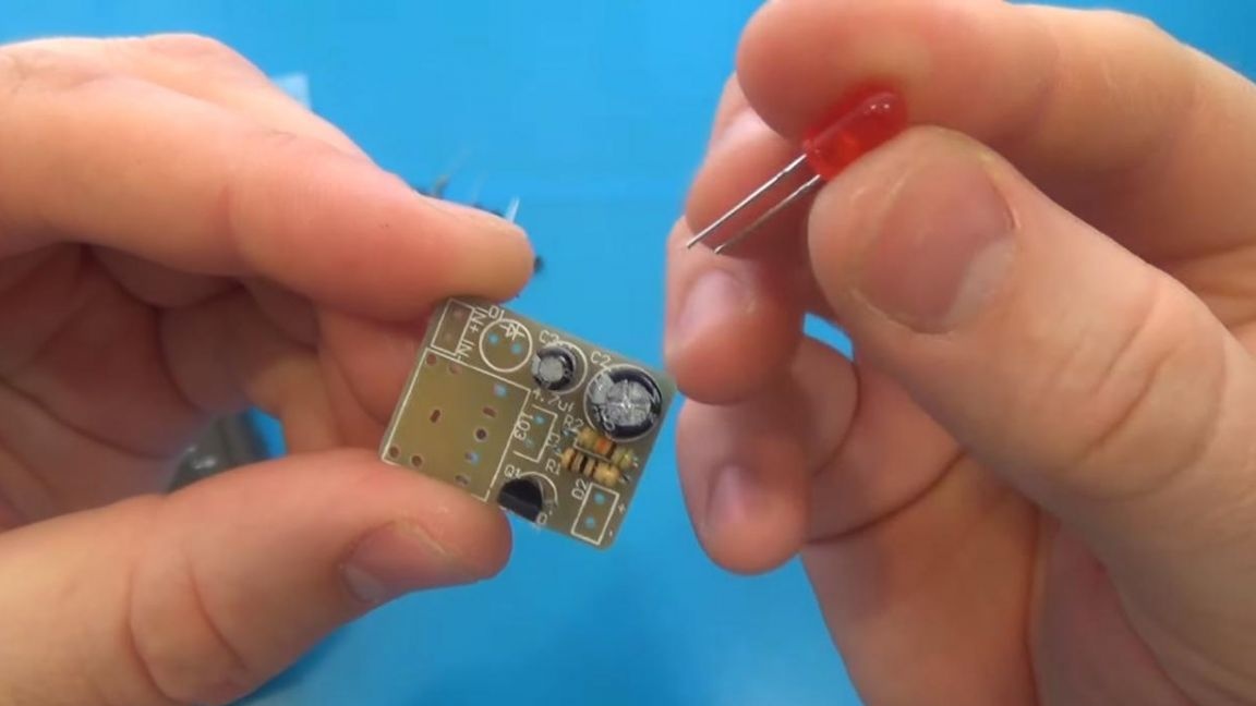
The same principle in the installation and with LEDs, only in this case the triangle with a dash is indicated on the board, and so on the dash side and pretend to be a negative contact.
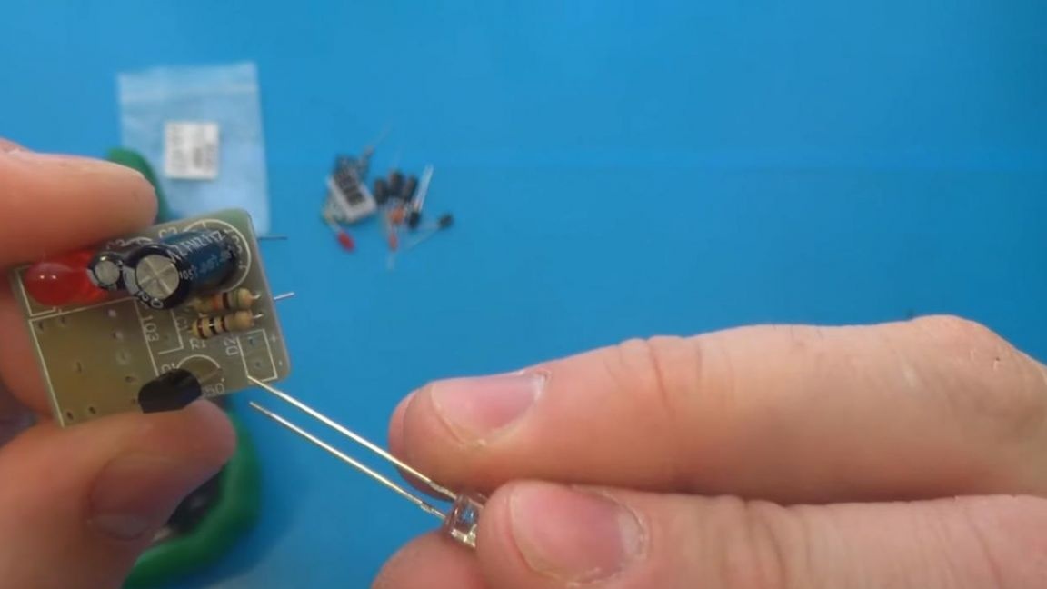
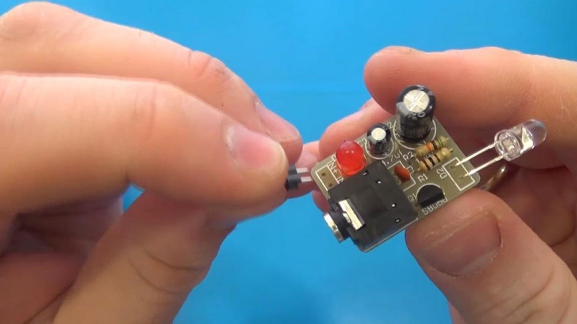
Next, we place the ceramic capacitor on the board, according to the marking on its case and the inscription indicated on the board, after which it remains to put a 3.5mm jack for audio transmission using the AUX cable, as well as establish a couple of contacts that will be connected to the power supply.
When all the components on the board are installed, go to their soldering.
Step Two
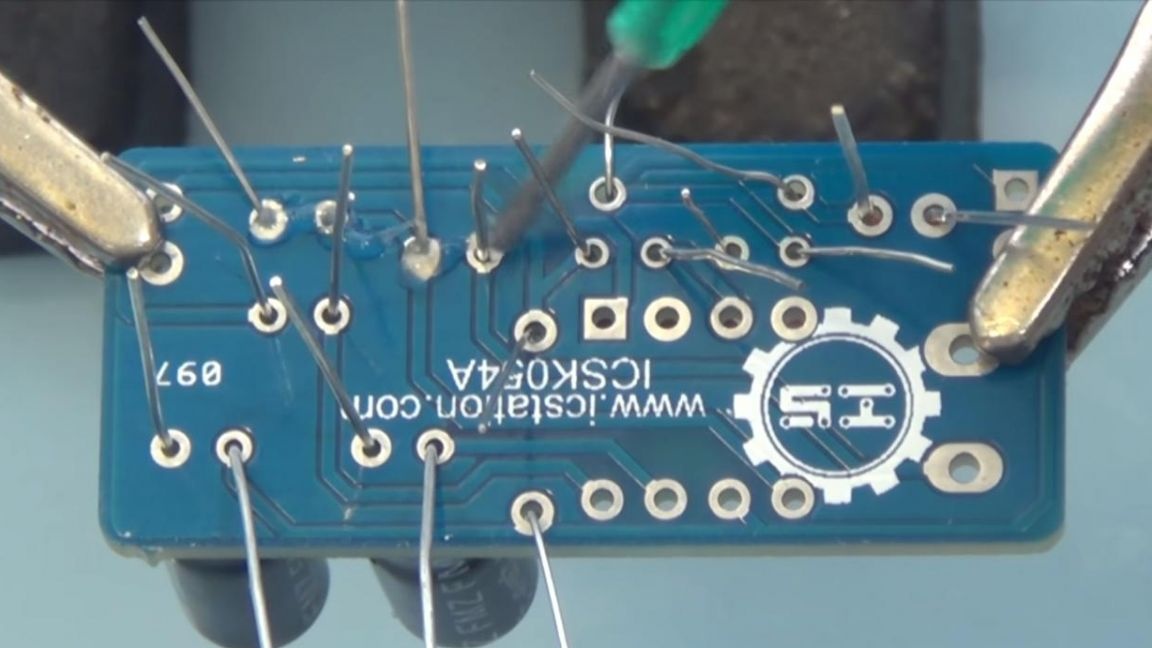
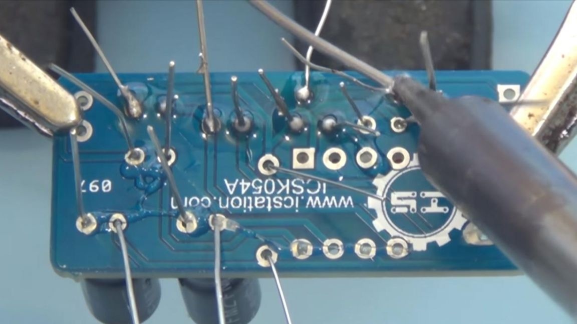
We fix the board in the soldering device "third hand" and with a slight movement of the soldering iron we tin the contacts and solder each output of the component, do not forget to apply a little flux before soldering, which will significantly improve the soldering process.
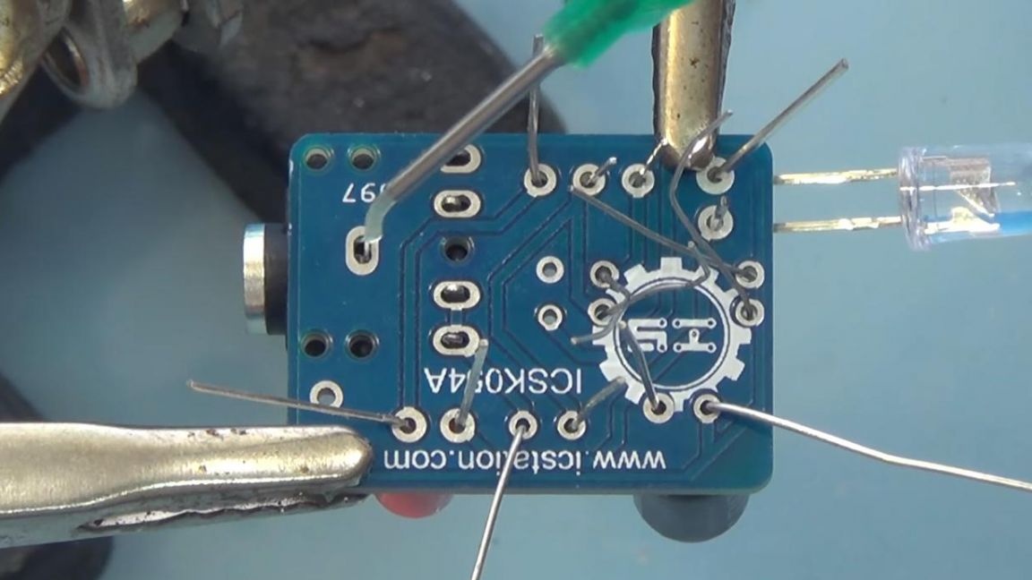
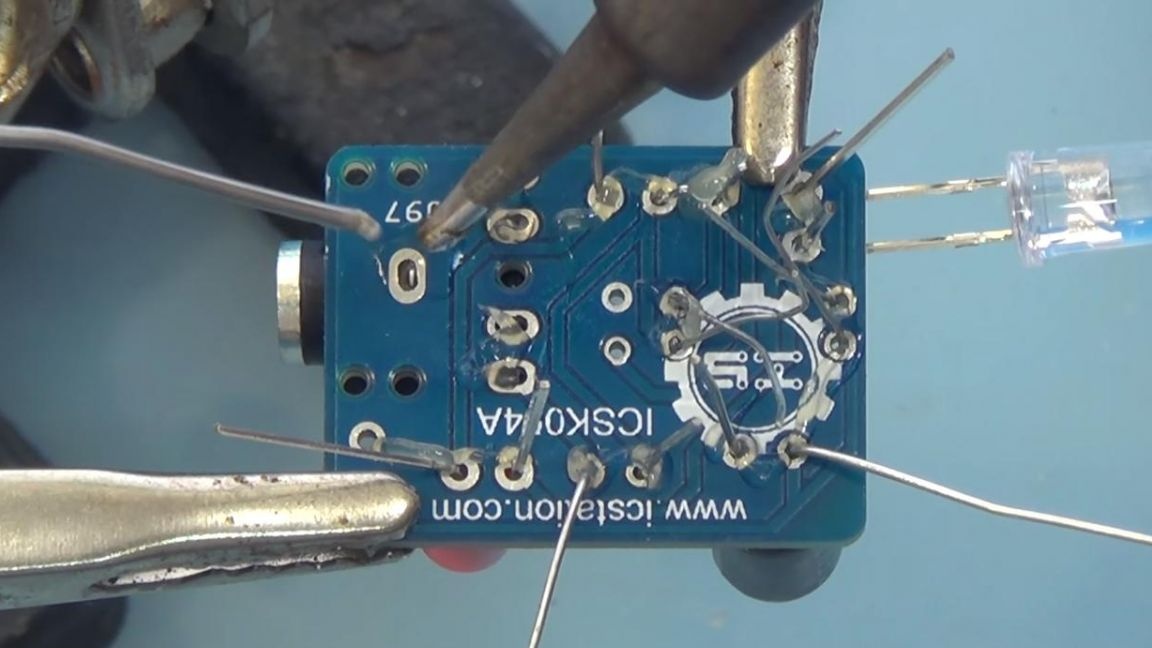
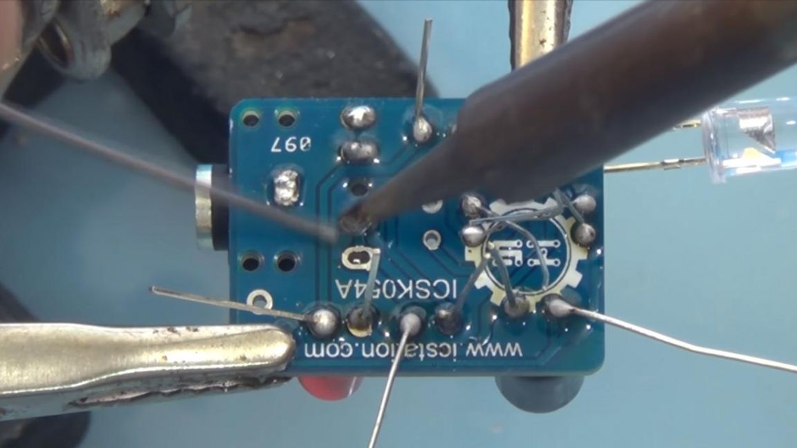
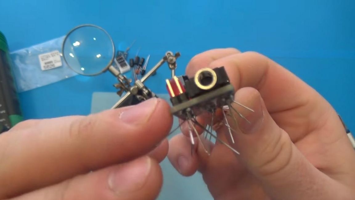
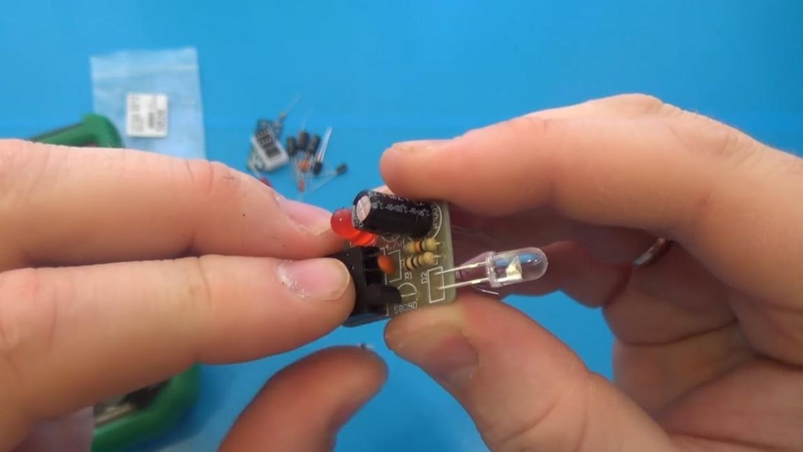
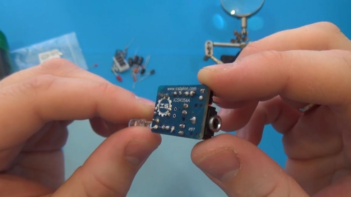
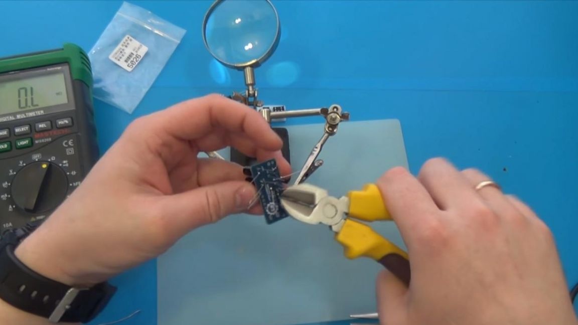
This is how the board looks after soldering, we remove the remnants of the conclusions with the help of side cutters, while being careful, as you can accidentally tear out a copper path with "roots".
Step Three
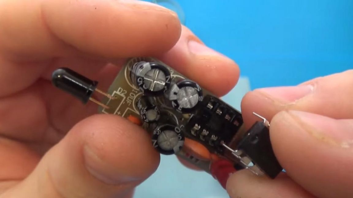
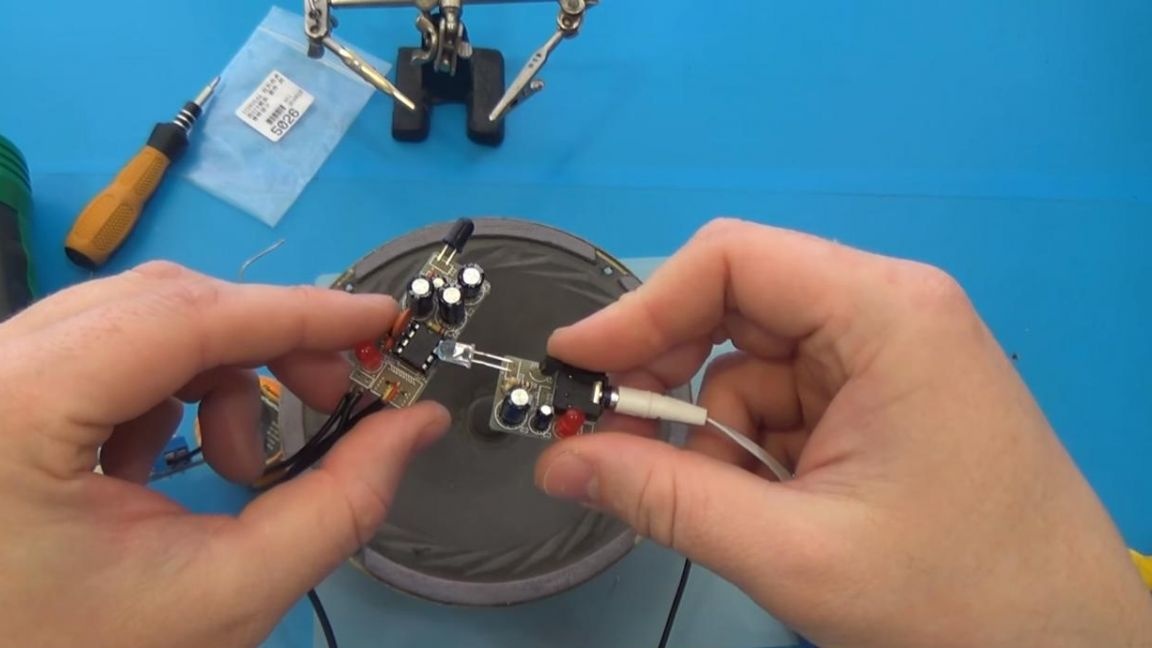
Now we turn to the sound-receiving board, its dimensions are slightly larger than the previous one. Similarly to the first board, we arrange the components, since everything is signed on it.
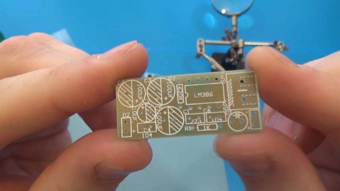
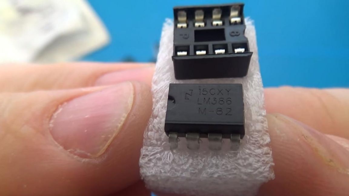
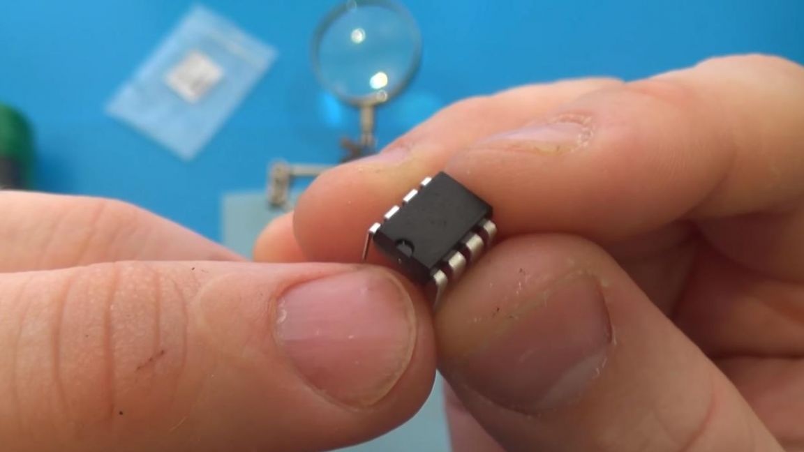
There are a bit more components here, and there is also a place for installing a microcircuit, namely LM 386, which in turn is an amplifier.
We also apply flux to the places of soldering and soldering, timely adding solder to the board, but do not overdo it, since you can connect the contacts together, which will take a lot of time for editing.
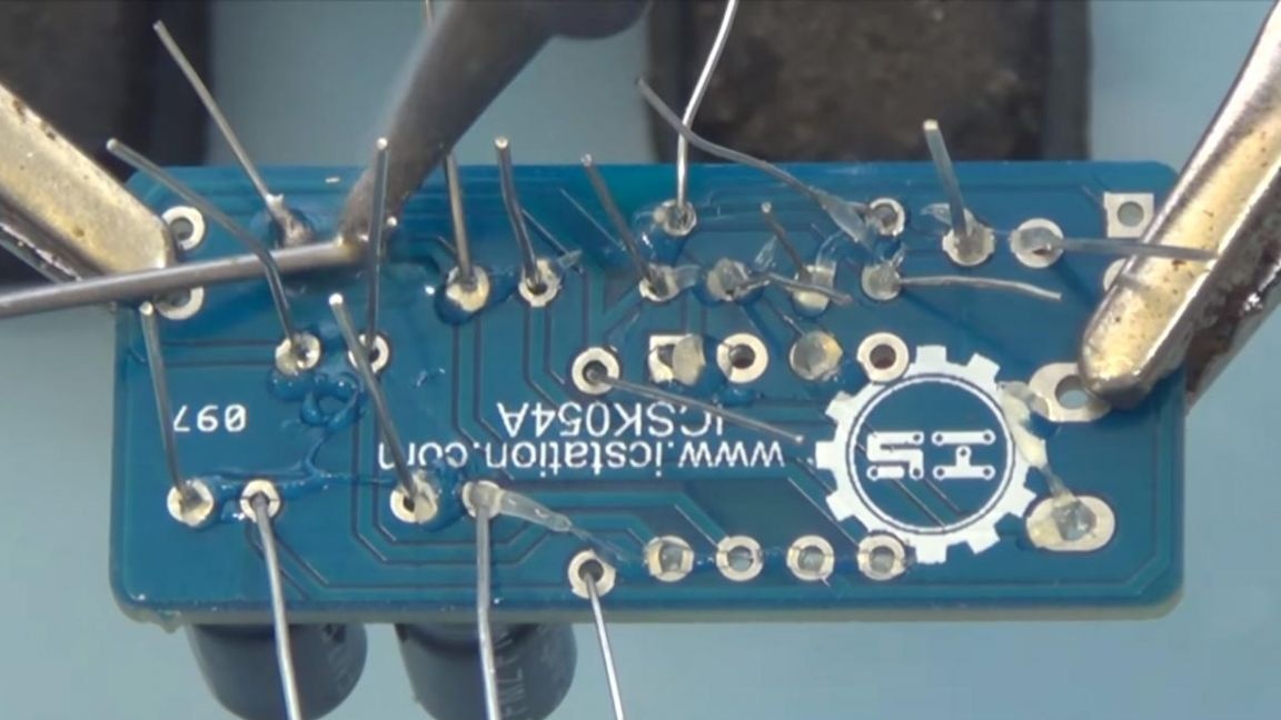
After all the components are soldered, remove the remnants of the findings using side cutters.
We clean both boards from flux to eliminate unwanted distortions, as well as improve the appearance of the board. We install the microcircuit on the board, we compare the key on the case with what is located in the slot on the board.
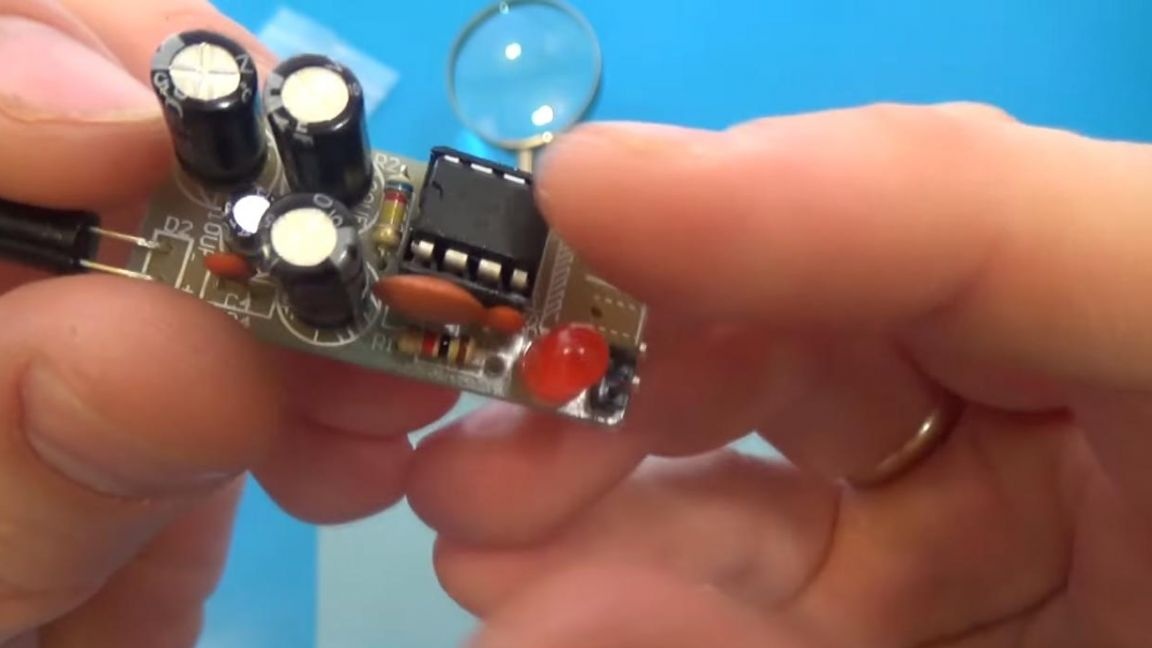
It remains to solder the power wires and you're done.
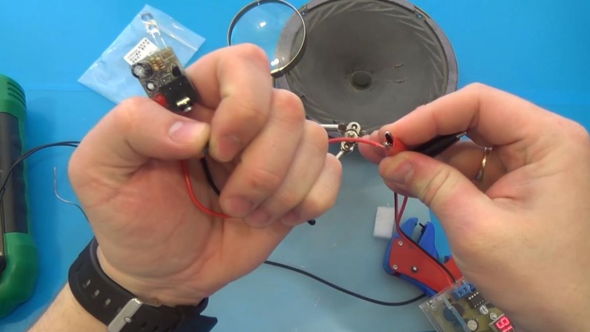
For power, you need two wiring, solder them according to the polarity and connect to the power supply.
Step Four
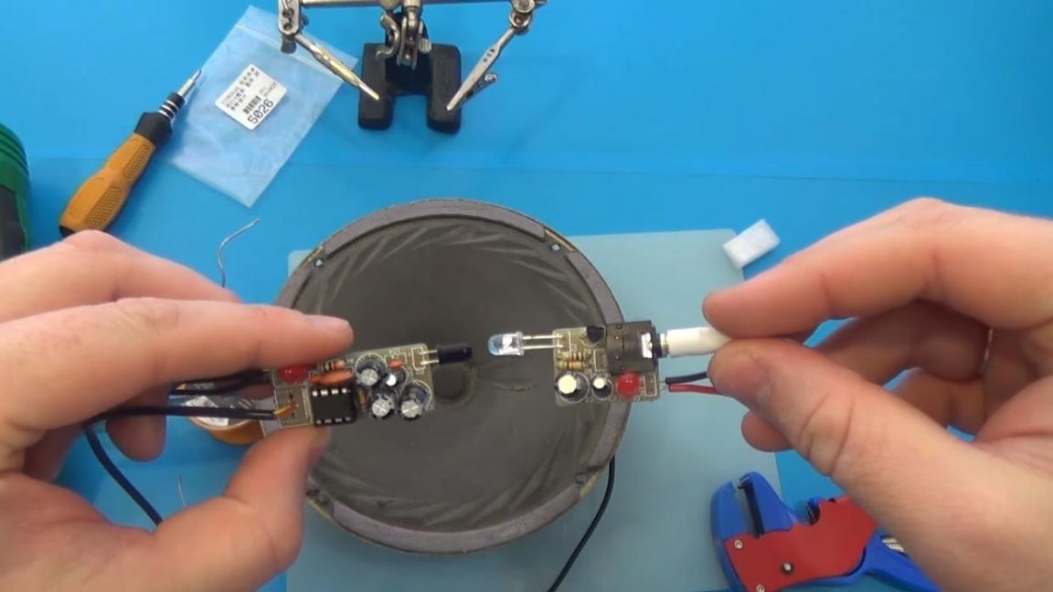
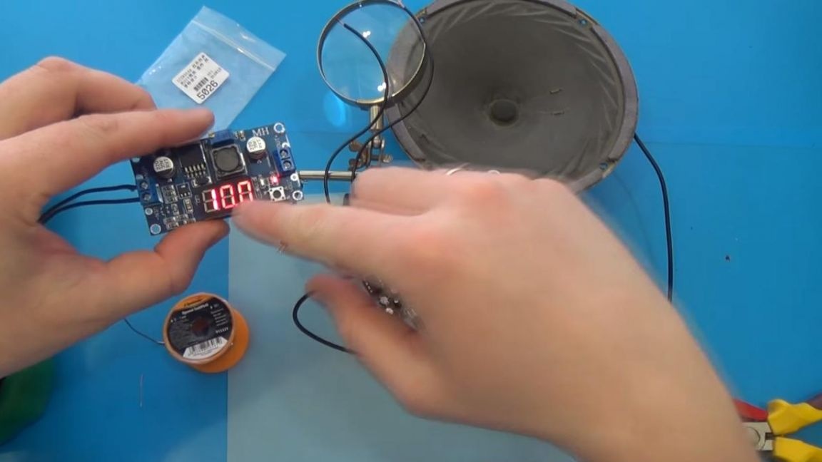
It's time to test the kit in practice, we connect the wires to the power supply, the maximum voltage for both boards is not more than 12 V.
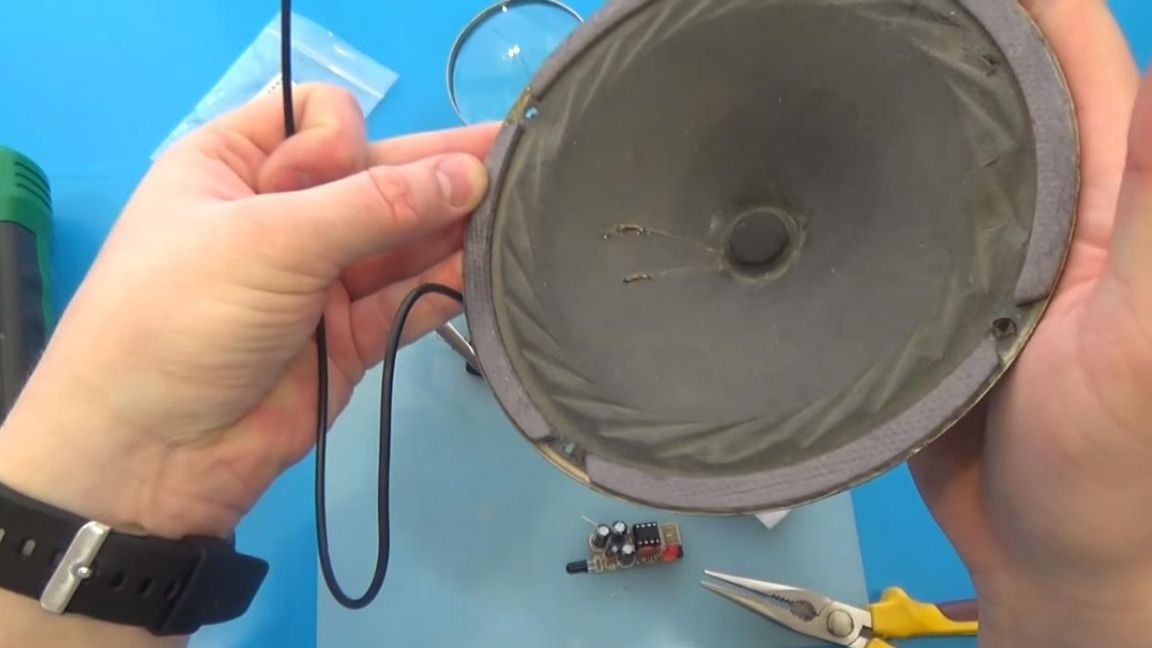
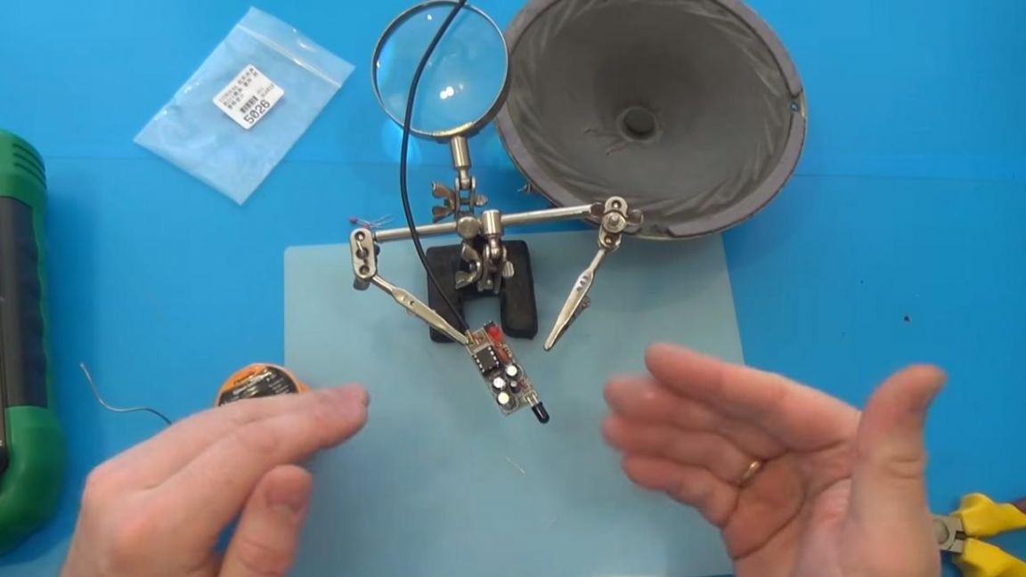
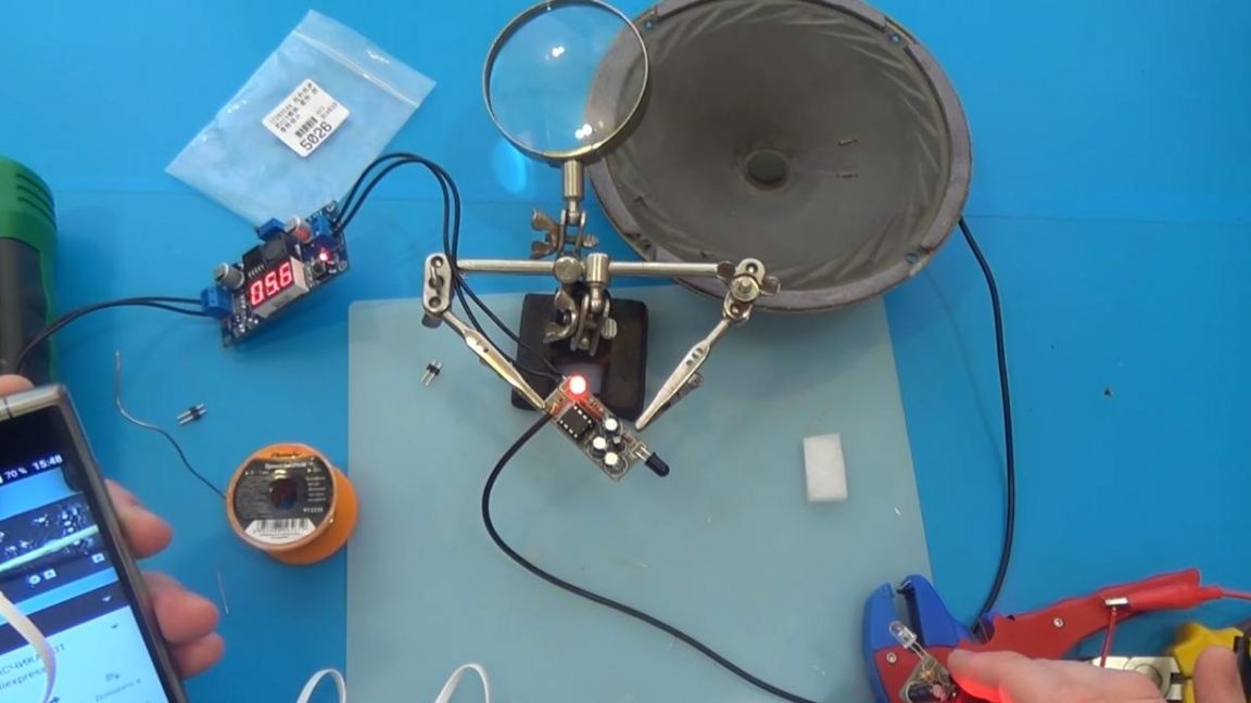
We connect the phone to the transmitting board using the AUX cable, and we connect the speaker to the receiving board. With direct hover of boards relative to each other, the sound is heard clearly and without distortion.
That's all for me, thank you all for your attention and creative success.