
Hello to all electronics lovers. Probably everyone knows that the voltage in the outlet is 220 volts, but sometimes it becomes necessary to adjust this voltage, for example, to dim the light bulbs or reduce the number of engine revolutions. In this article I will tell you how to make a dimmer for regulating the voltage from a 220 V network using a kit kit, a link to which will be at the end of the article. Such a dimmer will help in your electronic homemade, for example, it is useful where you need to change the frequency of rotation of the electric motor or change the brightness of the lamp or other devices operating on a voltage of 220 V, its maximum power is 2000 W, but I do not advise using it at maximum, since the efficiency will be lower , and the device itself is pretty hot.
Let's proceed to the assembly.
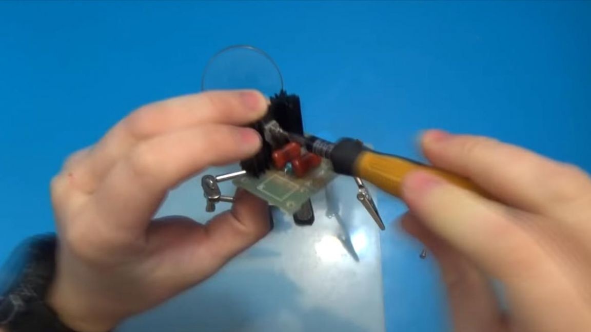
Before you start reading a detailed description of the assembly process, I suggest watching a video that shows the operation of the finished kit kit and the visual manufacturing steps.
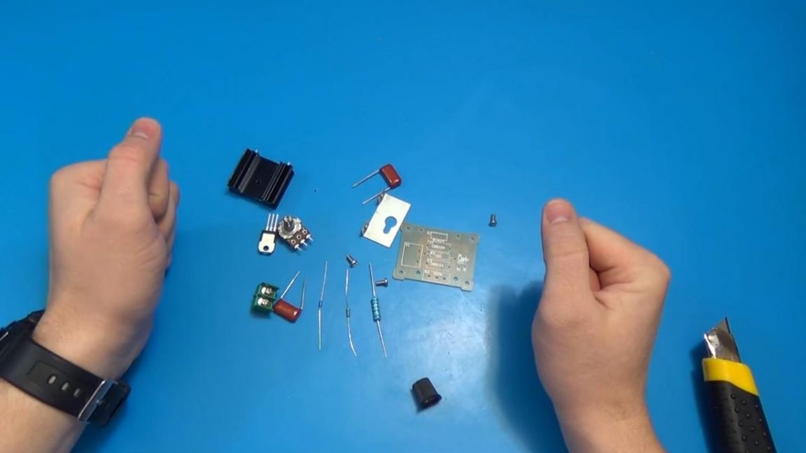
To make a dimmer do it yourself, you will need:
* Kit
* Soldering iron, solder, flux
* Side cutters
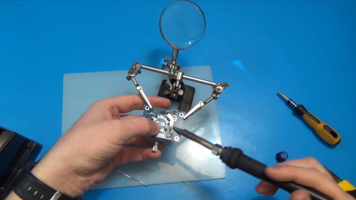
* Device for soldering "third hand"
* Bulb of any power, powered by 220 volt network for testing
* A pair of wires
* Multimeter
Step one.
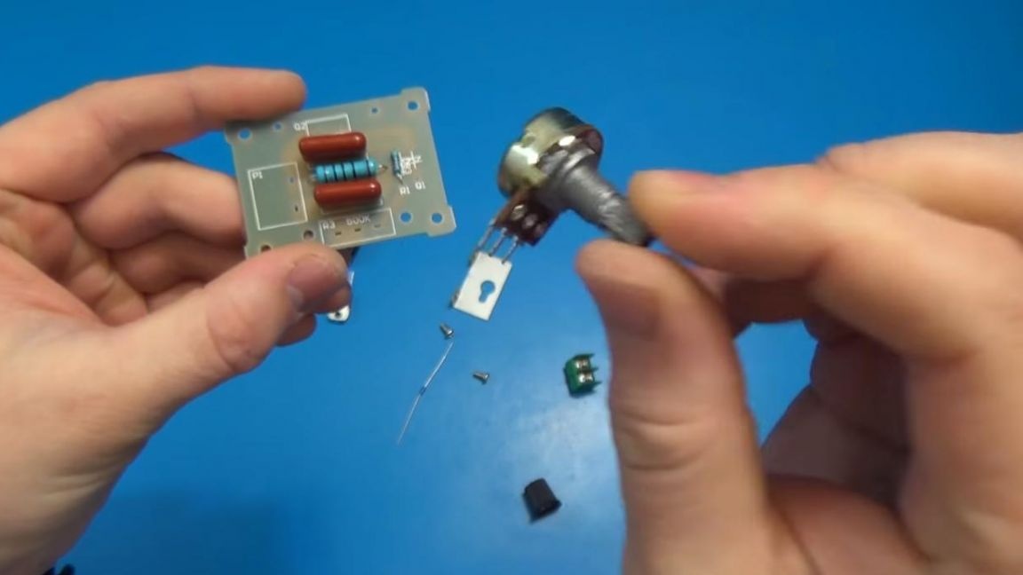
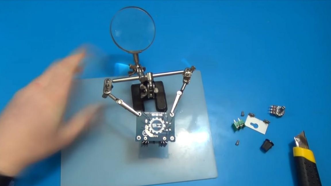
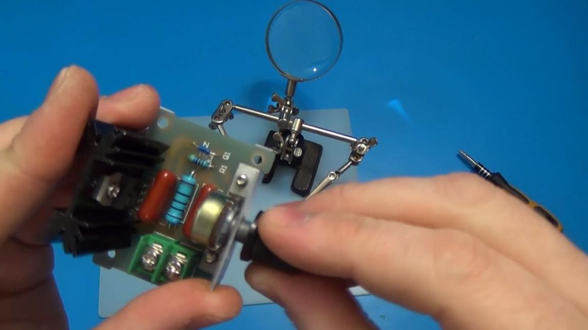
The first thing in assembling this dimmer is the location of the components on the board. The dimensions of the board are quite compact, which will be a significant advantage when installed in a small case.
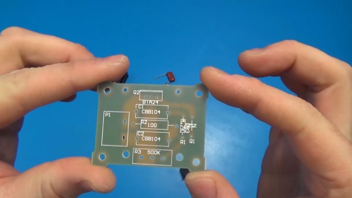
We install the resistors in their place, there are three ways to determine their values: using a multimeter to measure their resistance, a look-up table on the Internet for color marking or a resistance calculator, where the color is individually selected and the resistance value of this resistor is displayed. Of course, the first method will be much faster and more convenient than others, but if you don’t have a multimeter, then there’s nothing wrong with that, you can build a circuit without it, only it will take a little more time. In this circuit there are only three resistors, we measure their resistance by any convenient method for you and install it on the board by slightly bending the legs on the back side.
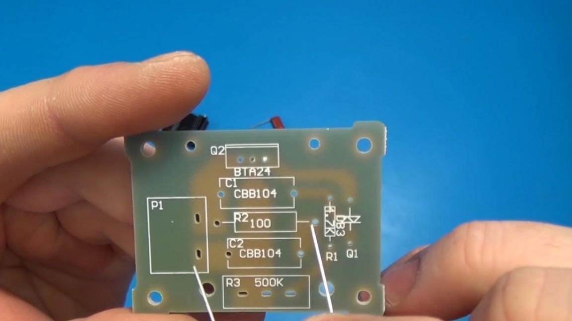
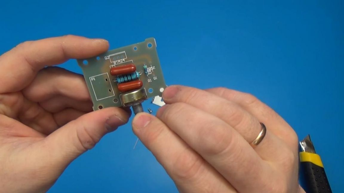
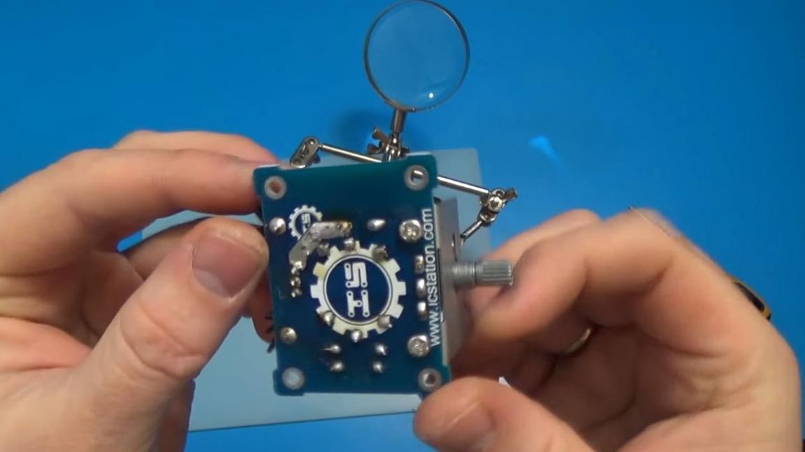
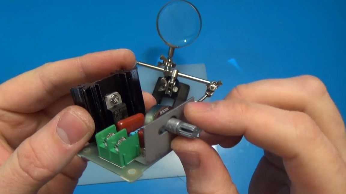
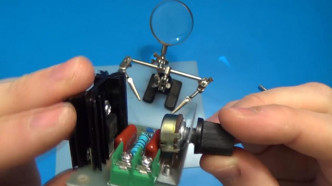
After installing the resistors, we put ceramic capacitors, there are two of them and their values are indicated on the board. Also, do not forget to install the diode, its marking is shown on the board, for correct assembly it is simply necessary to combine the strip on the diode with that shown on the board.When the capacitors are installed, we turn to a 500 kΩ variable resistor, with which the output voltage will be changed by rotating its handle, three contacts are highlighted on the board under it, it will not be possible to mix them up in places.
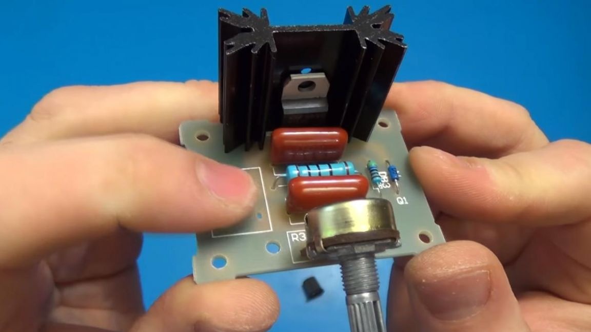
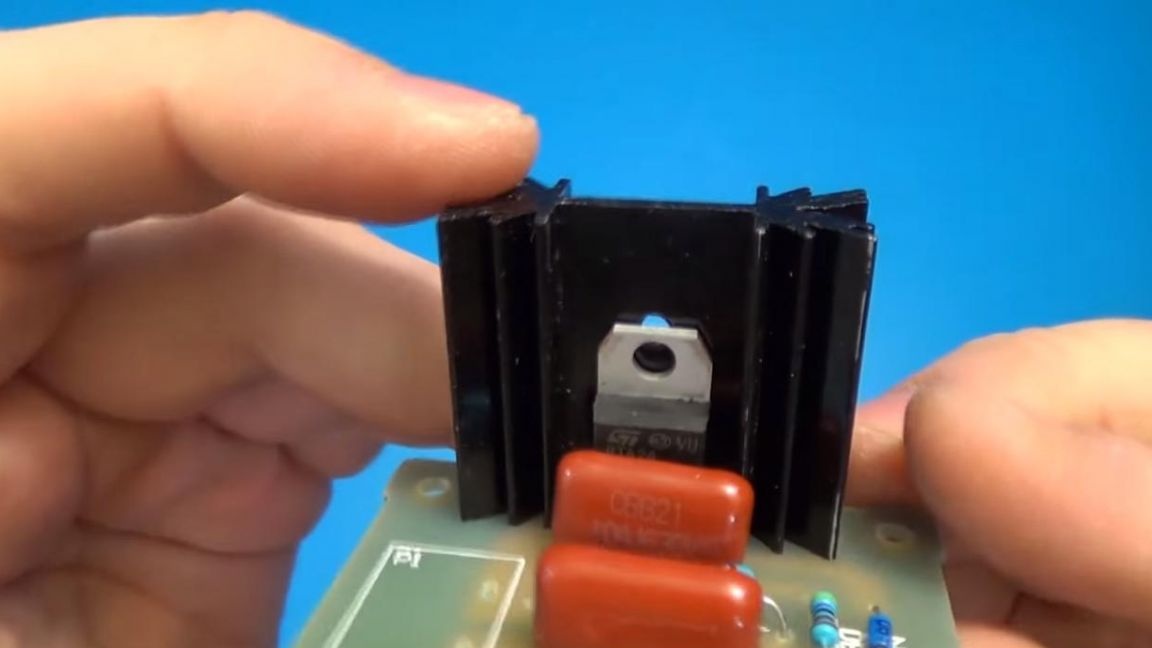
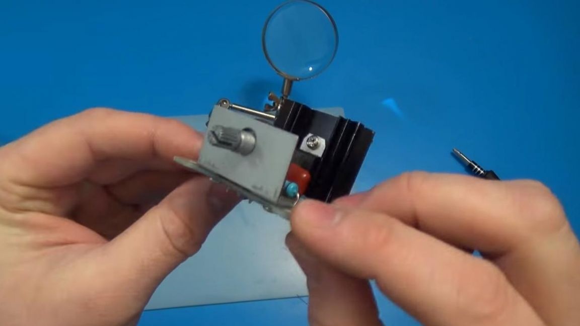
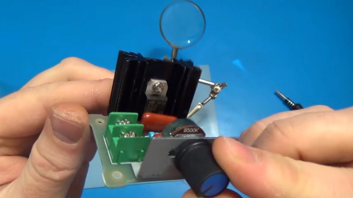
Next, we install a cooling radiator and a transistor, which can immediately be bolted to the radiator body.
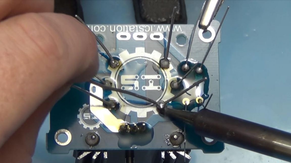
Step Two
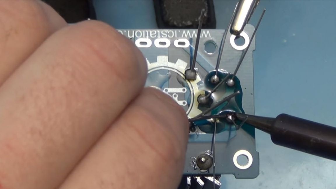
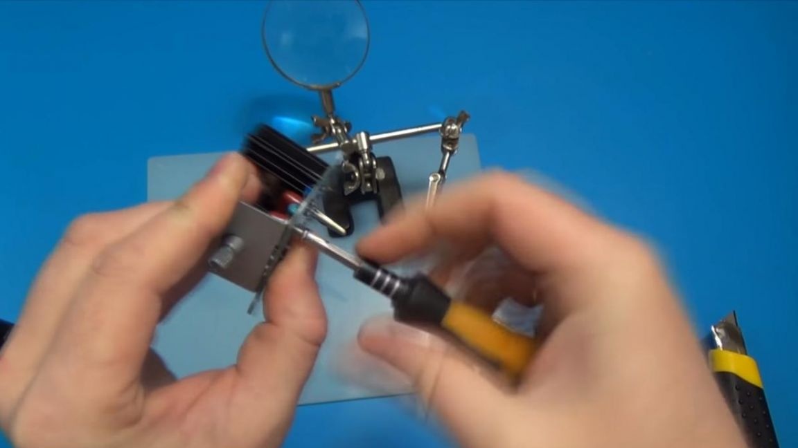
That's all the components on the board are put in their places, it's time to solder. We plug the soldering iron into the socket and securing the board in the soldering device "third hand", solder the conclusions to the contacts on the board.
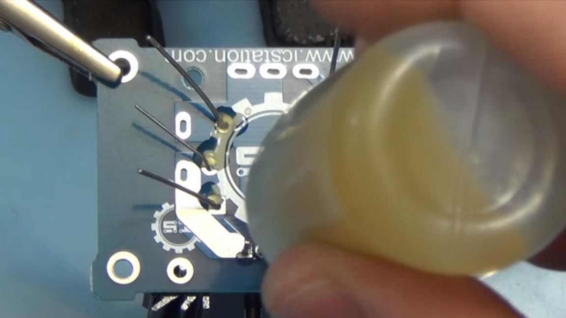
For better soldering, a flux must be applied in advance.
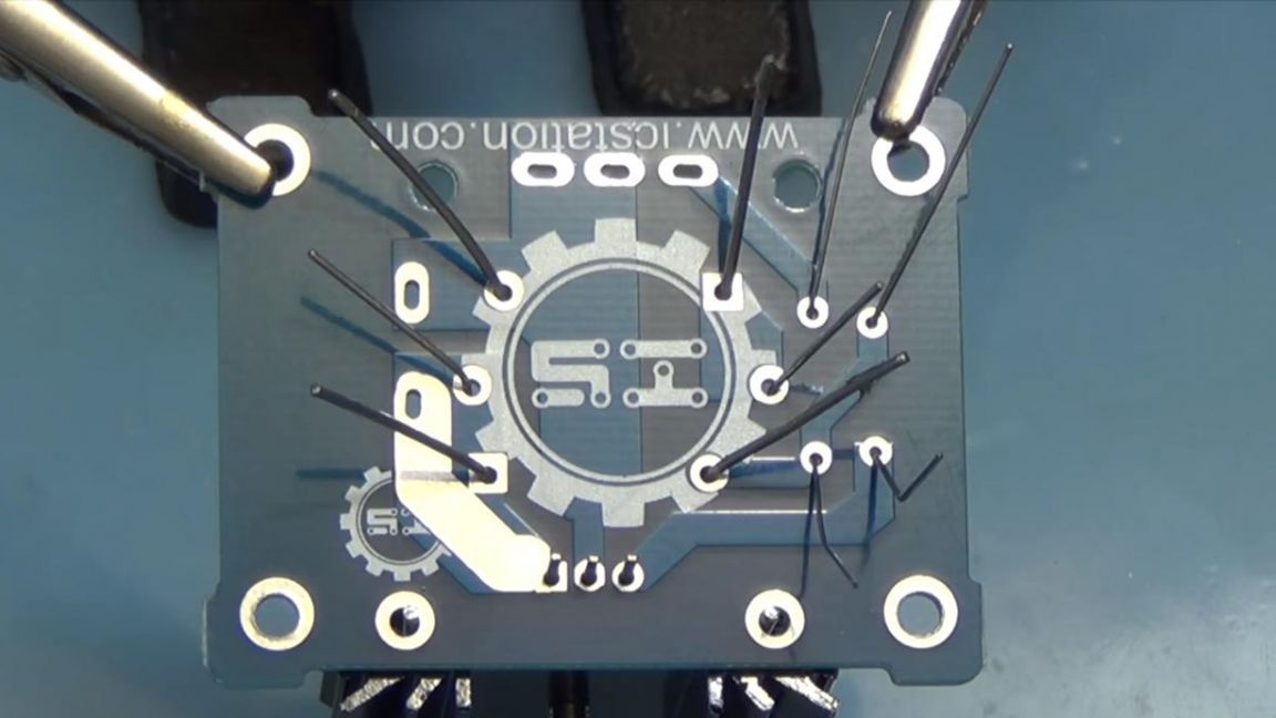
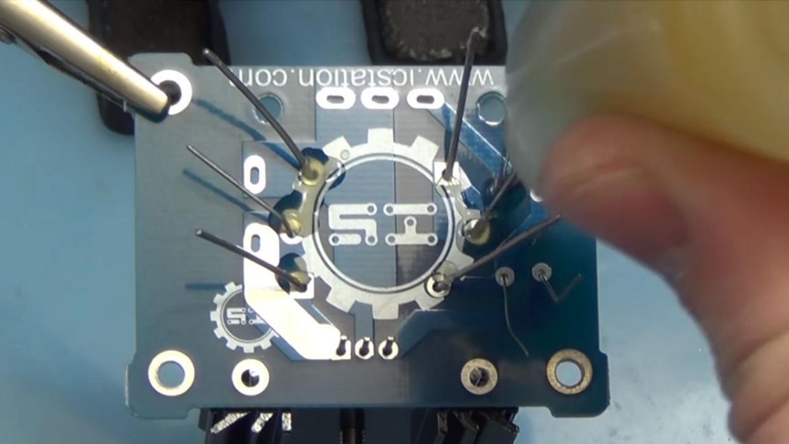
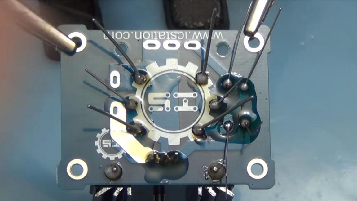
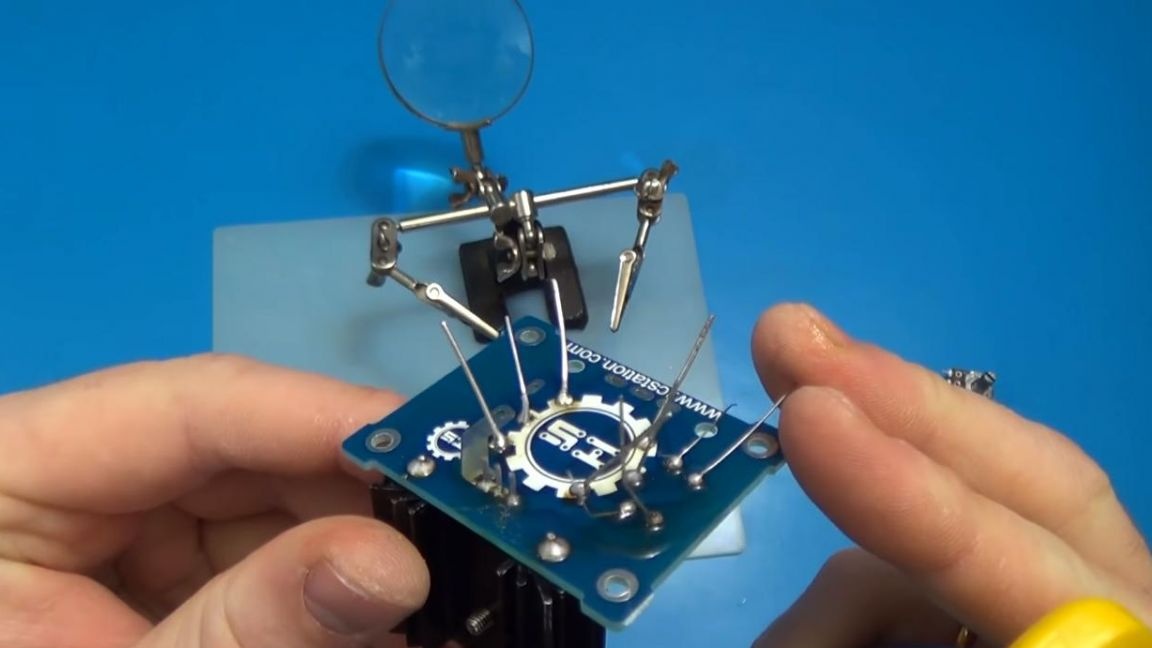
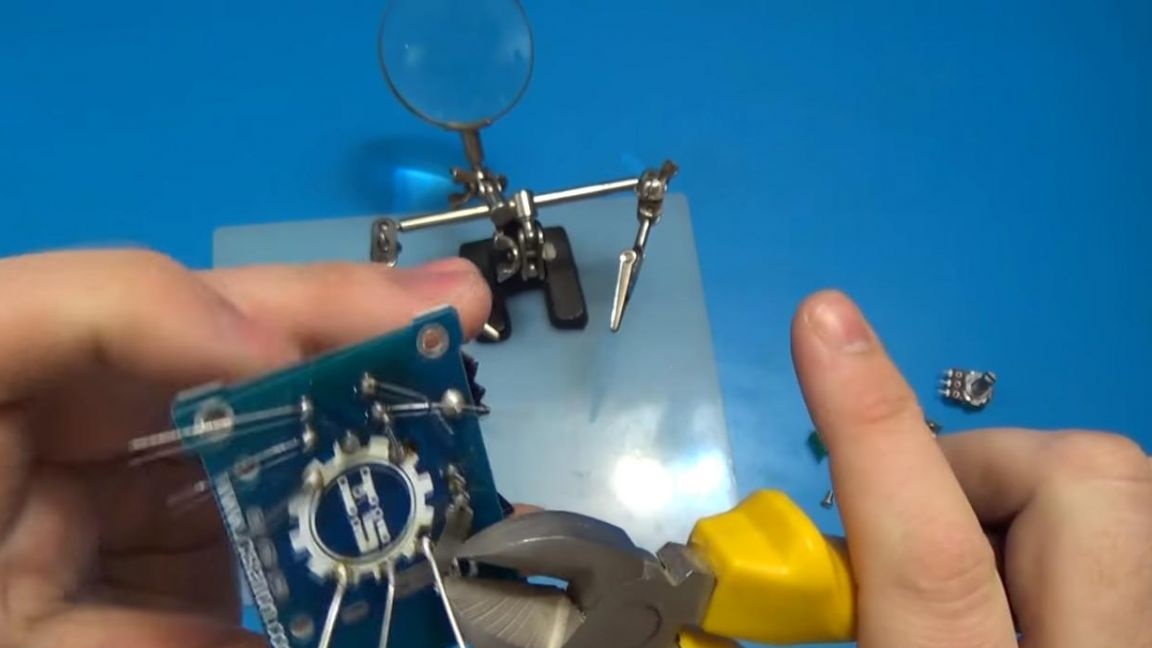
After soldering, you need to remove the remnants of the conclusions using side cutters, only be careful in this operation, since you can easily damage the tracks or even tear them out with “roots”, then wash off the excess flux with a solvent, for example, galosh gasoline.
Step Three
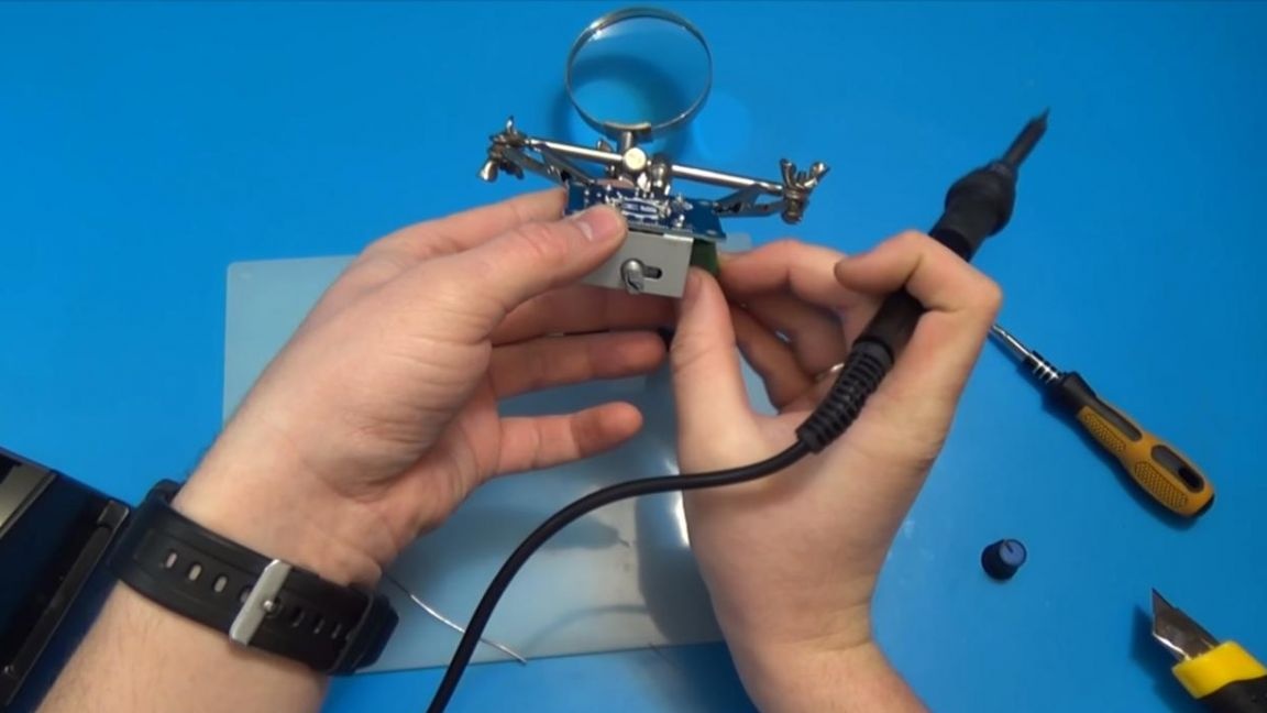
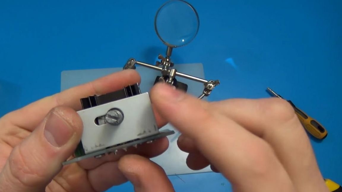
After removing the excess terminals, solder the remaining elements, namely the terminals where the necessary device will be connected, the voltage on which you need to adjust and screw the metal plate to the board, a kind of additional fastening of the variable resistor, which will help prevent the legs from breaking when dropped or pressed hard.
Step Four
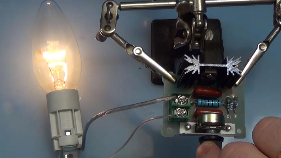
Well, this is where our device for voltage regulation is ready, it's time to move on to testing.
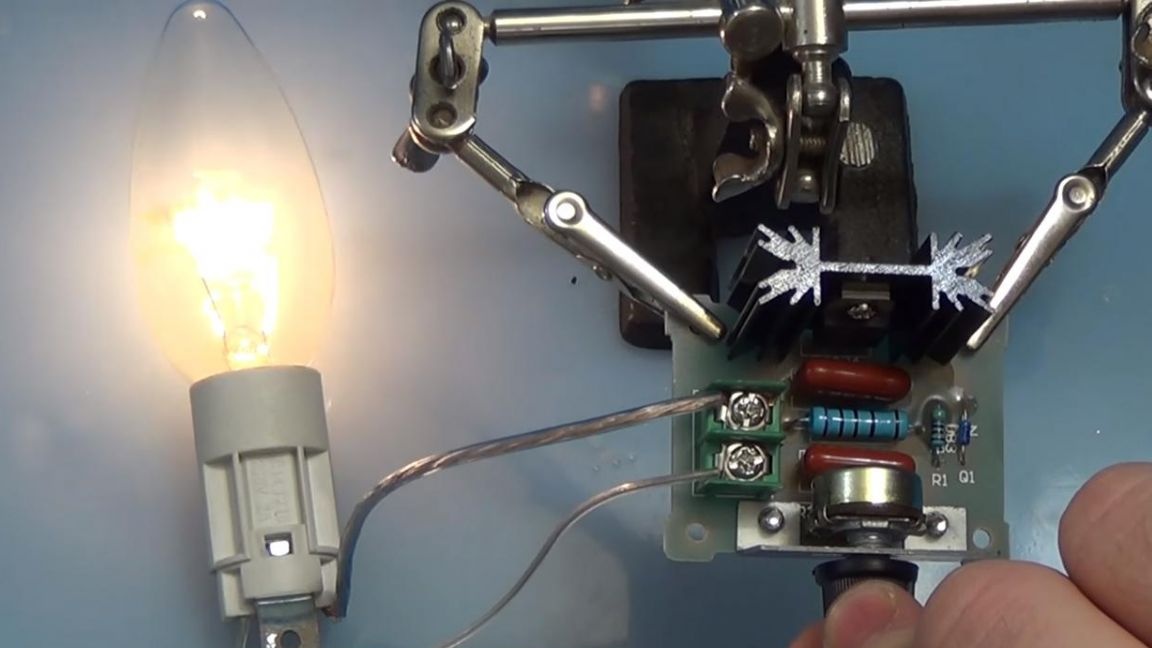
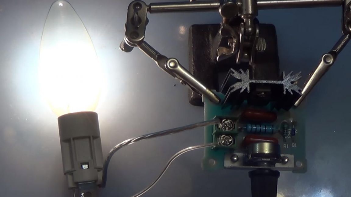
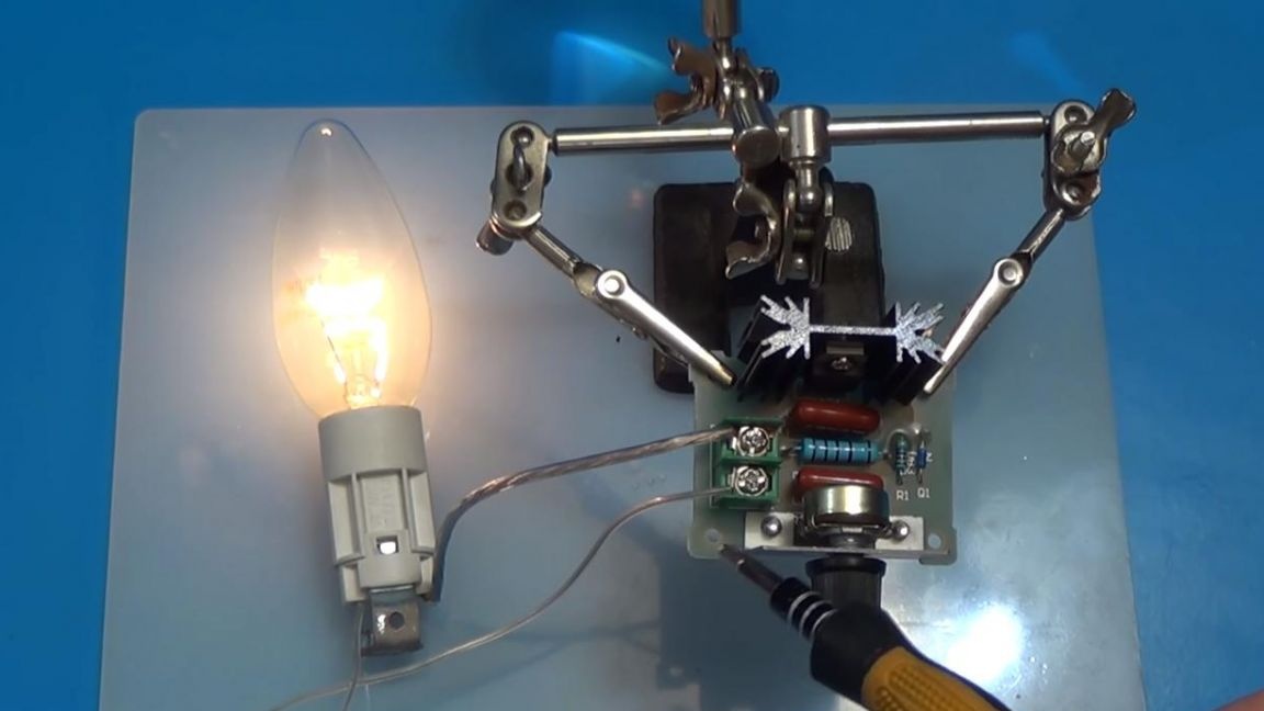
We connect the wires to the regulated voltage output using a dimmer and plug the device into a power outlet, be careful not to put your fingers in the components located on the board.
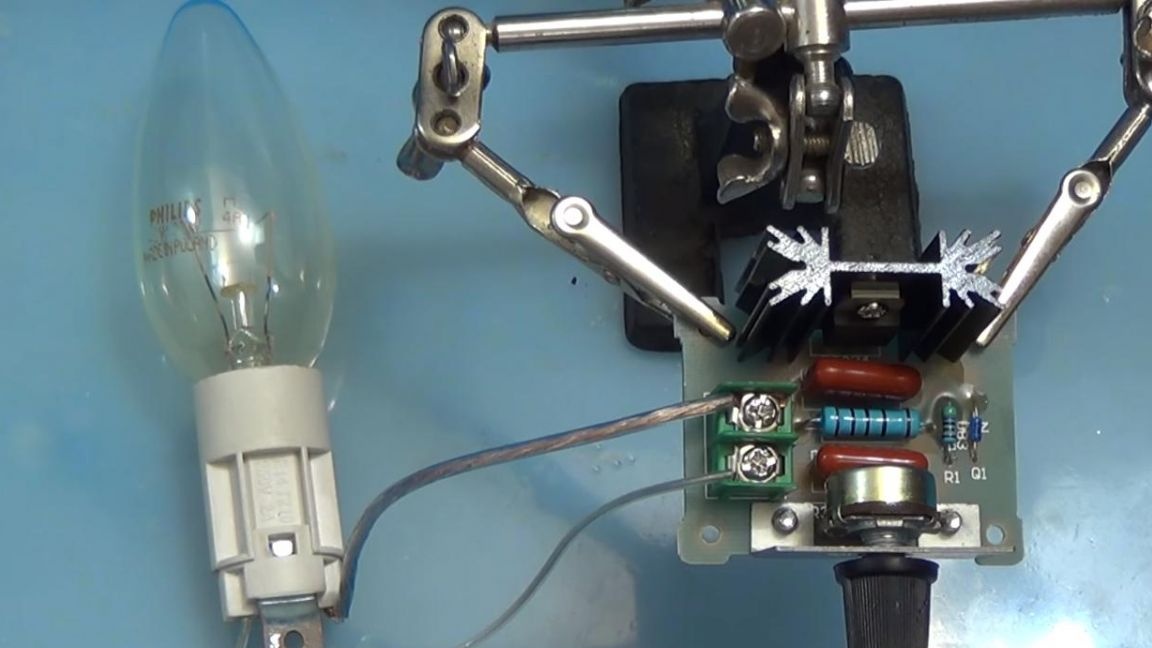
When the knob is rotated, it can be seen that the voltage at the output changes, the glow of the lamp is adjustable from zero to maximum, which is very convenient, let me remind you that the device is designed for a maximum power of 2000 watts.
That's all for me, this device can be used anywhere, and the mounting holes on the board will be just the way to put this board in the body of any homemade product.
Thank you all for your attention and successful assembly of kit-kits.