
Hello to all electronics lovers. In this article I will tell you how to make a marquee do it yourself using the kit kit, the link to which will be at the end. Assembling kit kits is a very interesting activity, so I’m sure that radio amateurs will appreciate it, since they have already assembled more than a dozen radio designers, as they were called before.
We proceed to the assembly of the kit.
Before proceeding to read the article, I suggest watching a video that clearly shows the step-by-step production and verification of a ready-made kit.
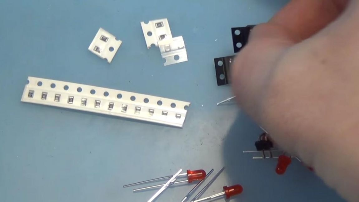
In order to make a running line on LEDs with your own hands, you will need:
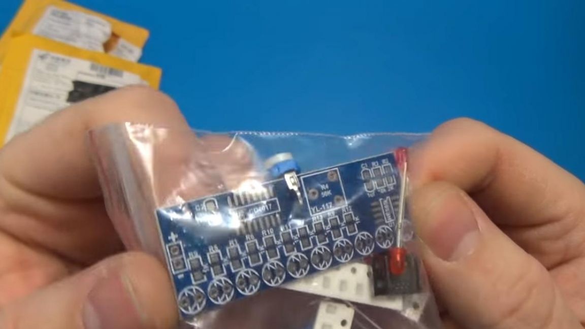
* Kit
* Soldering iron, solder, flux
* Side cutters
* Solder paste, you can buy
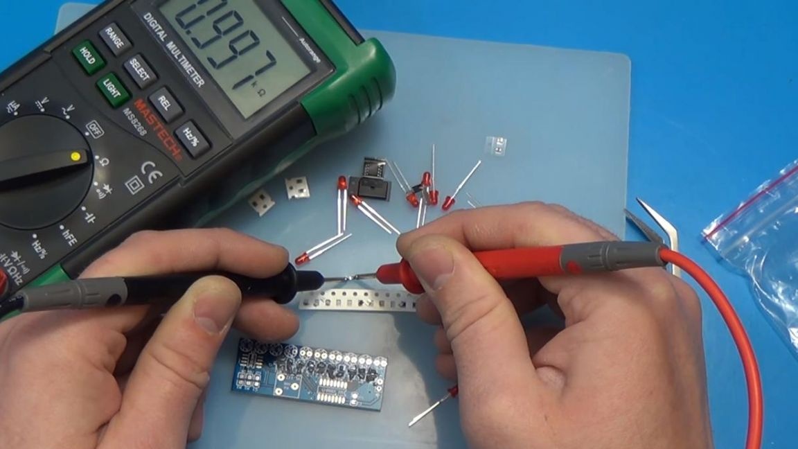
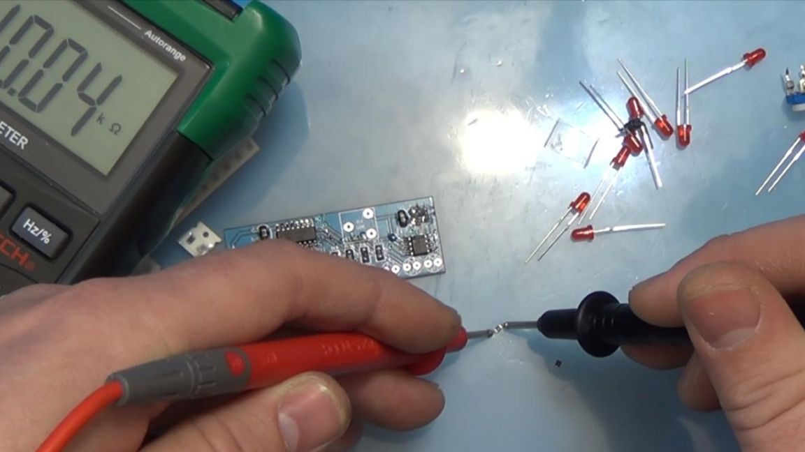
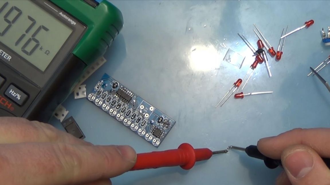
* Multimeter
* Tweezers
* Soldering hair dryer
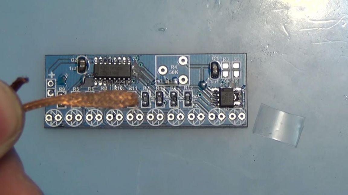
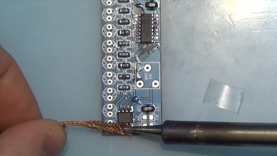
* Braid to remove solder
* Power supply for checking the finished device
That's all it takes to build a kit.
If you don’t have a soldering iron, it’s also possible to solder with a soldering iron, but you will have to tinker a bit, since the chips have enough legs, and be careful when soldering with a soldering iron, do not overheat the microcircuit.
Step one.
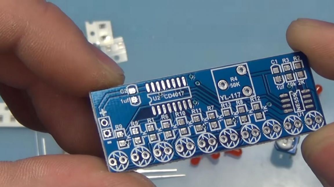
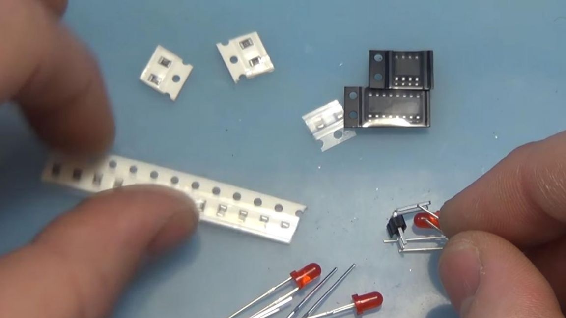
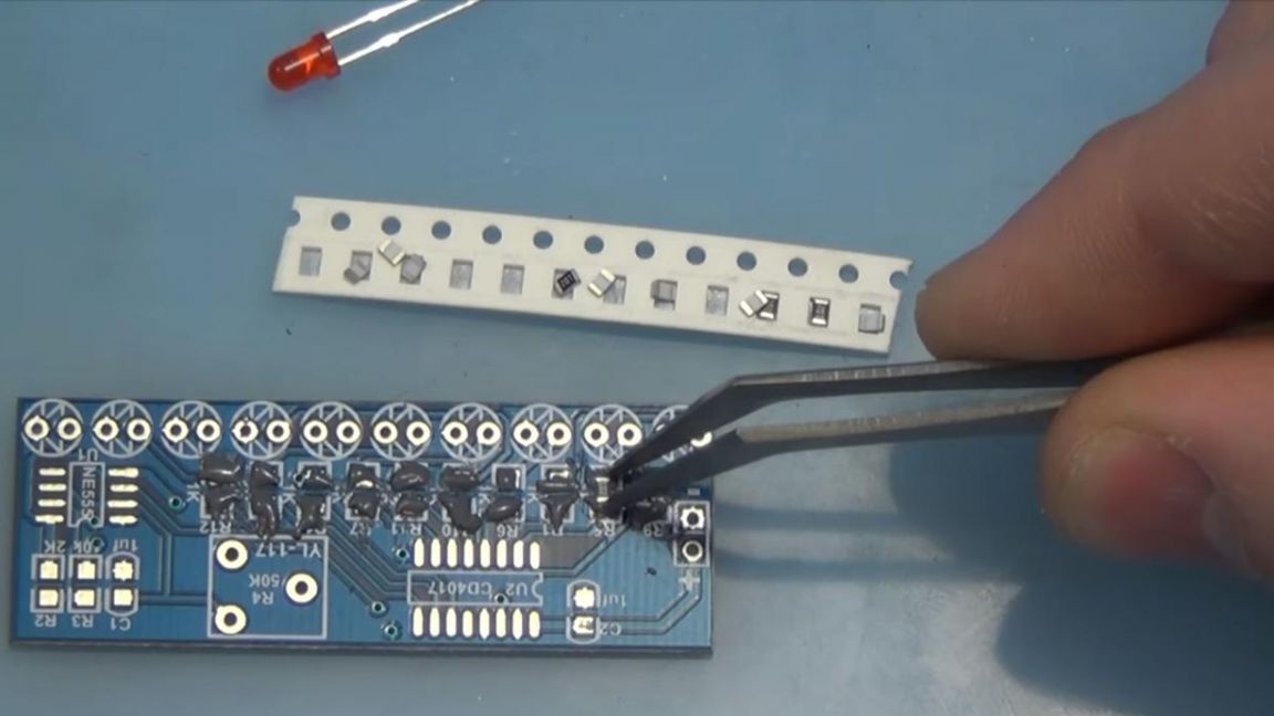
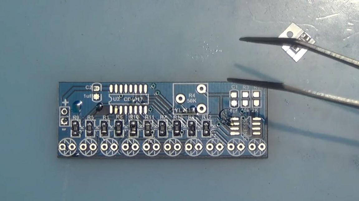
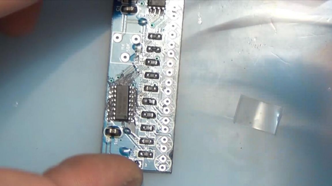
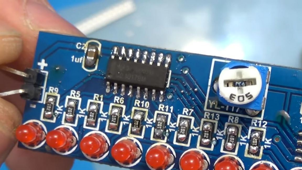
To begin with, it is necessary to place all components on the board, in this case most of them are SMD, that is, they are soldered mainly with a soldering iron, since the board does not have holes for installing components, or in other words, this is called surface mounting technology.
In my case, the soldering will be carried out using a soldering hair dryer and solder paste, which facilitates the soldering process at times, because it does not require soldering, as it already has it in its composition mixed with flux.
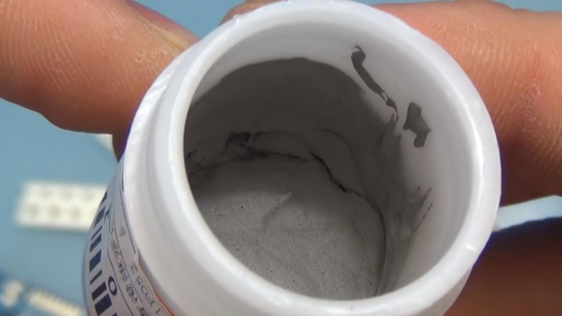
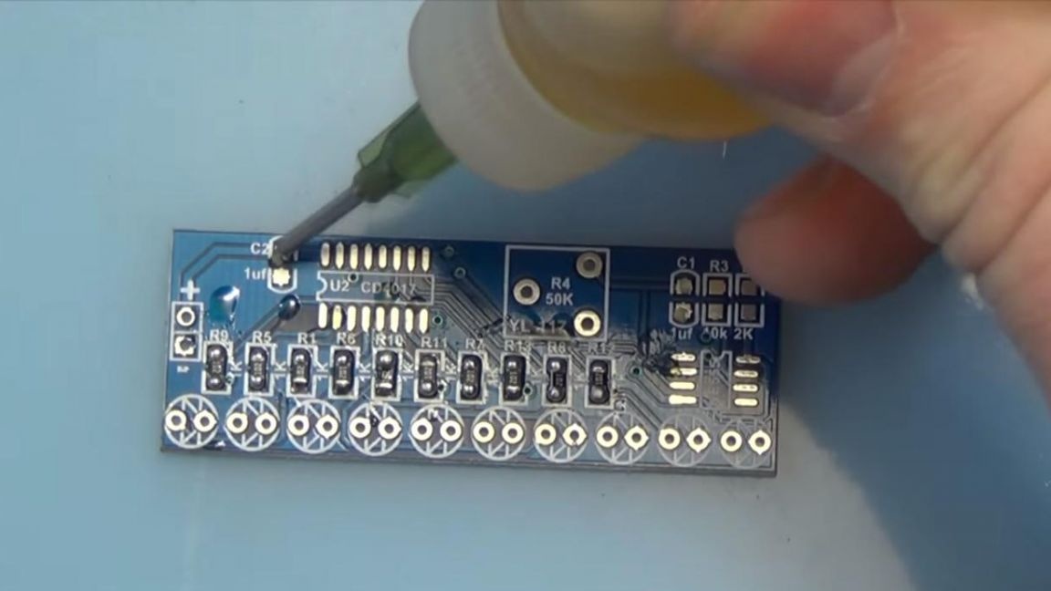
Before placing the SMD components, it is necessary to apply solder paste to the board contacts. It is most convenient to apply the paste with any sharp-pointed part, whether it be a toothpick or tweezers. We apply the paste to each contact separately, the amount of paste should not be too large.
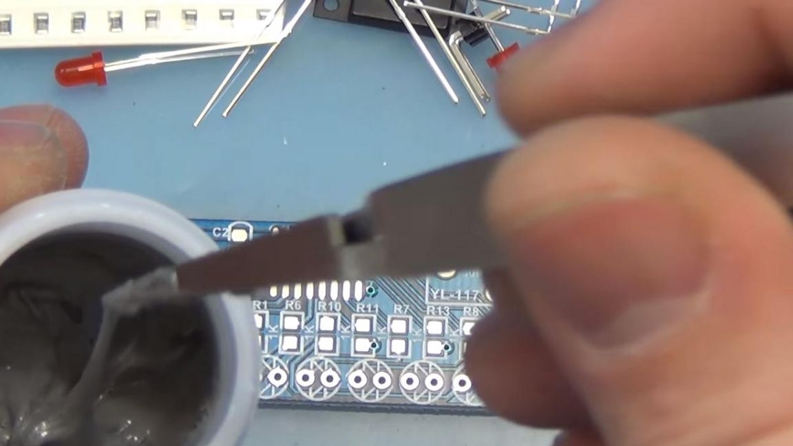
The photo shows that this turned out to be a bit overkill, so I advise you to take smaller portions, twice, or even three.
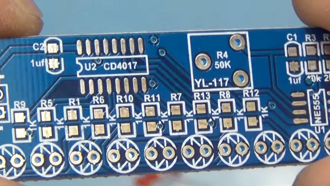
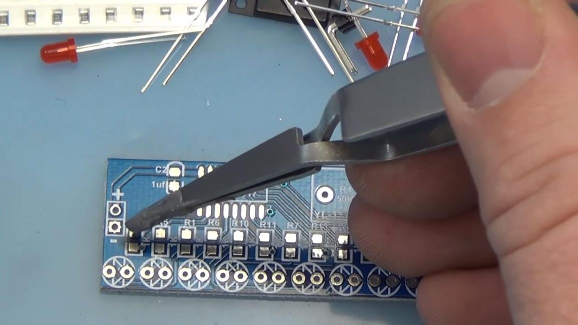
A tuning resistor will be located here, with which you can adjust the speed of the running line.
Step Two
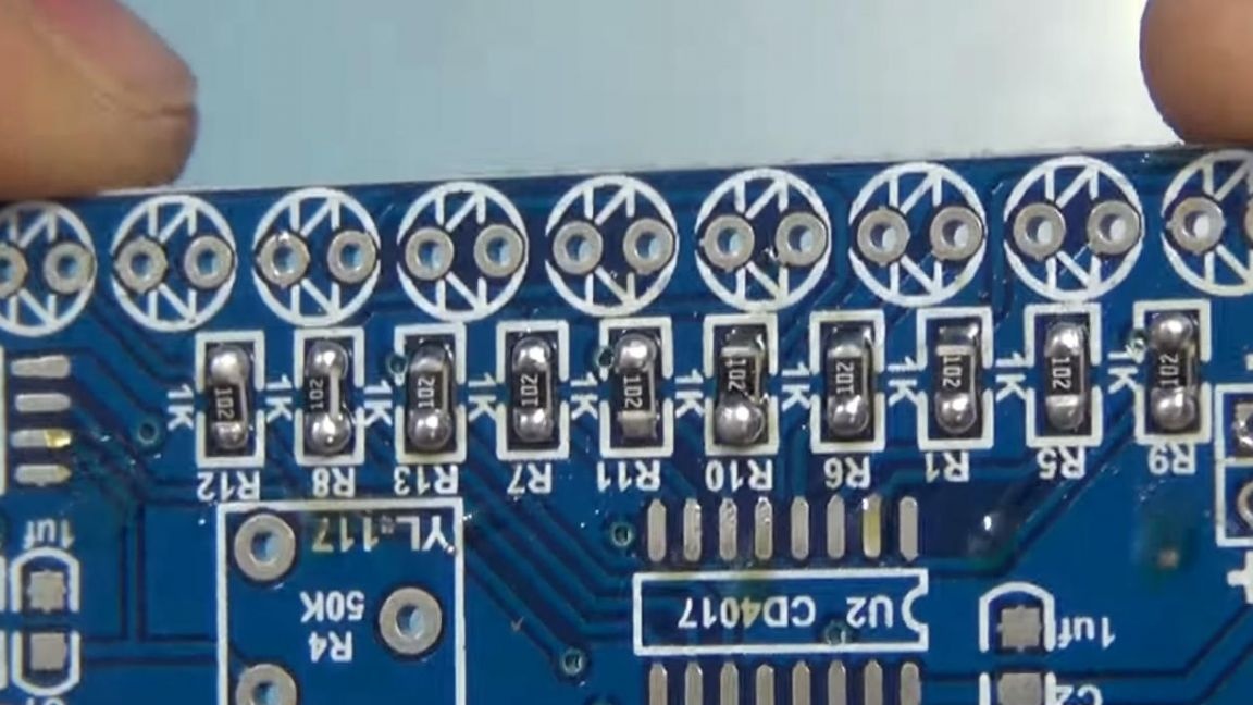
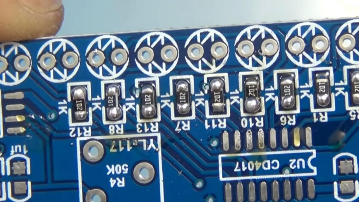
Now on top of the paste we “stick” the resistors with a resistance of 1 kOhm, both on them and on the board there is a designation. Marking 102 on SMD resistors means that the first two digits are a numerical value, and the third digit 2 is a factor, that is, 1kOhm = 10 and 10 times the second power. You can also use a multimeter for fidelity.
Now you can turn on the soldering iron and set a weak wind flow to solder the resistors, if necessary, equalize their position on the board.
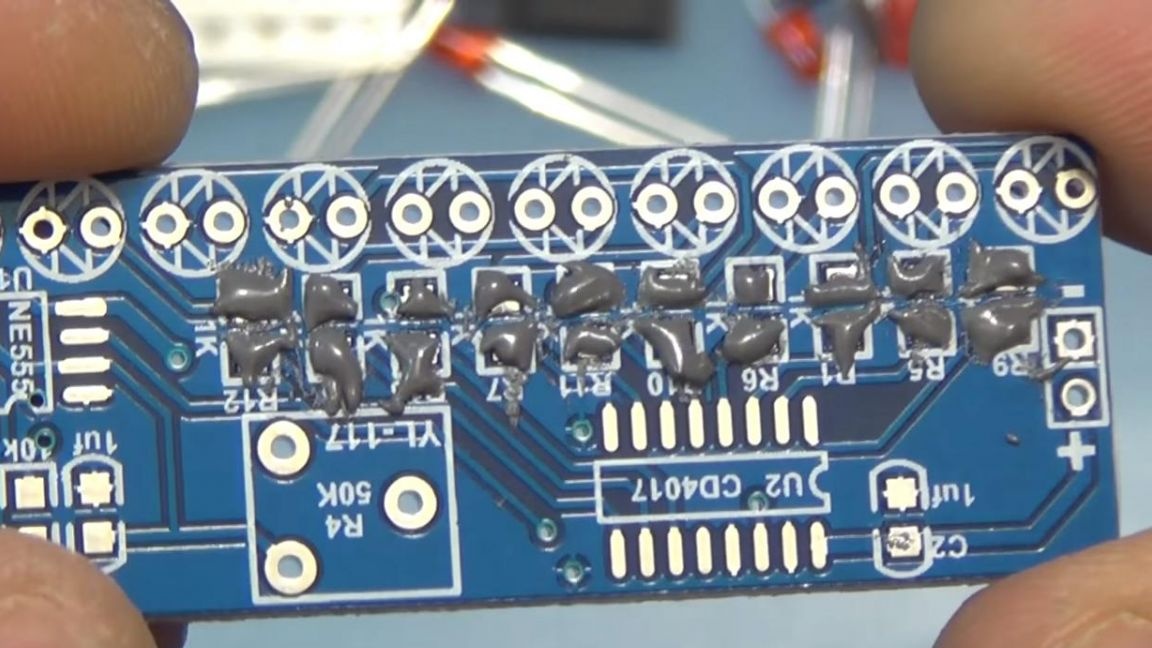
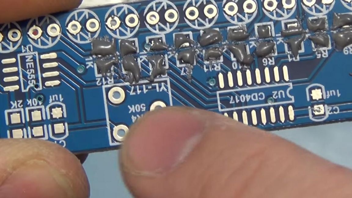
As you can see in the photo, the resistors were soldered well, but in this case there was a lot of solder paste, and in different places.
Therefore, consider these errors and take note, the solder paste must be applied in scanty portions, then the board will look good, as well as the quality of the solder.
Step Three
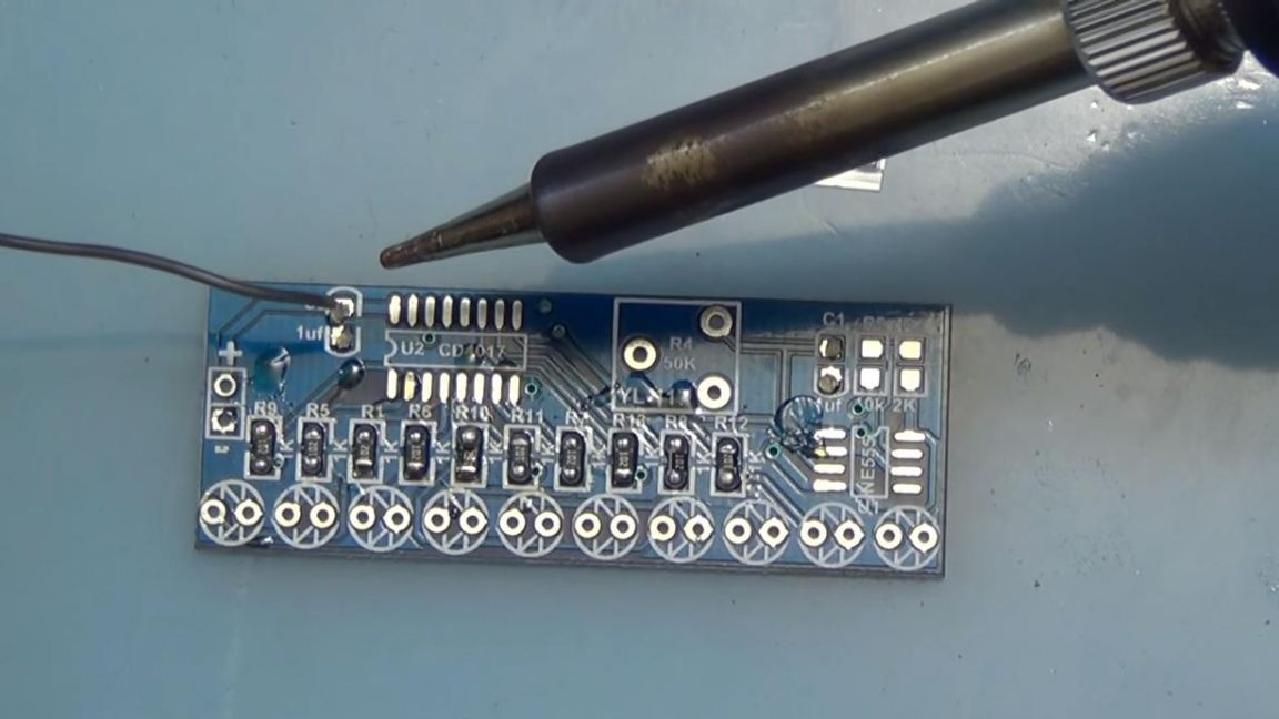
Then we solder the SMD capacitors, we solder them with a soldering iron to show how this is done if you do not have a soldering hair dryer. First, apply flux to the contacts, after which we tin one of the contacts.
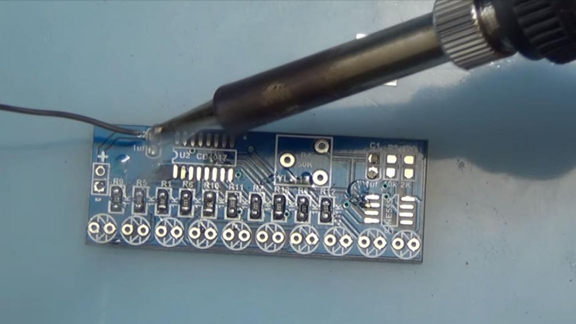
Next, we take the capacitor with tweezers and having set its contact to the place of the previously tinned one, we bring the soldering iron and solder, and now, when one contact already holds the capacitor, calmly solder the second.
It looks like this, which I think is a pretty good result for soldering with a soldering iron, so worrying about the fact that you do not have a soldering hair dryer is not worth it, you can solder this board without it.
Step Four
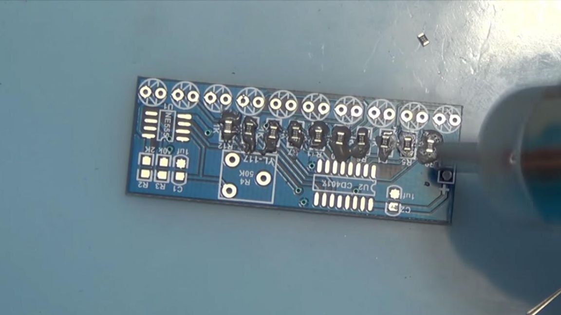
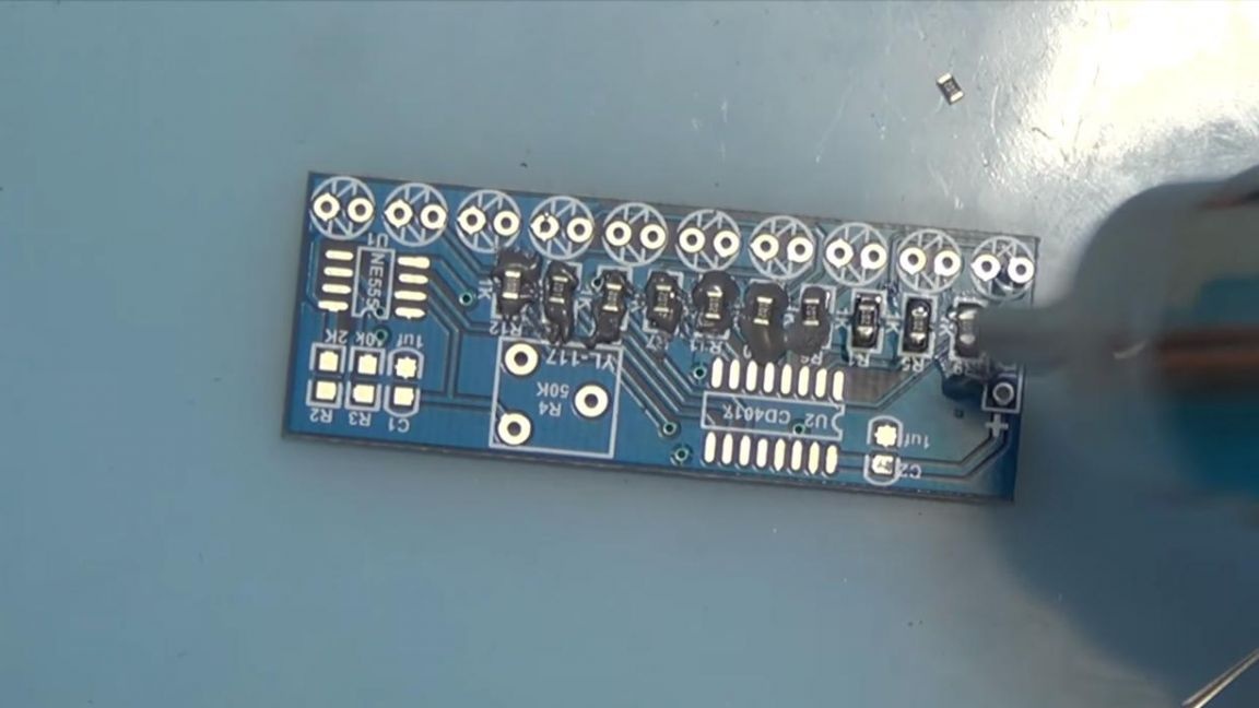
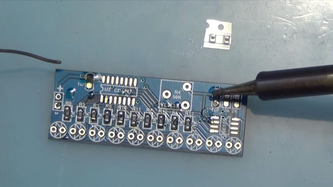
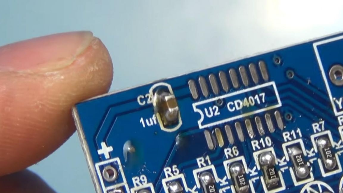
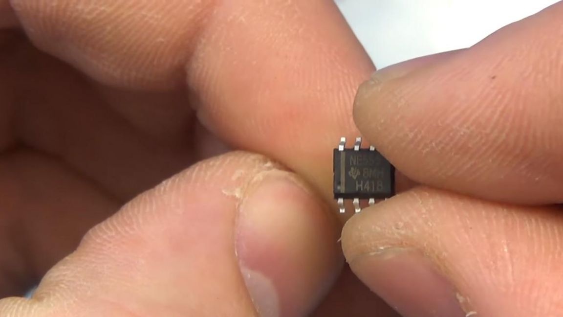
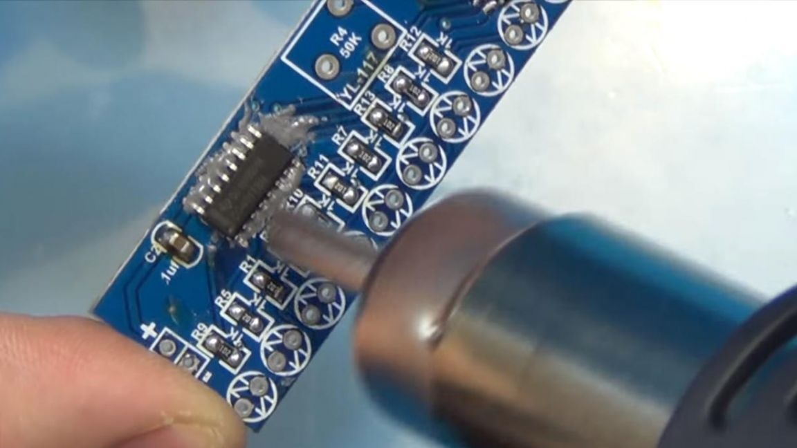
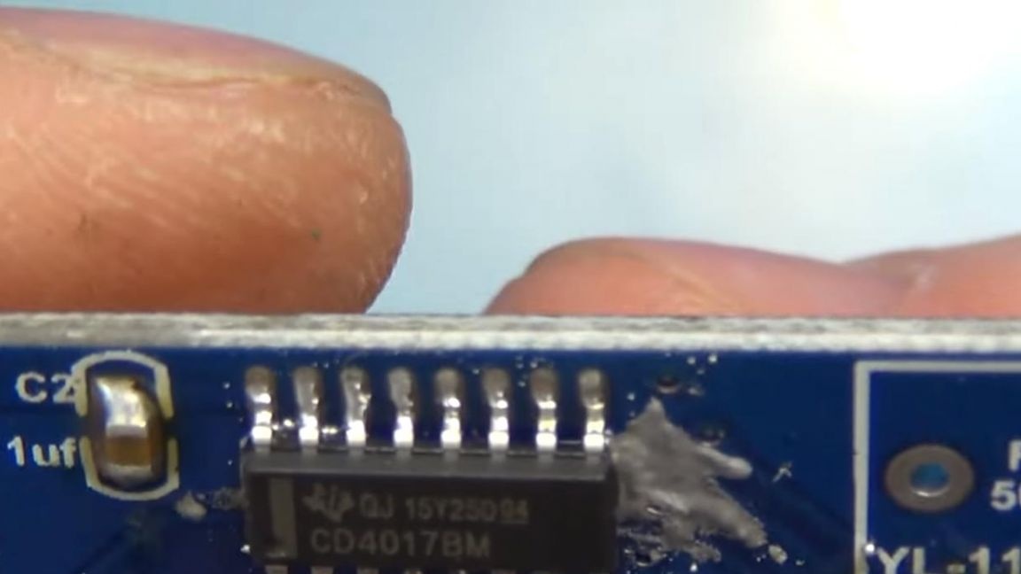
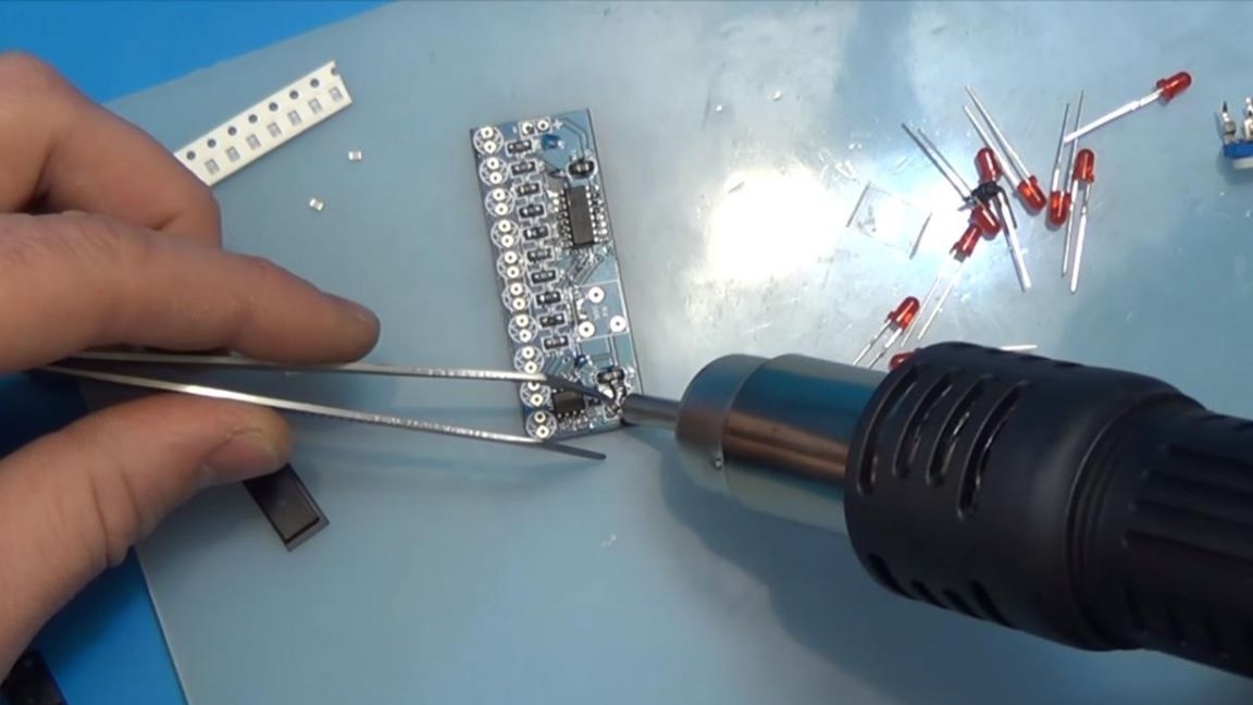
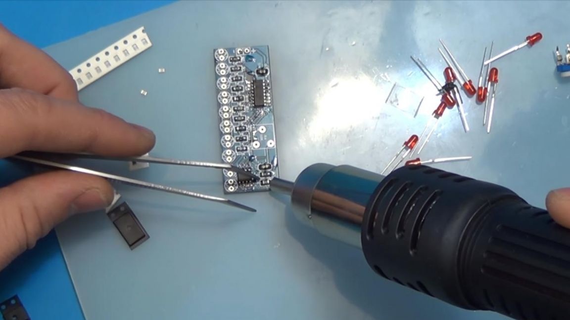
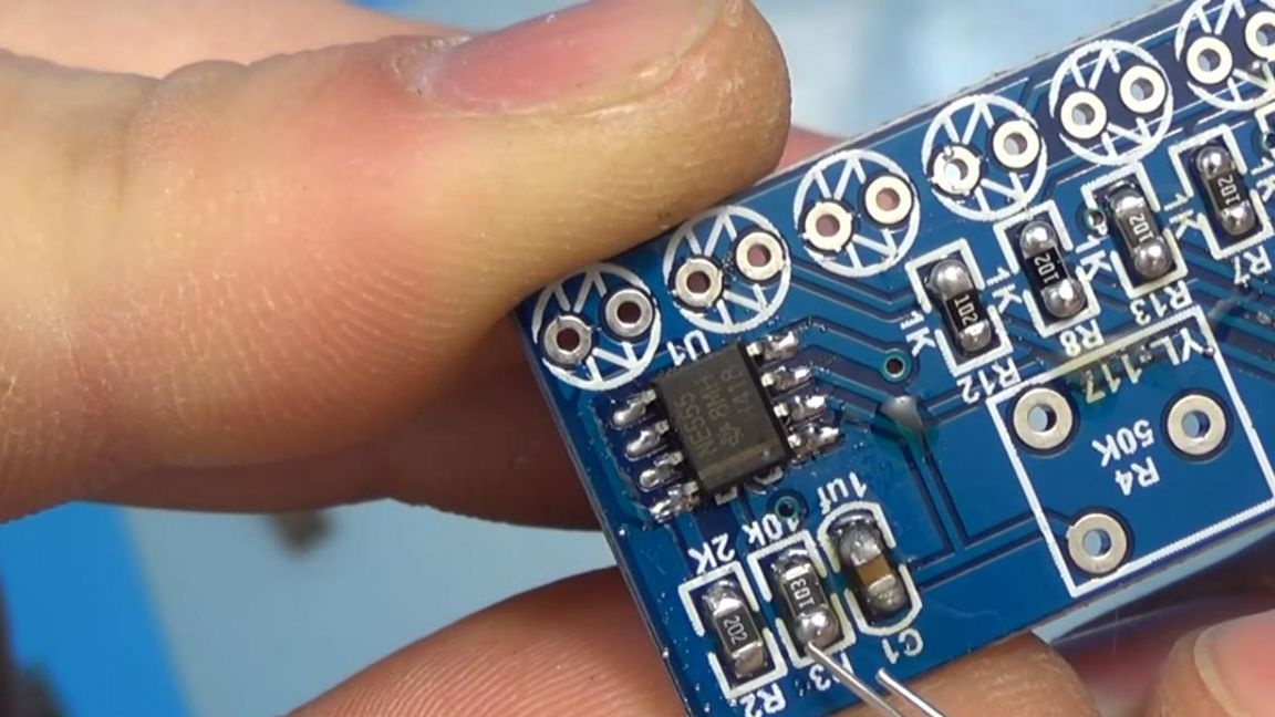
It's time to solder the chips. We apply solder paste to the contacts and install microcircuits on top of them.
For their correct location on the board, you need to combine the strip on the chip with the key applied to the board in the form of a cut off semicircle.
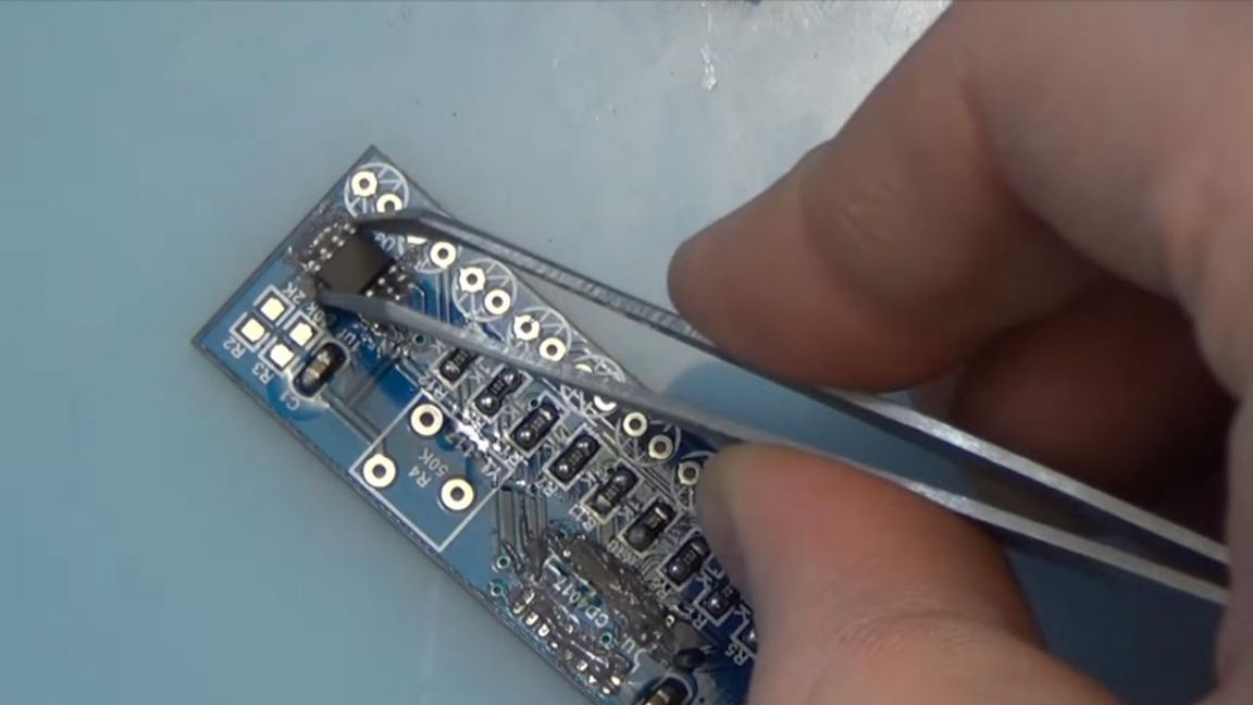
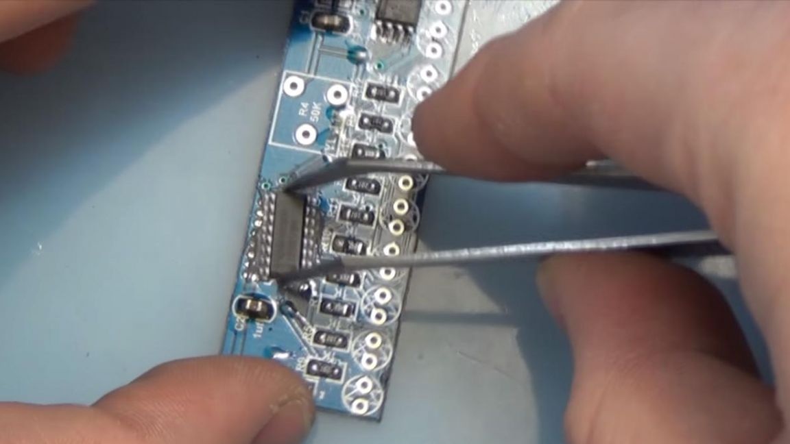
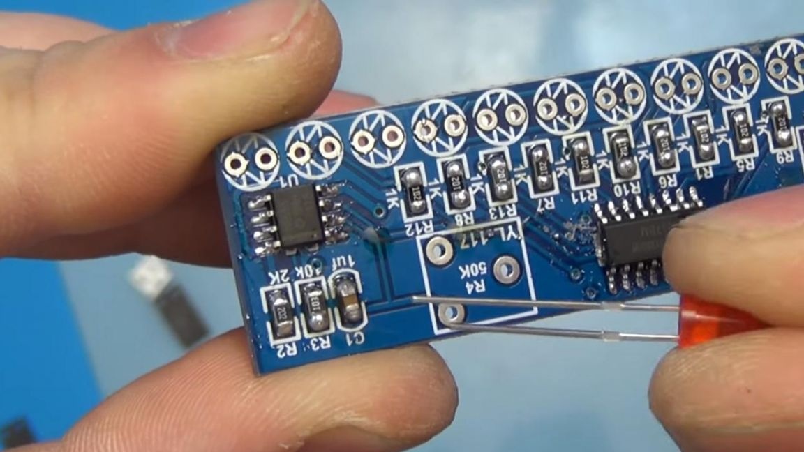
We solder with a soldering hair dryer until the solder is completely melted, we do the same with the second microcircuit, if necessary, tweak it with tweezers.
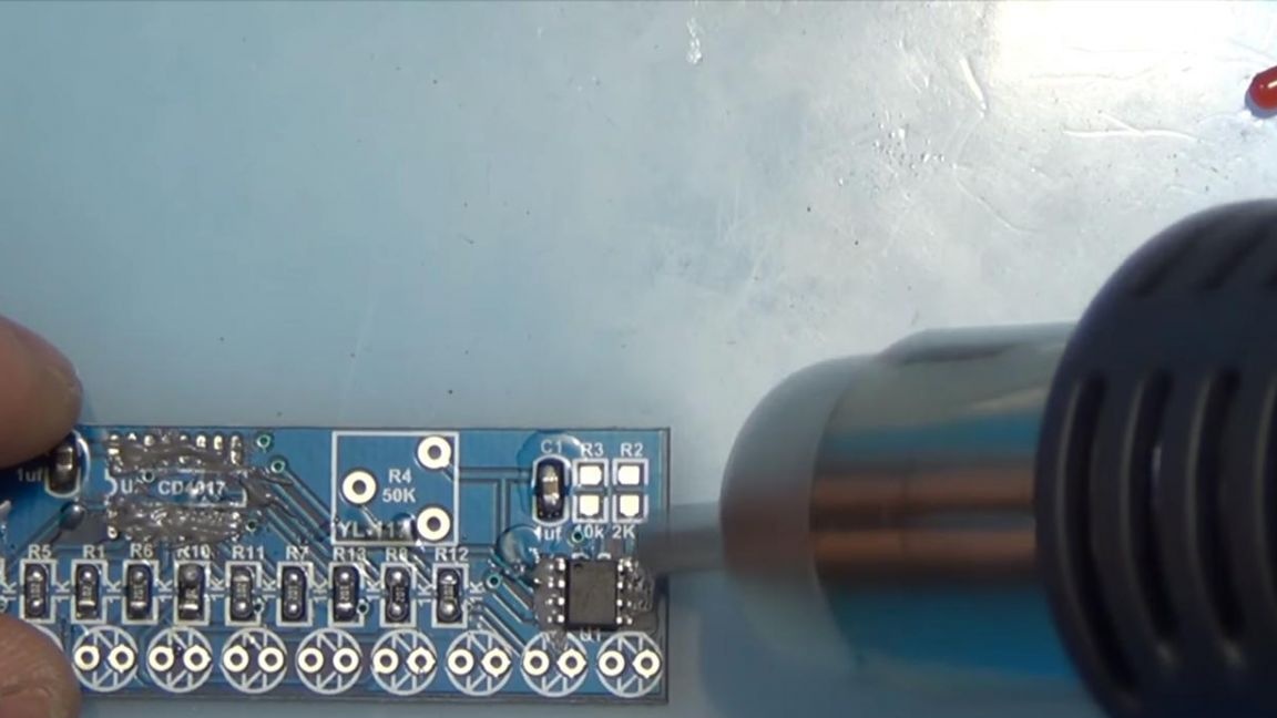
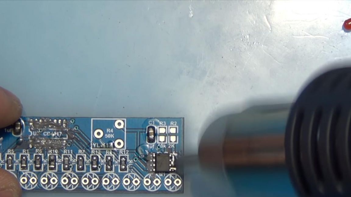
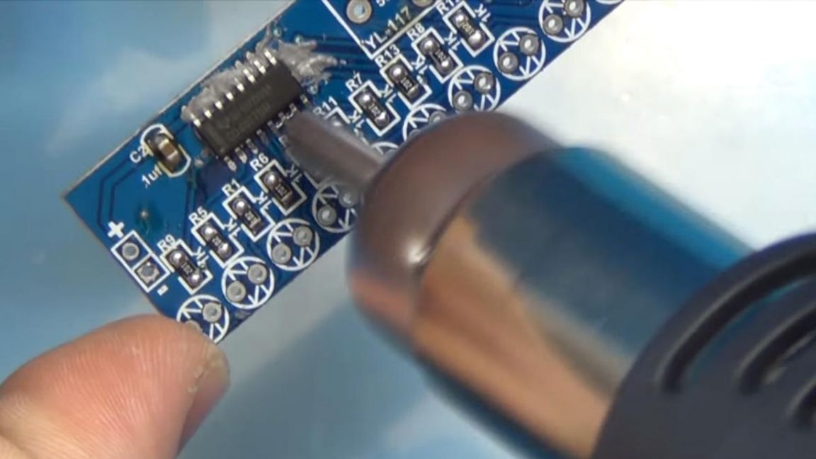
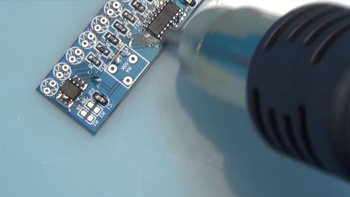
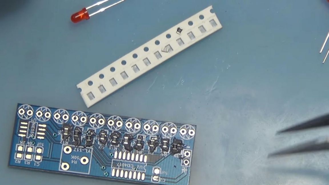
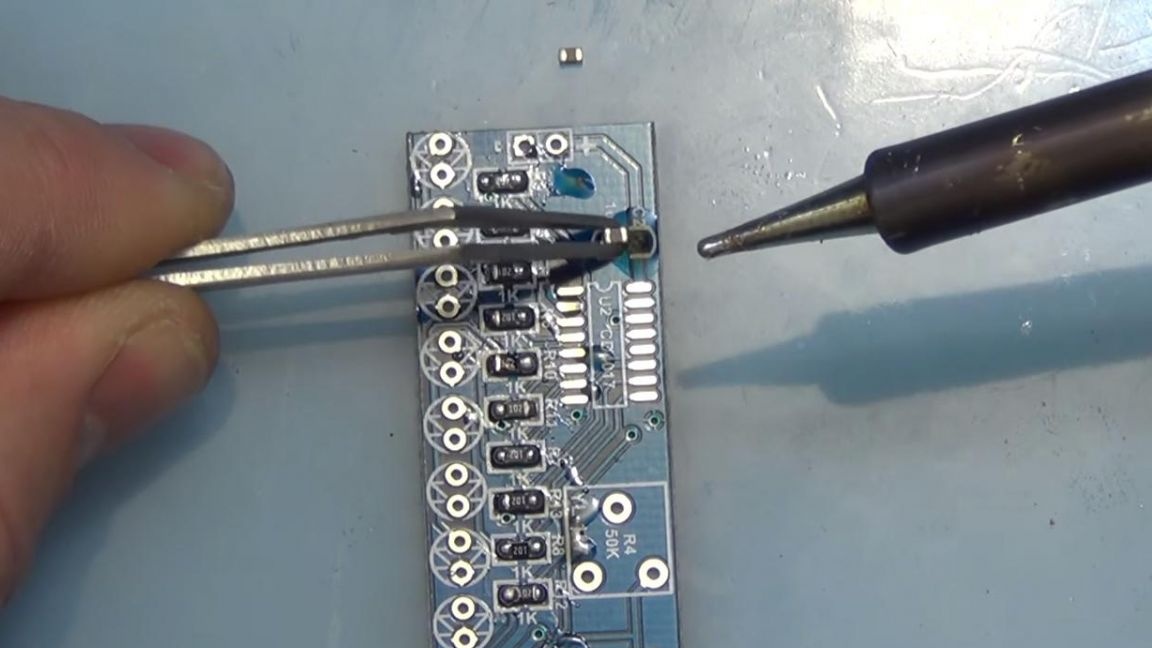
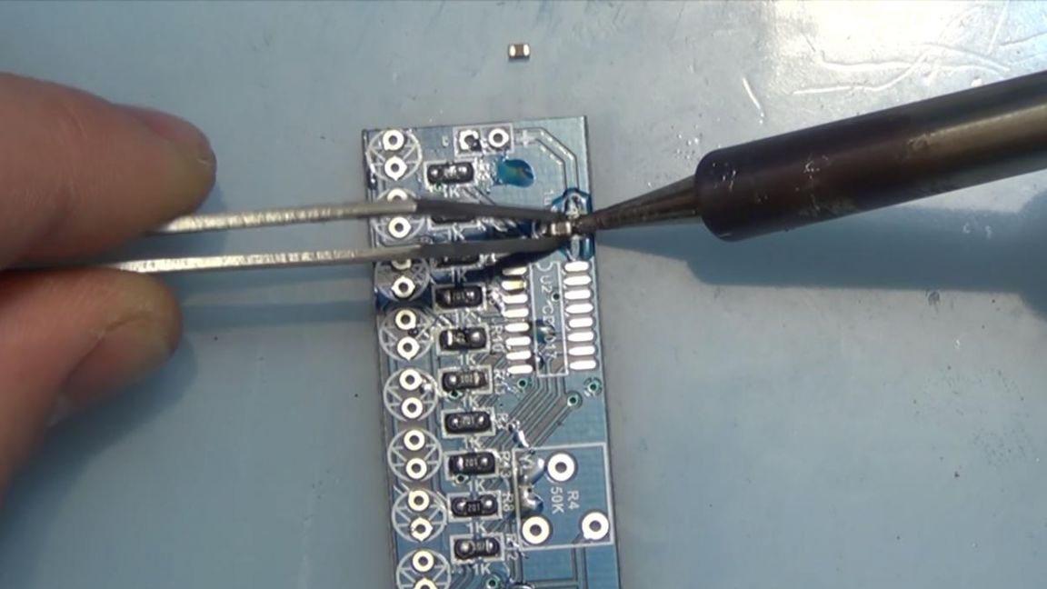
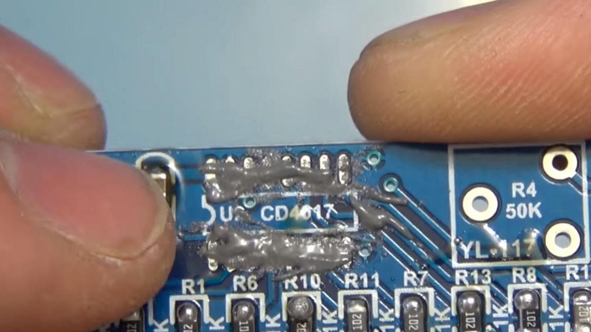
Since there was a little bust with paste this time too, we had to remove the excess with a braid to remove solder.
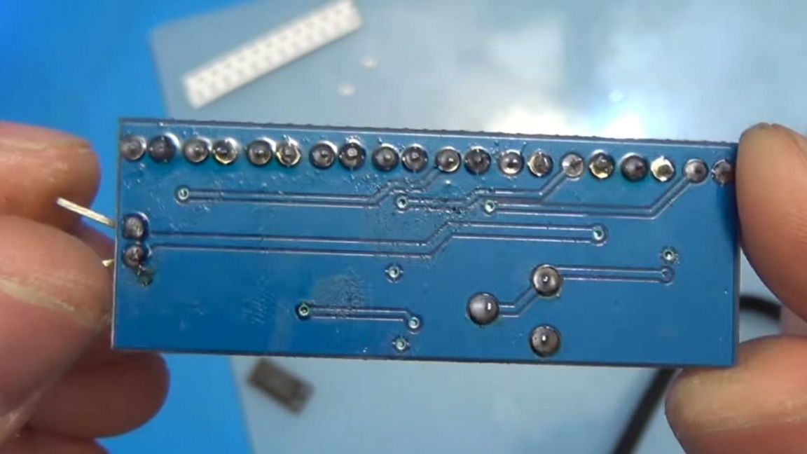
After this procedure, the legs of the microcircuit look like this, there are no junctions between themselves and this is good.
Step Five
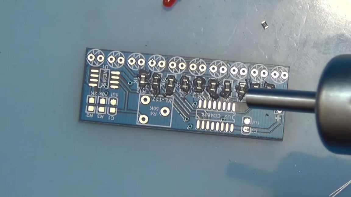
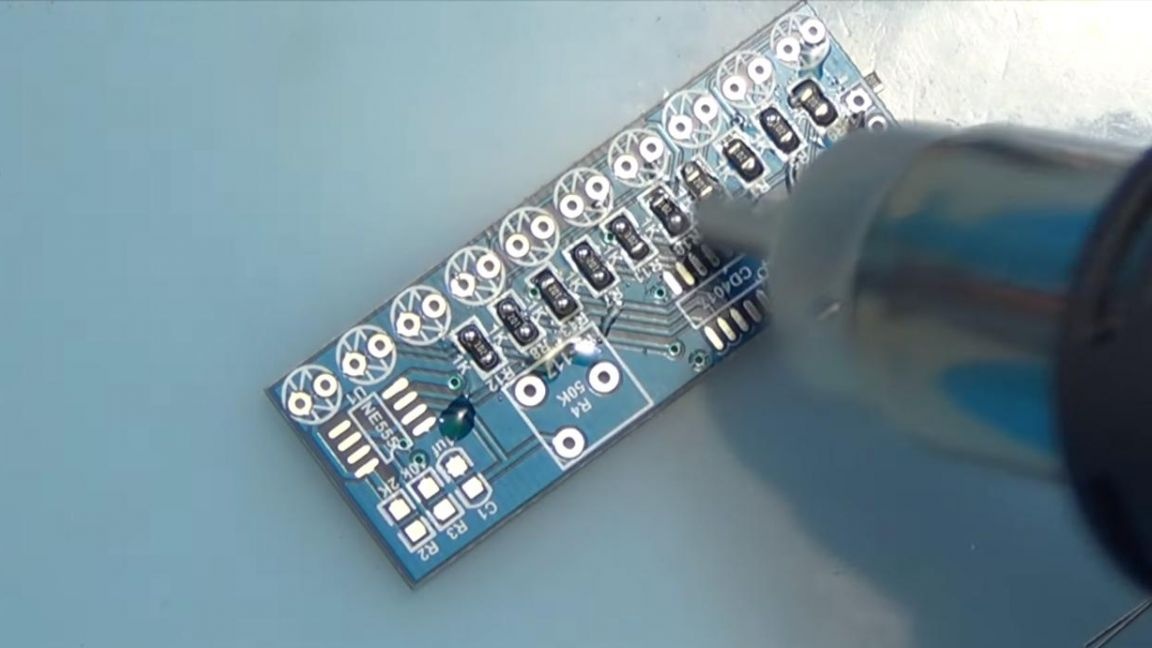
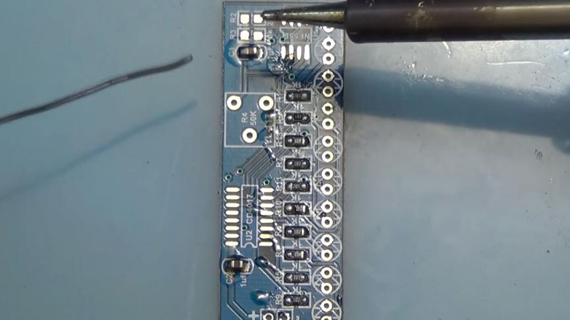
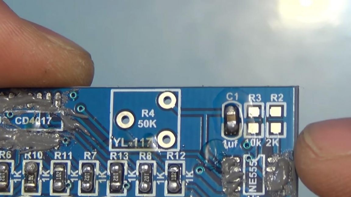
Now we solder the remaining 103 and 202th resistors to their places, as I described their ratings I described earlier.
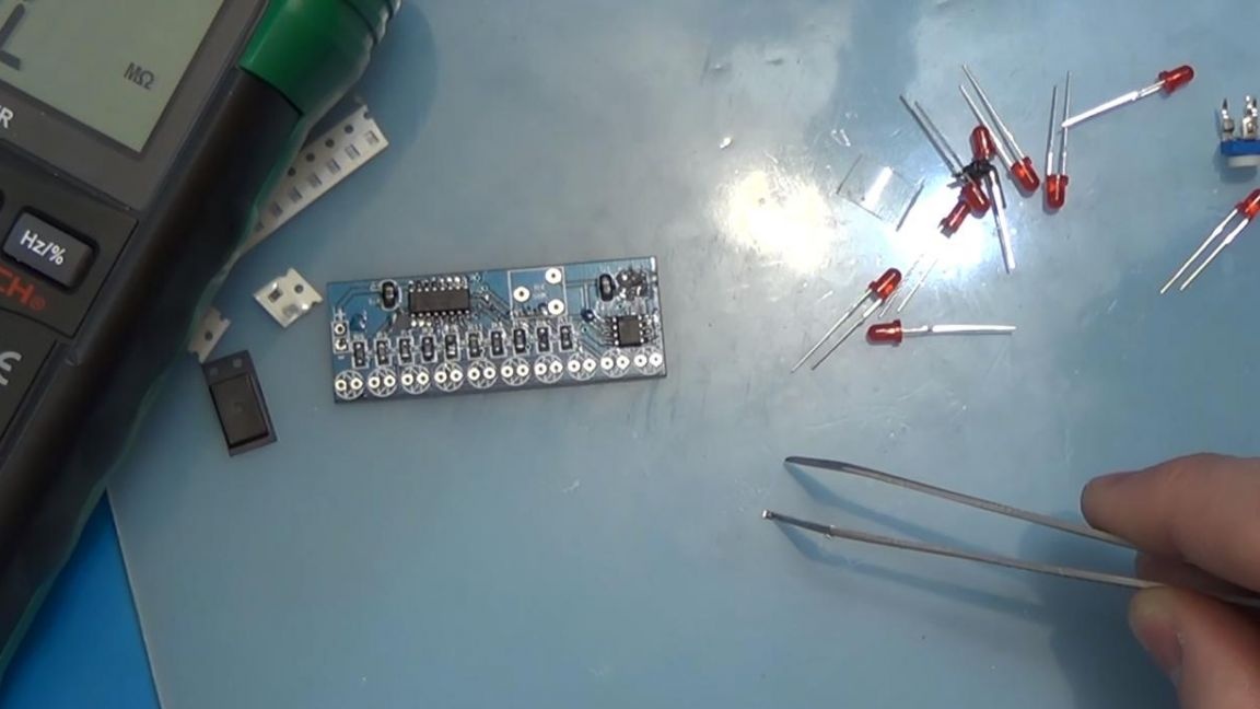
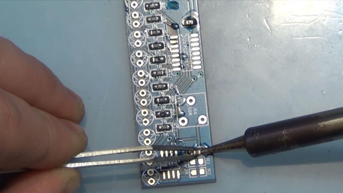
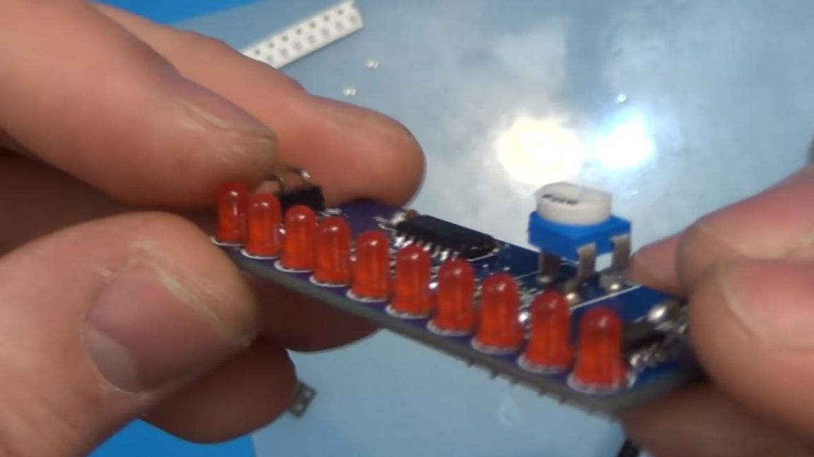
Well, consider it and the board is ready, it remains to solder the tuning resistor at 50 kOhm, this is indicated on its rotating part by the marking 503, as well as on the board itself, as well as the LEDs. After this, we solder the LEDs, the main thing is to observe the polarity, the long leg is plus, the short one is minus. On the board, the minus is shown by the line, and the plus by the triangle. In this case, we solder them with a soldering iron, remove the remains of the conclusions with side cutters.
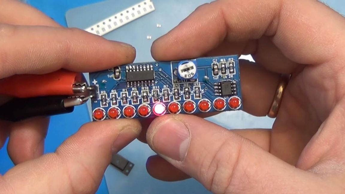
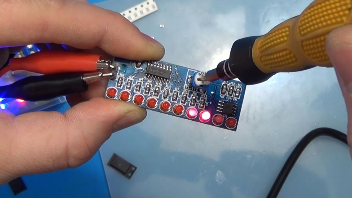
Step Six
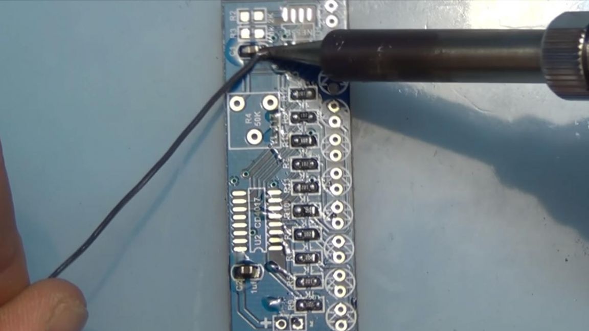
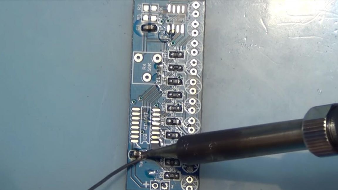
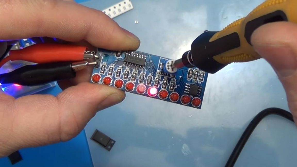
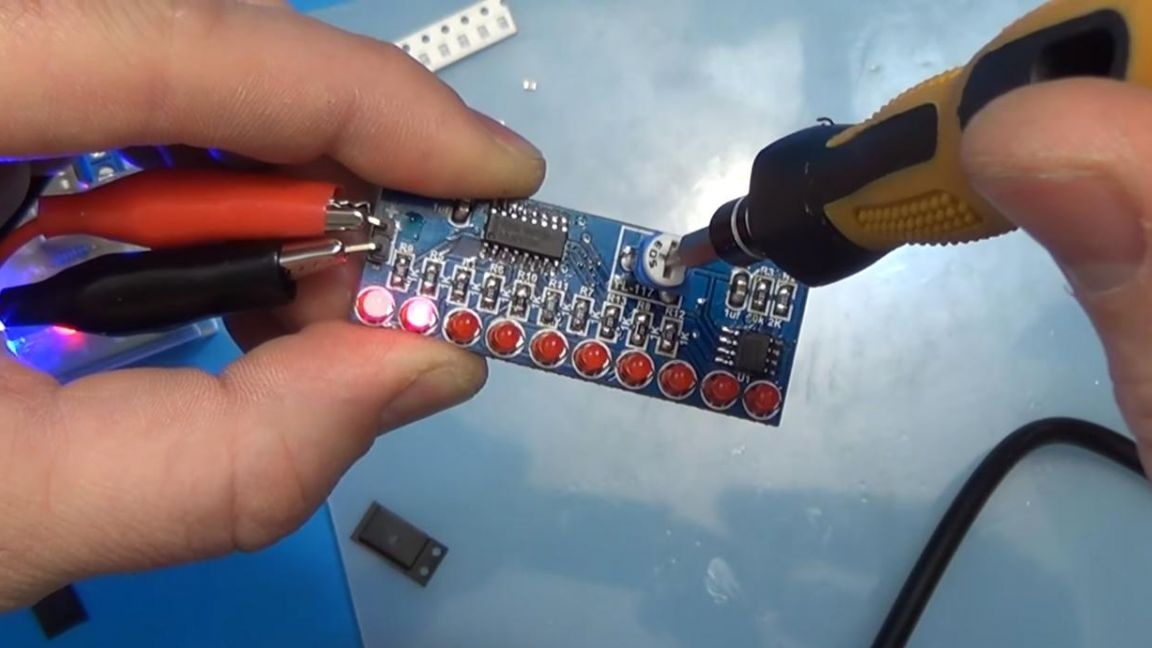
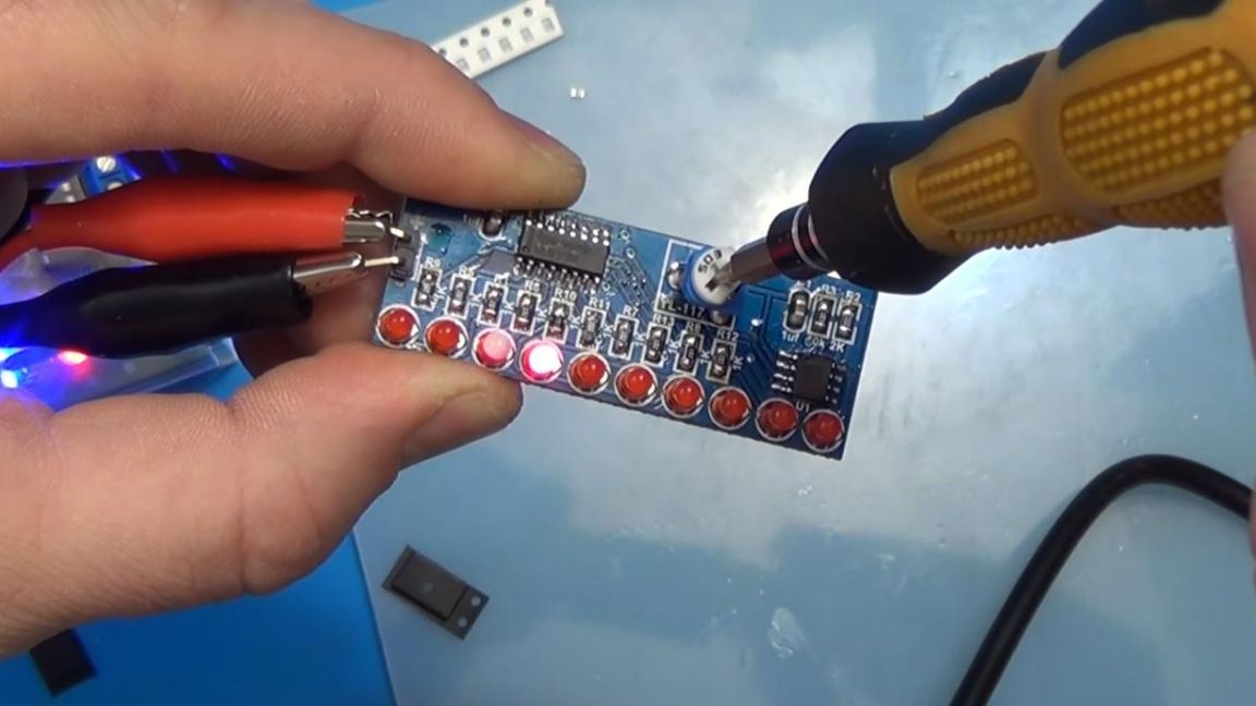
It's time to test the finished device. We connect the power from the unit to the running strip and we see that the LEDs light up alternately, the speed can be adjusted with a trimming resistor, rotating its moving part clockwise to increase or counter- to decrease.
That's all for me, thank you all for your attention and successful assembly of the kit-kits.