When living outside the city, sometimes you find yourself in a situation where the house is disconnected for external reasons, the electricity is turned off. It is especially unpleasant when, at this time, a thunderstorm, bad weather or twilight has already set in. There is not enough battery for a long time, and sitting in the dark is joyless.
To overcome this situation, it is proposed to manufacture a portable battery lamp that functions as a flashlight, a table lamp, or a standby source of indoor lighting.
As a power source for the flashlight, we use a replaceable battery from a screwdriver, which has a significant capacity. This tool works periodically, and batteries are even less common. We use it for lighting, and when the electricity is connected, we charge it.
Making a battery lamp.
1. We select a light source.
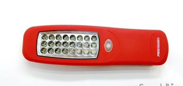
An inexpensive LED flashlight with a matrix of 24 LEDs was purchased as a light source. The lenses of all the LEDs are cast in one block and give a concentrated beam of light, which has good brightness. The flashlight is powered by three batteries and consumes a current of about 150 mA.
2. The source data:
We have:
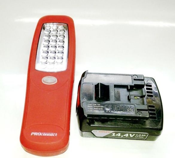
- a battery from a screwdriver (power supply - 14.4 V) and an LED flashlight (light source - 4.5 V).
It is required:
- assemble them into a single (collapsible) design;
- electrically coordinate their nutrition.
3. Making a mounting device for the flashlight.
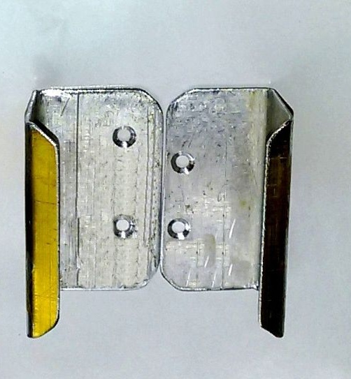
From an aluminum square 30 x 30 mm, we cut two parts 50 mm long.
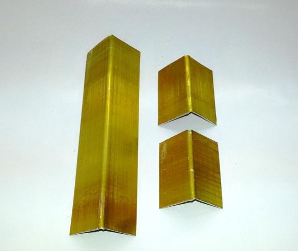
We perform mechanical processing of the ends (alignment, removal of sharp edges, radii and chamfers), bend the holding shelves, at a distance depending on the thickness of the flashlight body (in our case, 24 mm). As a result, we get the right and left halves of the capture.
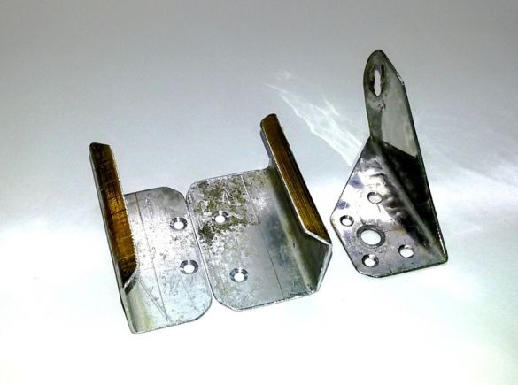
To complete the mounting device, from a stainless steel sheet with a thickness of 1.0 ... 1.5 mm, we cut out and bend a transition angle to 90 degrees, which allows us to direct the light beam from the “down” position to the “up” position due to rotation.
We drill connecting holes in all the details, and on the inside of the grippers we apply deep chamfers to install the fastener heads flush with the plane. We assemble (with screws or rivets) a mounting device for a flashlight.
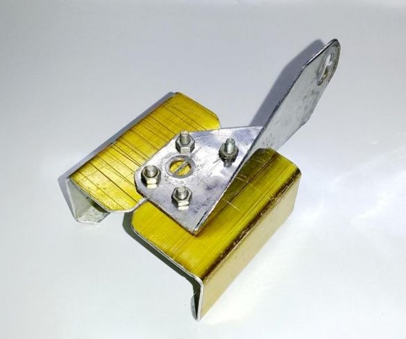
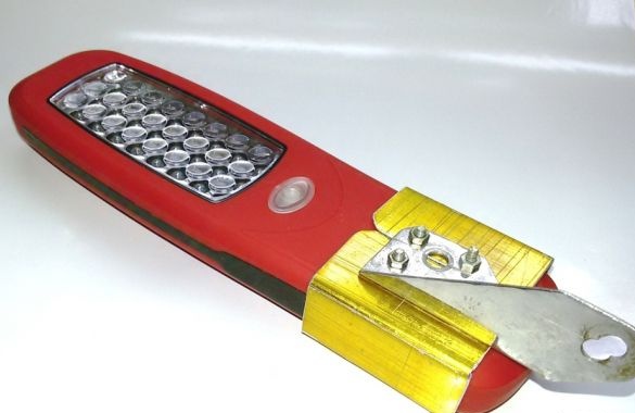
Check the installation of the flashlight in the device. If necessary, by editing or filing, we bring the details of the device to a tight entry of the flashlight.
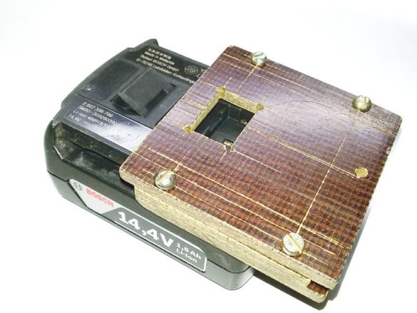
4. Making the base - current collector for the battery.
From the PCB sheet 5 mm thick, we cut out the base details.
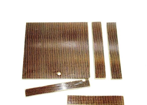
Dimensions of parts are selected in accordance with the dimensions of the battery.
The thickness of the parts 5 mm is determined by the size of the guide groove in the battery and at the same time gives sufficient strength and rigidity for the manufacture of the structure.
The basic structural detail is a 75 x 70 mm rectangle. This is followed by two guides 12 x 70 mm and two intermediate gaskets 8 x 70 mm.
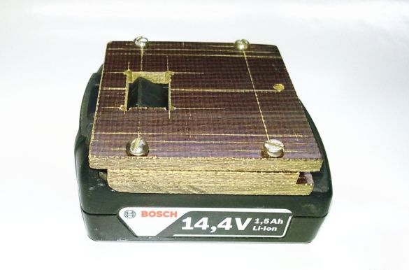
We assemble (with screws or rivets) the details of the base for the battery. After assembly, we adjust the dimensions of the structure with a sawing for smooth sliding of the base along the grooves of the battery.
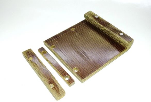
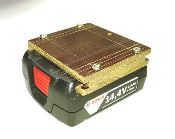
We adjust the length of the base guides (from the front) to the possibility of installing it flush with the front of the battery. In this position, we mark out a rectangular window for the spring lock of the battery to enter, when the base is installed on it in the working position. We remove the base and process the window - we drill holes at the corners of the window, drill a rectangle making holes inside the marking outline, mechanically process the window along the marking lines.
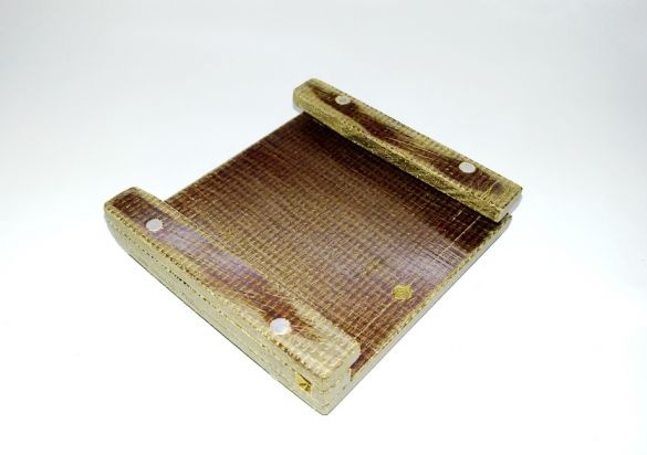
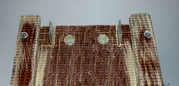
In the working position, in the back of the base, we note the location of the grooves with the battery contacts. According to the marking, we cut two grooves in the base plate, under the positive and negative current collector contacts. We manufacture two L-shaped electrical contacts and install them in the grooves, fasten them with the screws while drowning the heads.
5. To agree on the power of the flashlight and battery, consider the device of the flashlight.
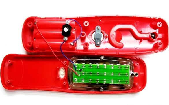
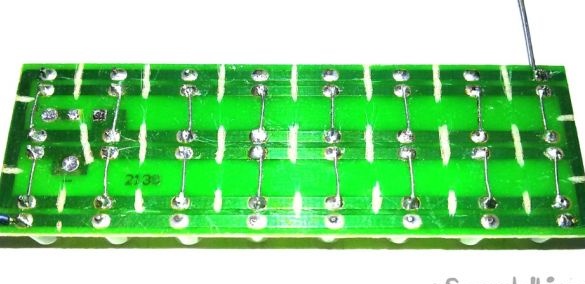
An open flashlight brought some disappointment. All 24 matrix LEDs are connected in parallel and connected to power through a single 2.2 ohm resistance.
And this means that when one (the weakest) LED is burned, the current to the others when switched on in parallel increases automatically, which increases the chances of burning the next LED, etc.
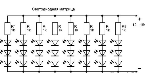
This situation needs to be fixed. In order not to set a separate resistance for each LED, we use a mixed connection. Such a connection method is the most optimal. It involves a combination of parallel and serial connection. The circuit provides the inclusion in parallel not of individual LEDs, but of sequential chains of them. Each circuit has a current limiting resistance. As a result of this, even if one or several chains fail, the LED matrix will continue to shine without threatening the rest of the LEDs.
Since the LEDs do not have any marking, then to determine their characteristics we solder one LED and check it on the multimeter.
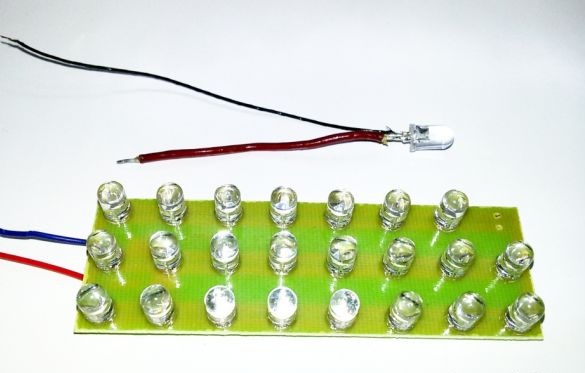
We turn on the LED through the chain - a limiting resistance of 510 ohms, a variable resistance of 1 kom ... 4.7 kom, a 12 V power supply and changing the resistance, we determine the current consumption of the LED by the device according to the maximum brightness of the glow. We dwell on the readings of the device 8 ... 10 ma.
Measurement of the voltage drop on the LED showed a value of 2.8 V. With a minimum voltage of 12 volts on the used battery, we calculate (12 / 2.8 = 4.3) and determine that no more than 4 LEDs can be installed in a series circuit. But taking into account the voltage drop across the limiting resistance and the driver's control elements, we select a sequential chain of 3 LEDs. In addition, the arrangement of elements on the board contributes to this choice.
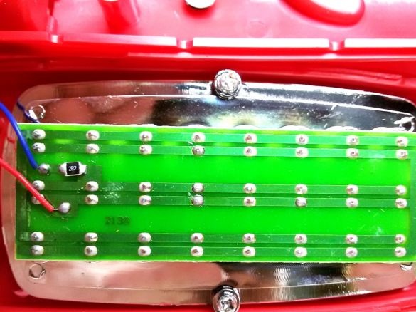
We release the board from all external connections, solder the control LED into place and form a new LED switching circuit.
To do this, remove additional resistance from the board and cut the connection paths for turning on the LEDs, except for one from the edge of the board connecting the cathodes of the LEDs.
Before the change, along the board there were three rows of 8 parallel-connected and equally spaced LEDs. Having cut the longitudinal tracks, we connect the adjacent LEDs in the transverse direction with jumpers. We get 8 rows of 3 LEDs connected in series.
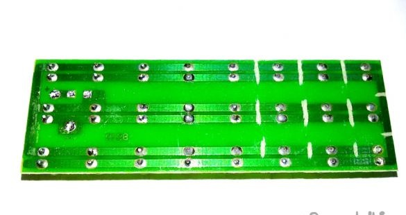
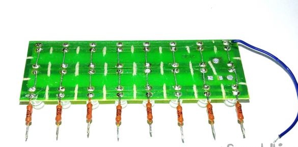
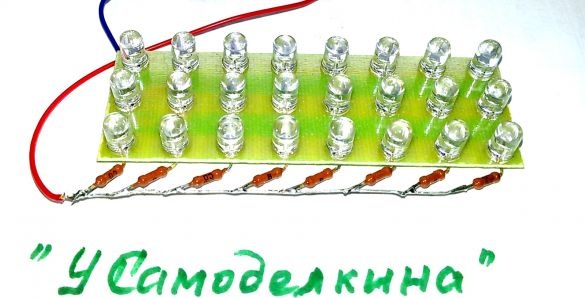
From the anode side of the LED chain, in each row, solder the limiting resistance of 1 com. By connecting the free ends of the resistances, we obtain a positive conclusion of the matrix. The negative output is connected to the untouched track on the board.
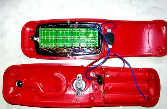
We install the assembled LED matrix in its old place in the flashlight, connect it through the standard switch to the battery compartment. This option of switching on a new matrix can be used when using one flashlight with standard batteries, but for this it is necessary to add a boosting DC-DC voltage converter from 3 to 10 ... 12 V. to the flashlight (between the batteries and the LED matrix). on sale, for example on. However, even easier, in the evening you can make from home friable similar electronic device on one or two transistors. Schemes and descriptions are offered on our website.
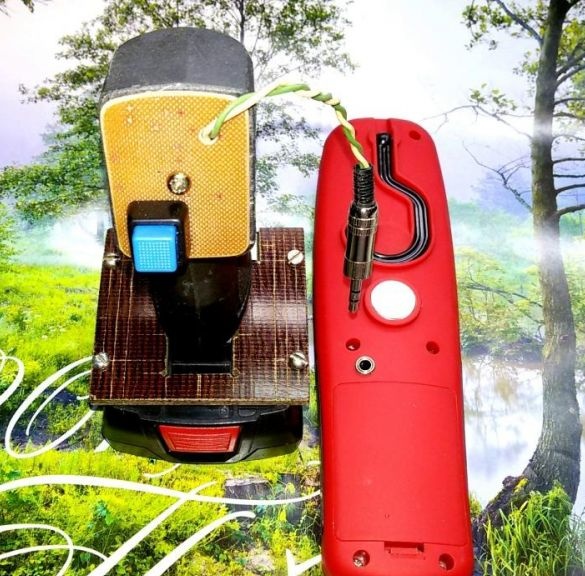
To connect the flashlight to the battery, we introduce an additional connector. On the back wall of the flashlight housing, install a three-stage socket for the Jack 3.5 connector and connect it to the LED matrix through the switch spring contact of the socket. Then the external power will be connected to the flashlight when the “Jack 3.5” plug is connected to the battery, automatically turning off the regular power and vice versa.
Due to the fact that the current-limiting resistances are calculated according to the maximum possible voltage on the battery (17 volts), installed and adjusted according to the current on each LED circuit, and the voltage on the battery will only decrease (up to 12 volts), we can assume that the minimum finalization of the flashlight is completed. Although improvements to the design are possible. This is the introduction of the driver for LEDs, indicating or turning off the battery at low voltage.
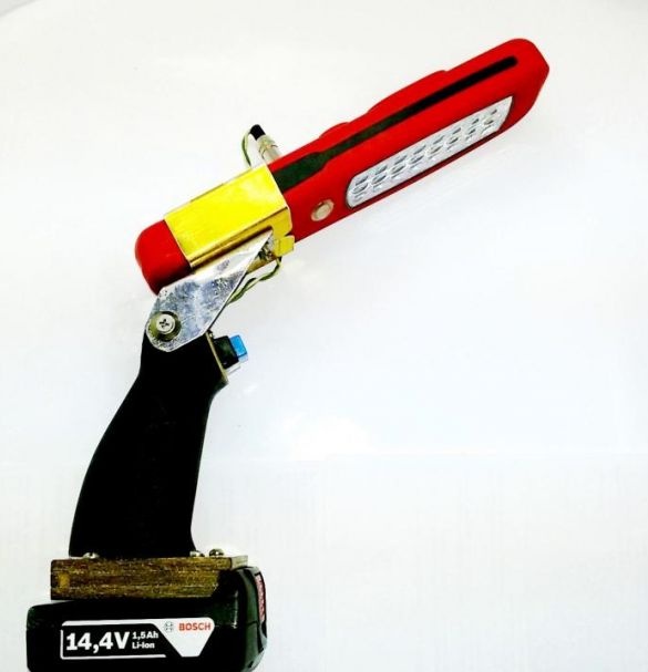
6. Assembly of the design of the battery lamp.
To connect the base - the current collector with a flashlight, we use a transition piece in the form of a handle convenient for using a flashlight. The handle can be made of thick-walled plastic pipe, cut out from a piece of plastic or fashionably made on a 3D printer. Install a switch in the handle, remove the power plug and wires for connecting to the current collector.
Putting it all together we get what we want.