

Even with the “preliminary design” - at the idea level, it was decided to move the power sources into a separate building. Generally speaking, there is a fair amount of sense in such a “volt,” especially for a subject subject to all kinds of interference and background, a vinyl corrector — removing a source of powerful electromagnetic fields — transformers — for some distance. On the other hand, the power supply in a single-stage cascade is located in the signal circuit and it is desirable to minimize all connections, in a word - a compromise, as always, as elsewhere. The advantages of the solution can also be attributed to a significantly simpler design of amplifiers and their layout. The smaller weight of each unit - the amplifier, despite its modest power, turned out to be very difficult, with a power supply unit, it would be difficult to move it alone.
The power supplies of modern tube amplifiers often use a half-wave circuit with a mid-point of the transformer winding, kenotron rectifiers and filters with chokes. In addition to the retro look, such a construction scheme is justified by several advantages, which, nevertheless, are more economical and easier to implement them on a modern elemental base. Advantages include some peculiarities characteristic of vacuum devices due to which no interference occurs in the rectifier when switching diodes in the rectifier bridge. When using the classical diode bridge, such interference can be eliminated by shunting each diode with a small capacitor of about 100 nF, to the corresponding voltage and using “fast” diodes.
Automatic delay of anode voltage supply - as the cenotron cathode warms up. The fact is that the resource of receiving-amplifying lamps increases significantly when the anode voltage is applied, when the cathode of the lamp is already warmed up. This usually takes several tens of seconds. Here, it is proposed, having sacrificed the resource of the kenotron, to extend the life of amplification lamps, however, nowadays kenotrons also have a fair value, in addition, delaying the supply of high voltage is quite simple to arrange with a simple timer circuit with an actuating element in the form of an electromagnetic relay, on a modern element base.
Here, it’s worth saying that for the cascade to operate on a vacuum triode, three voltages are required - a negative bias voltage (sometimes, with "automatic" bias, it is obtained by a voltage drop on a special resistor), the voltage of the cathode heating thread or the "directly heated" cathode itself is voltage " glow ”and finally -“ anode ”voltage. When applying voltage stabilization in the power supply, it is unacceptable to stabilize one or only a few voltages. It requires stabilization of all, otherwise, when the mains voltage changes, the radio tube mode may go beyond acceptable limits.
The described power supply, built on semiconductors, contains in one case two independent power supplies - for tube power amplifier and the same vinyl corrector. Each of them consists of a relatively high-current voltage source for supplying lamp filaments and low-current, but high-voltage for the “anode” voltage. All sources are stabilized, anode voltage supply is delayed manually by switching toggle switches. In the power supply, it is possible to use the "standby" mode - the supply of a reduced filament voltage and anode. This mode allows you to not completely turn off the amplifiers during long interruptions in listening, saving the life of radio tubes and electricity - like any devices with a filament or an incandescent coil, when a filament voltage is applied, a current surge occurs due to the low resistance of the cold spiral, it significantly reduces the resource appliances - most often, they fail at this moment. However, it is impossible to completely remove the anode voltage for a relatively long time, leaving only the cathode warmed up - in the latter irreversible changes occur, called “cathode poisoning”. Block switching algorithm, reverse - anode voltages are removed, after five to ten seconds you can turn off the filament voltage.
So. What was needed for work.
Tools, equipment.
First of all, an ordinary set of tools for radio editing, will not be damaged by a few more powerful than usual wire cutters. A soldering iron, and preferably two - a small one, for trifles - 25 ... 40W and larger - 60 ... 100W with accessories. Multimeter. To work with the plywood elements of the case, a small circular saw, a surface grinding machine, were used. For decorative coating - brushes, dishes. It took an electric drill with drills, something for drilling small (0.8 ... 1.5mm) holes on printed circuit boards. A special tool for drawing and manufacturing printed circuit boards - drawing pens, a special ruler, a needle for correcting tracks, dishes for etching, a small convenient core. Permanent marker, scissors. Construction or special, for radio installation, hair dryer for working with heat pipes. Sealant squeezer. To make the simplest front panel, I needed access to a computer with a printer. A small bench tool, a "gun" for hot melt adhesive.
Materials
In addition to radio elements and installation parts, I needed 15 mm plywood for the case, thin plywood, 6 mm for the front panel. LKM, grinding skin, cotton rags. Foiled fiberglass for printed circuit boards, tinned copper wire and mounting wire of various sections for installation. Thermotube. Lead-free solder, flux, alcohol-gasoline mixture, etching chemicals. Couplers nylon of various lengths, acrylic sealant. Kapron platforms for fastening couplers. Needle aluminum radiators, perforated mounting corners. Thermal grease, mica pads. The fasteners are different. Hot melt adhesive. Masking tape, paper with a sticky layer for printing on a printer.
First of all, I decided on the general concept. High-voltage sources - step-up transformers, rectifier bridges on high-speed diodes with shunting of each ceramic capacitor - stabilizers on high-voltage field-effect transistors. Conventional high-voltage electrolytic tanks, consumer goods.
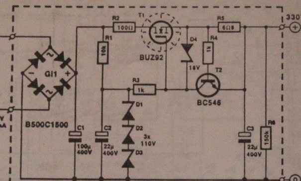
Rectifier-stabilizer of the anode voltage, used in both amplifiers, only tuned to different voltages.Here, by the number and operating voltage of the zener diodes, the output voltage of the stabilizer is set. Transistor T1 - almost any high-voltage corresponding structure, diodes are shunted by film or ceramic capacitors at 100 ... 150nF, 630V
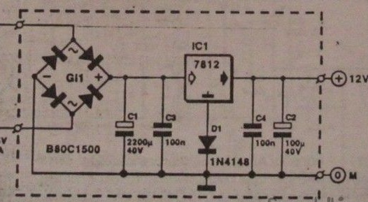
The voltage stabilizers of the filament of the vinyl corrector lamps are 7806, with an additional silicon diode in the common wire circuit (gives a voltage gain of ~ 0.3 volts at the input of the stabilizer). Rectifier - a bridge of Schottky diodes, also shunted by capacitors (optional). Lamps of a power amplifier (6E5P) in terms of incandescence, consume much more current than 6H9 to reduce it, a series connection of the filaments of two lamps is applied and integral stabilizers 7812 with diodes in the common wire circuit are used.
Sufficient radiators and suitable transformers have been selected. To power the filament lamps of the power amplifier, a standard VT was found, for the anode voltage of the TA. Overall power turned out to be with a fair margin, which is not bad - the transformers do not buzz, do not heat up. The presence of a large number of windings made it possible to select the desired voltage at the input of the stabilizer so as not to overheat the control transistor. It was also possible to enter standby mode - with a reduced filament voltage and anode, to save lamp life.
The power transformer of the vinyl corrector is a combined TAN, it has both high-voltage windings for anode voltage and low-voltage high-current for heat. A large number of windings also made it possible to organize a standby mode.
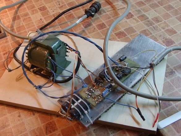
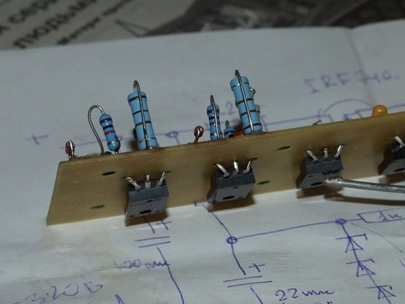
In accordance with the dimensions of the radiators, printed circuit boards for small elements of rectifiers and stabilizers have been developed. Elements requiring cooling - stabilizer microcircuits and field effect transistors, in TO-220 cases, are mounted upside down and pressed by a metal flange through a mica gasket to the radiator. On the side of the board "to the radiator" there are no conductive paths - the entire installation is performed on the opposite side of the board, the "pads" are formed supporting pads for the conclusions of small elements. Thus, the installation resembles a volumetric one, the risk of shorting to a cooling radiator is not great.
In a similar way, the stabilizer of a power amplifier was mounted on the G-807.
There are two radiators in total, each one has a mounting plate with a full set of voltages for one device - perhaps the solution is not very successful in terms of the layout of the power supply as a whole, however, it was possible to work conveniently when prototyping and setting up devices when the power supplies were not assembled in single housing.
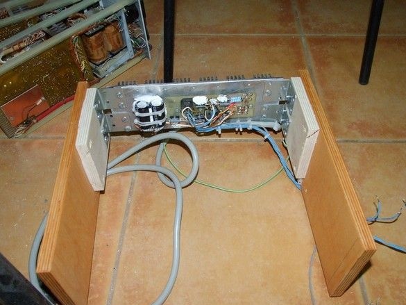
The design of the case is peculiar - the radiators are placed in the rear open part of the unit, while the boards with high-voltage elements are slightly recessed, it is practically impossible to touch them with your hand, especially considering the location of the power supply in the niche of the rack.
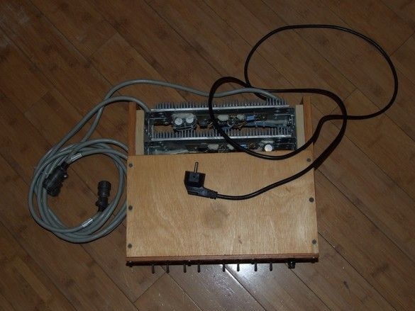
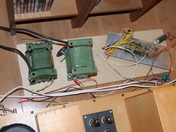
The block case is assembled on self-tapping screws, the walls are made of thick 15mm plywood. In the front of the unit, transformers are fixed to the bottom of the unit with screws. The center of gravity turned out to be shifted to the front panel, but it’s convenient - for any manipulations with the controls, a separate unit does not need to be held.
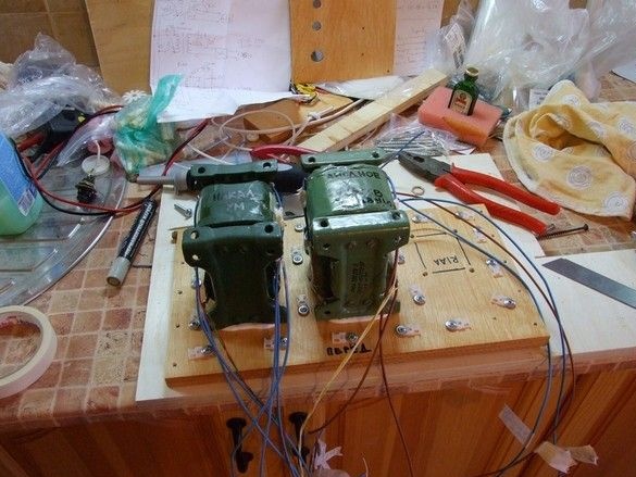
Around the transformers, such witch circles, special platforms are installed for attaching nylon ties to them. Given the large number of wires and harnesses from them, the number of sites is not excessive - practice has shown that almost all of them were involved.
The connection of the power supply to the amplifiers is made with a thick multicore cable. A large number of cores made it possible to form the necessary groups depending on the transmitted current and the purpose of the cable.
In the process of installation, of this kind, it is imperative to apply, at least technological marking, this greatly facilitates life.
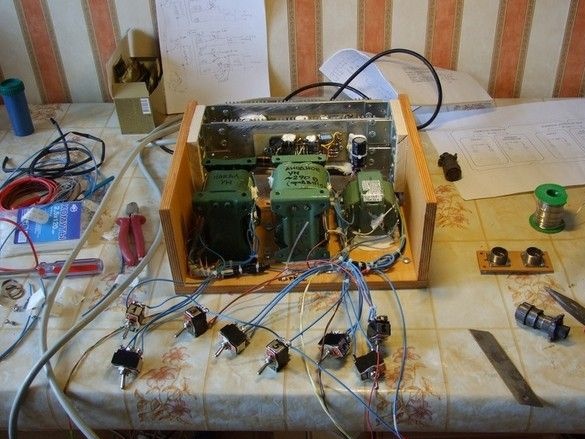
Power supply without cover and front panel. Amplifiers were assembled some time ago and worked with open mock-ups of their power supplies. In that form, it was very convenient to make adjustments - select the voltage, control the work and so on. Now, only a functional check and elimination of possible installation errors.
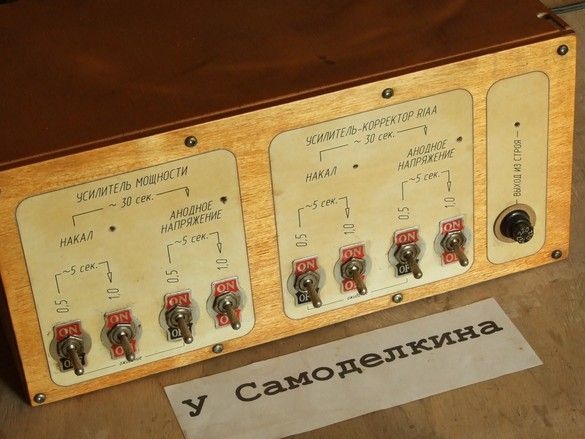
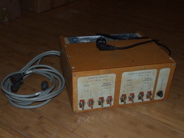
The front panel of the block was sawn out of thin plywood, after varnishing, glued onto it were blocks drawn in AutoCAD and printed on the printer with explanatory inscriptions. To protect the labels, the stickers are also coated with a layer of varnish. In appropriate places, holes were drilled for installing toggle switches, neon indicator lights and fuse pads. In parallel to the block, a neon bulb is also installed, indicating a blown fuse.
The practice of prolonged use of the unit has shown that the unit is reliable, has all the specified electrical parameters. The disadvantages include some complexity switching modes - toggle switches. If you intend to make a similar device for use "in the wrong hands", it is better to use a special device that implements the necessary algorithms automatically using electromagnetic relays. In addition, I was faced with the need for separate power supplies - for each device, however, it was a "contingency mode" - when moving.