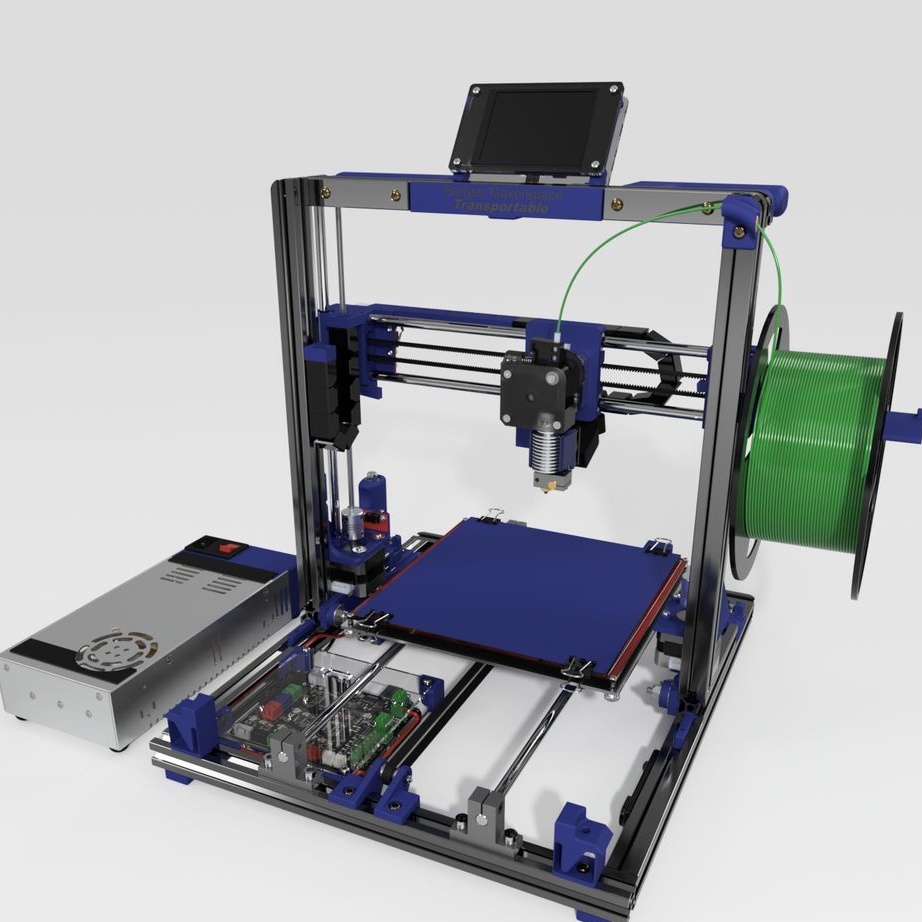
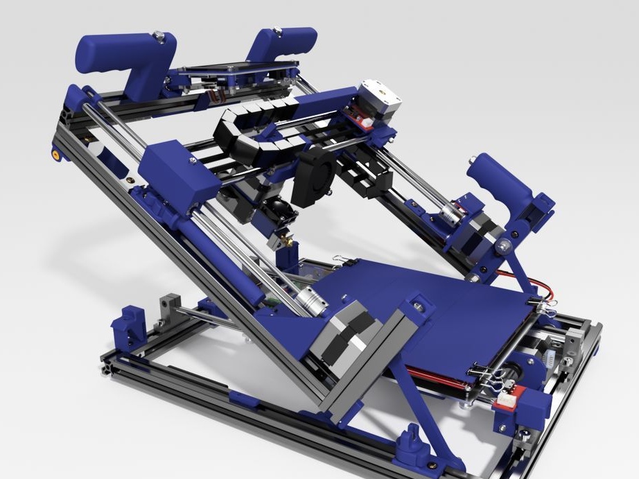
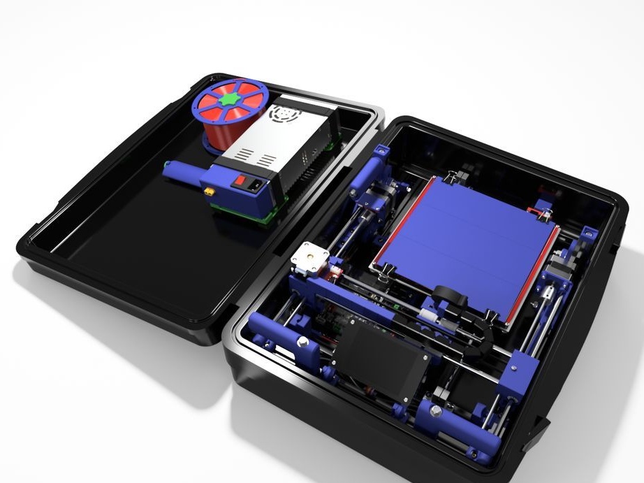
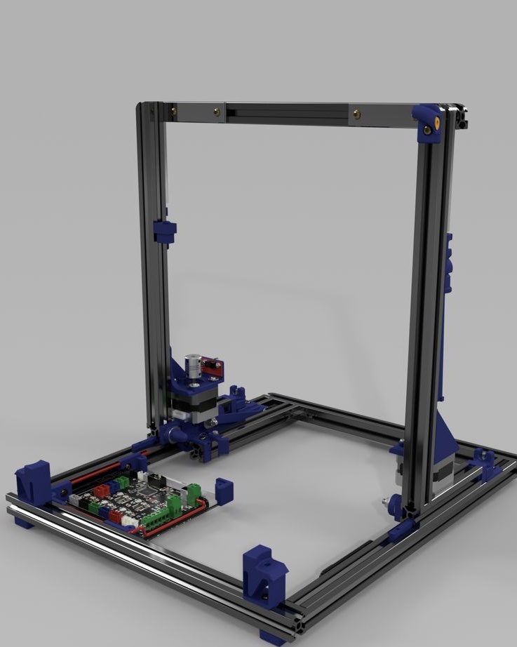
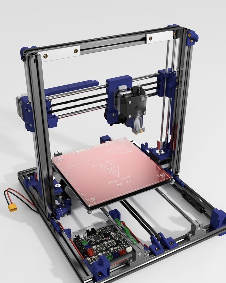
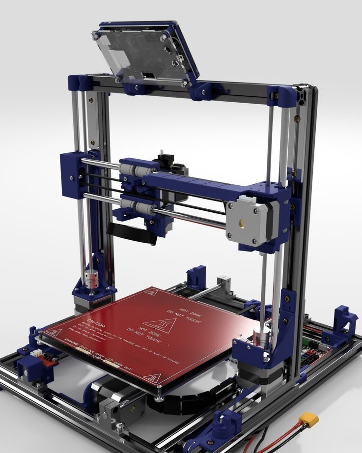
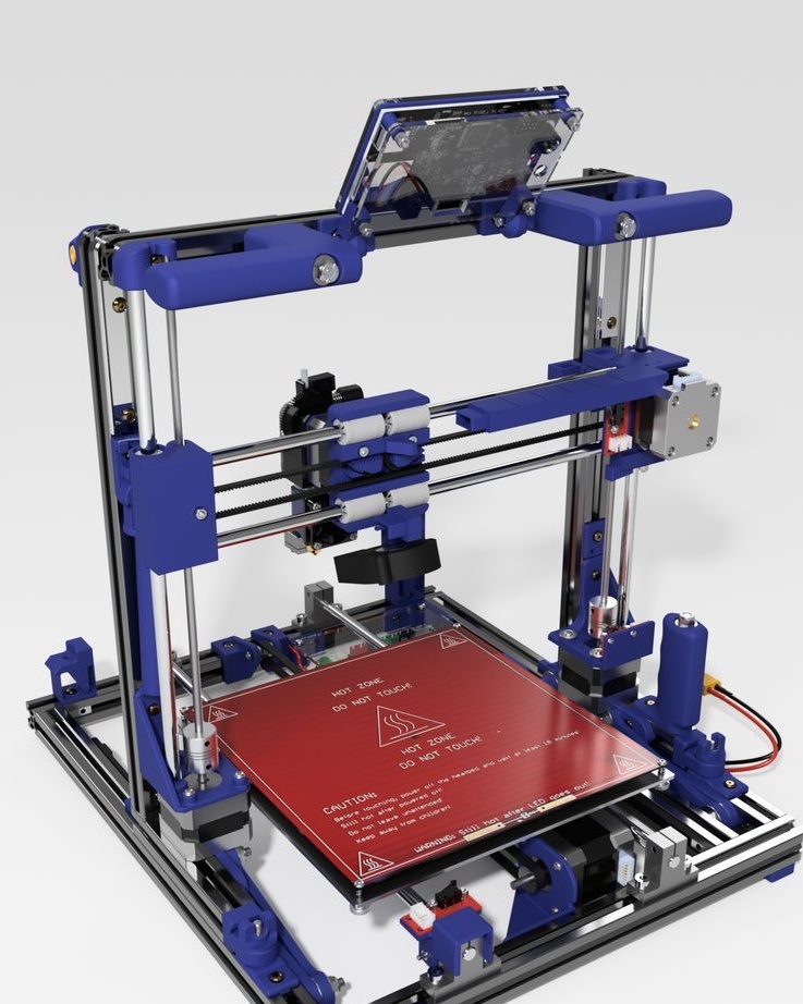
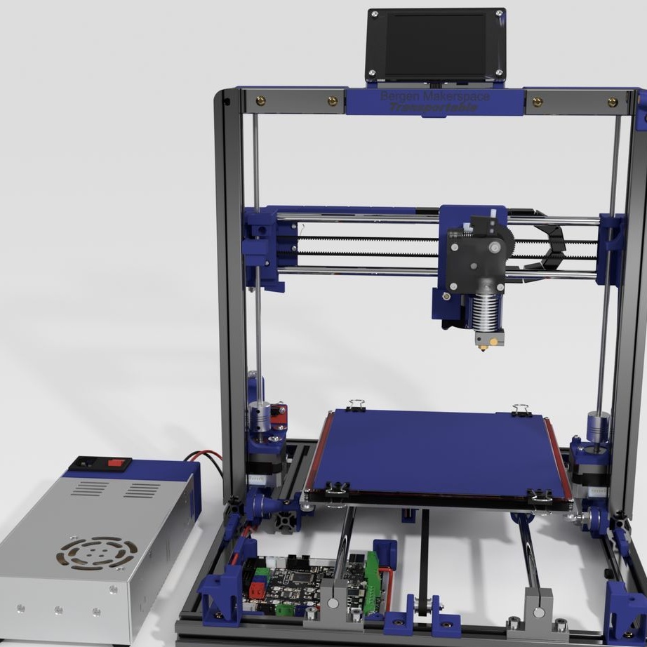
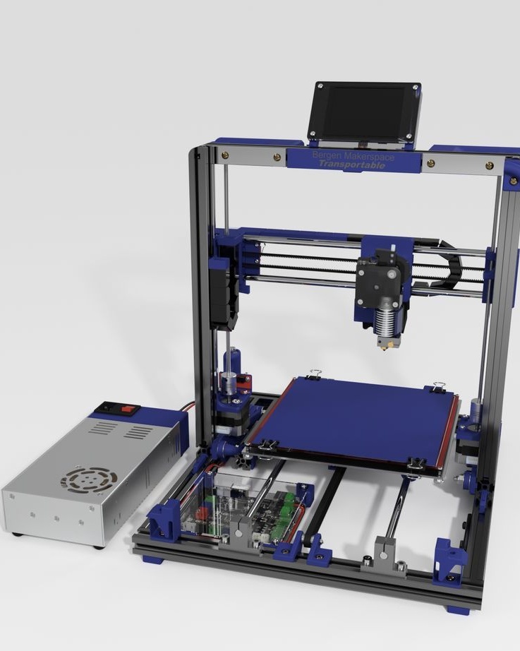
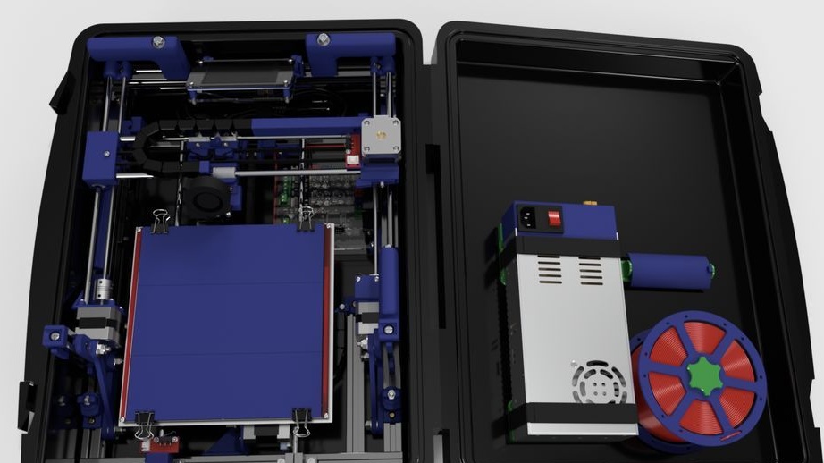
A 3D printer that can be quickly disassembled, moved to another location and quickly mounted on a new one, was made by a Master from the USA. Disassembled 3D printer size 200 mm x 200 mm x 175 mm. First, let's watch two videos.
As you can see, the device is easily disassembled and placed in a carrying case.
Step One: Tools and Materials
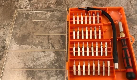
In this article, you will have to move away from the traditional listing of tools and materials. The author provides the entire list of materials before each step and, in order not to confuse anything, we will adhere to his style. From the tool, he uses a screwdriver with a set of bits, a soldering station, a tool for cutting aluminum profiles, etc. Some parts are printed on a 3D printer or cut by CNC.

Step Two: Print Files
In this step, the wizard provides access to files for printing on a 3D printer and cutting on CNC.
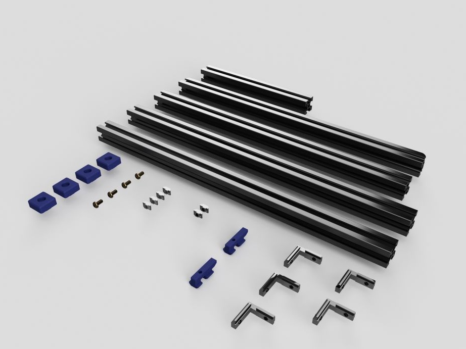
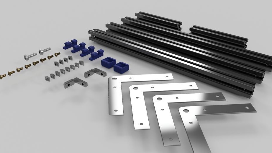
Step Three: Cutting and machining aluminum profiles, printed mounting plates and L-brackets
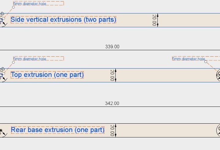
Aluminum Profile 2020.
For the project, it is necessary to prepare a profile of the following length:
2 pcs - 365 mm
3 pcs - 342 mm
2 pcs - 339 mm
1 pc - 173 mm
2 pcs - 119 mm
After preparation of the profile, it is necessary to process it and drill holes as indicated in the drawing above. The holes are drilled on two profiles with a length of 342 mm and one 339 mm.
Corner brackets.
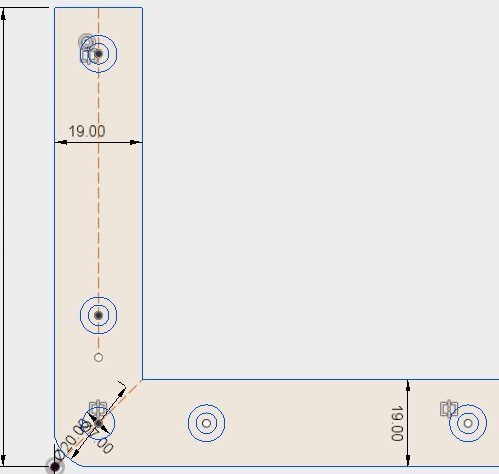
The master purchased corners in a hardware store. The size of the corner is 100 * 100 * 19. According to the drawing, I finished the corners.
Aluminum plate.
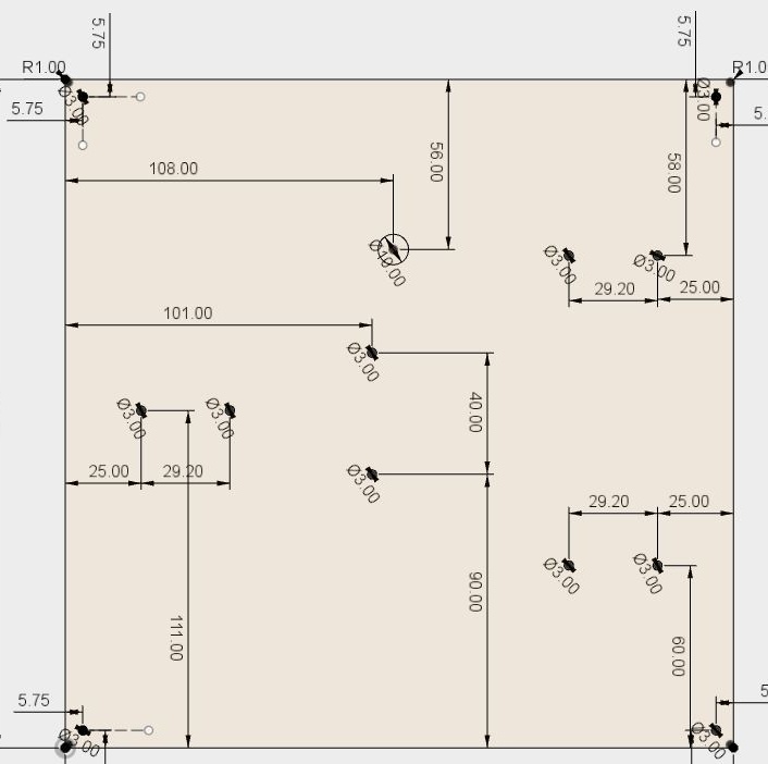
The plate has a size of 220 * 220 mm and a thickness of 2.5 mm.
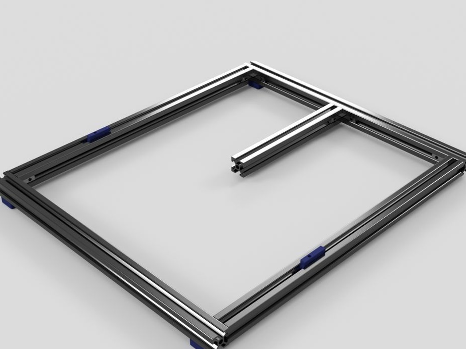
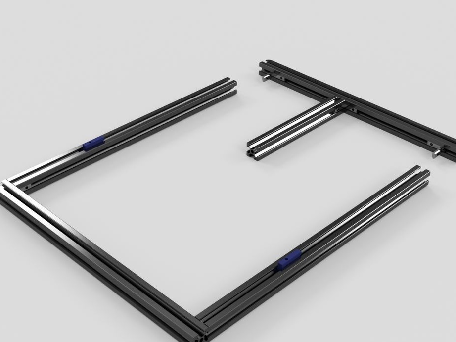
Step Four: Bottom Frame
To assemble the frame, you need the following materials:
- aluminum profile 365 mm - 2 pcs;
- profile 342 mm - 1 pc;
- profile 342 mm - 1 pc;
- profile 119 mm - 1 pc;
- printed part No. 31 -4 pcs .;
- printed part No. 30 - 2 pcs .;
- brackets for aluminum profile - 5 pcs;
- fasteners;
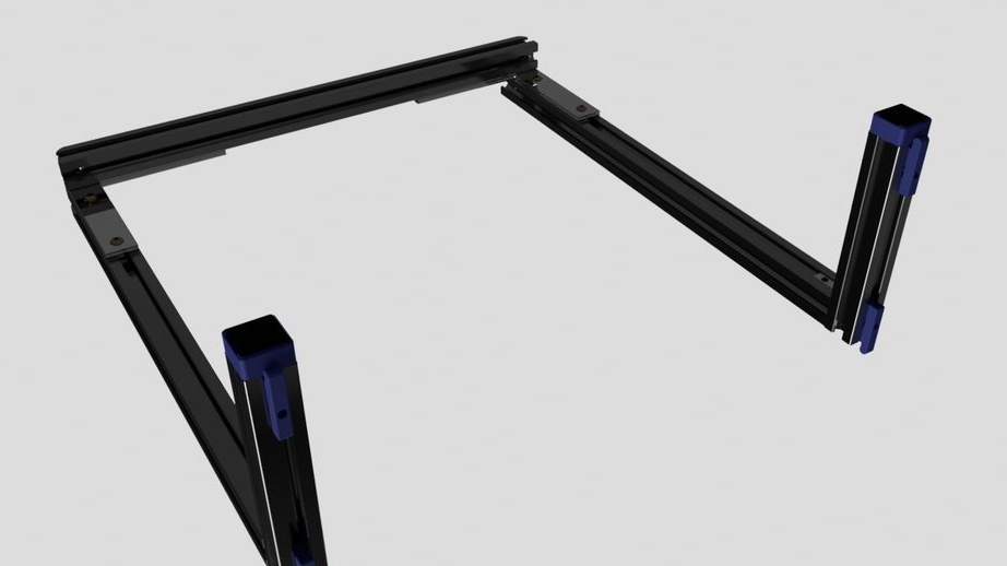
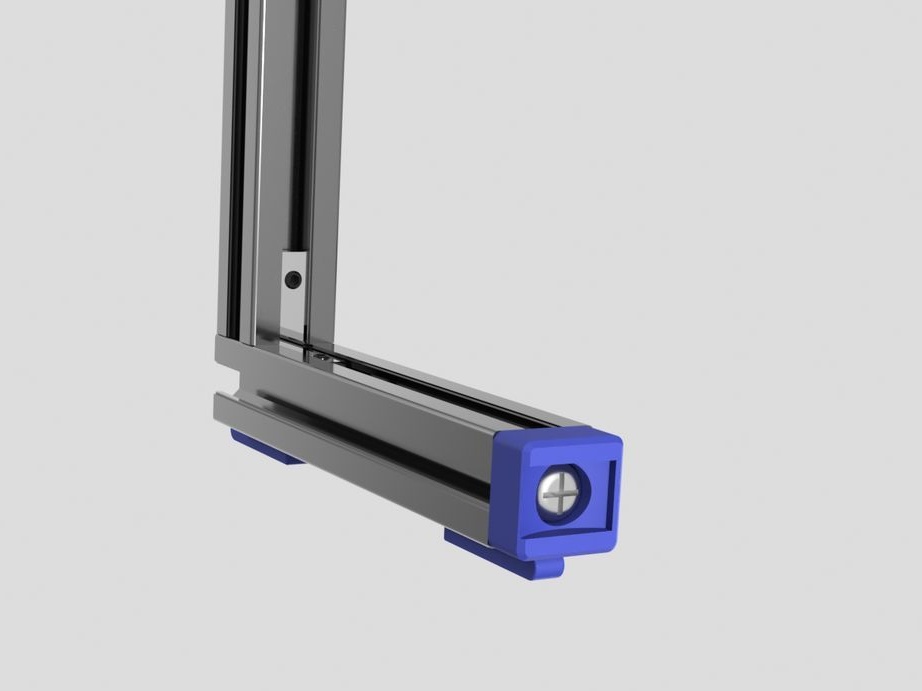
Step Five: Vertical Frame
Then collects a vertical frame. To do this, he needed:
- aluminum profiles 339 mm - 2 pcs;
- profile 342 mm - 1 pc;
- profile 119 mm - 2 pcs;
- L-brackets - 2 pcs;
- brackets for aluminum profile - 2 pcs;
- printed part No. 35 - 2 pcs;
- printed part No. 32 - 4 pcs;
- fasteners;
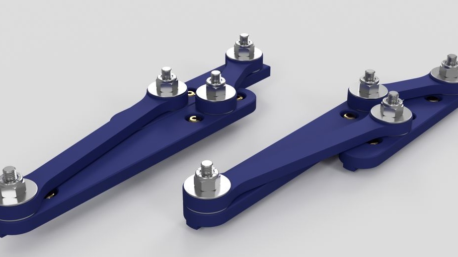
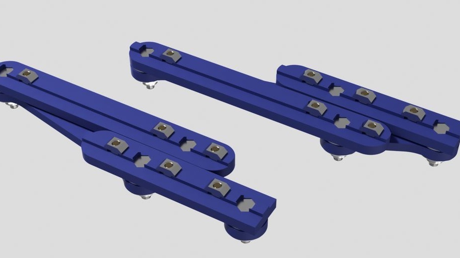
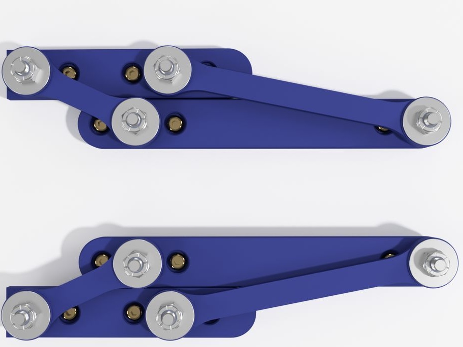
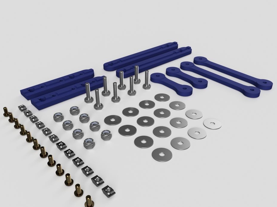
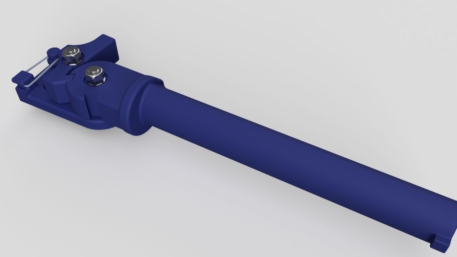
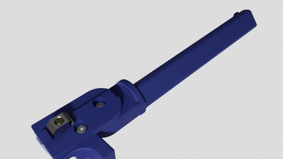
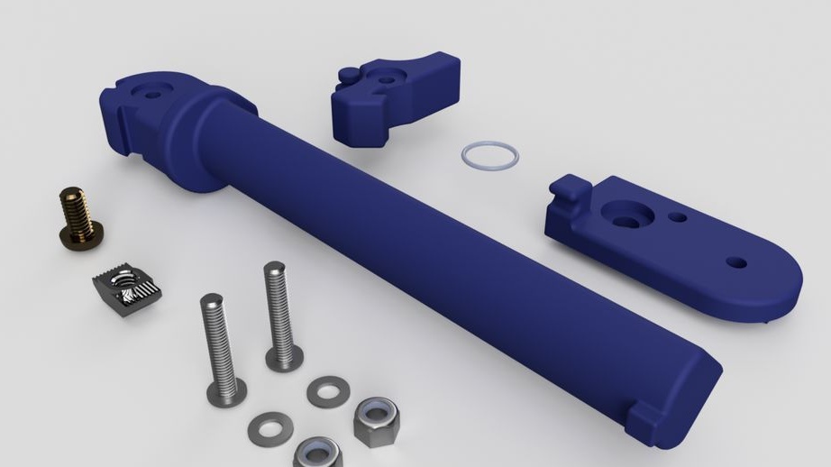
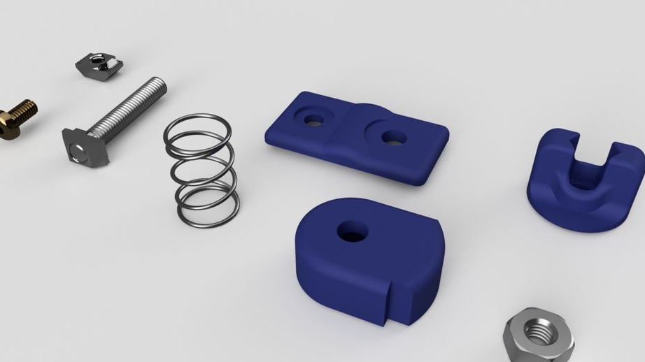
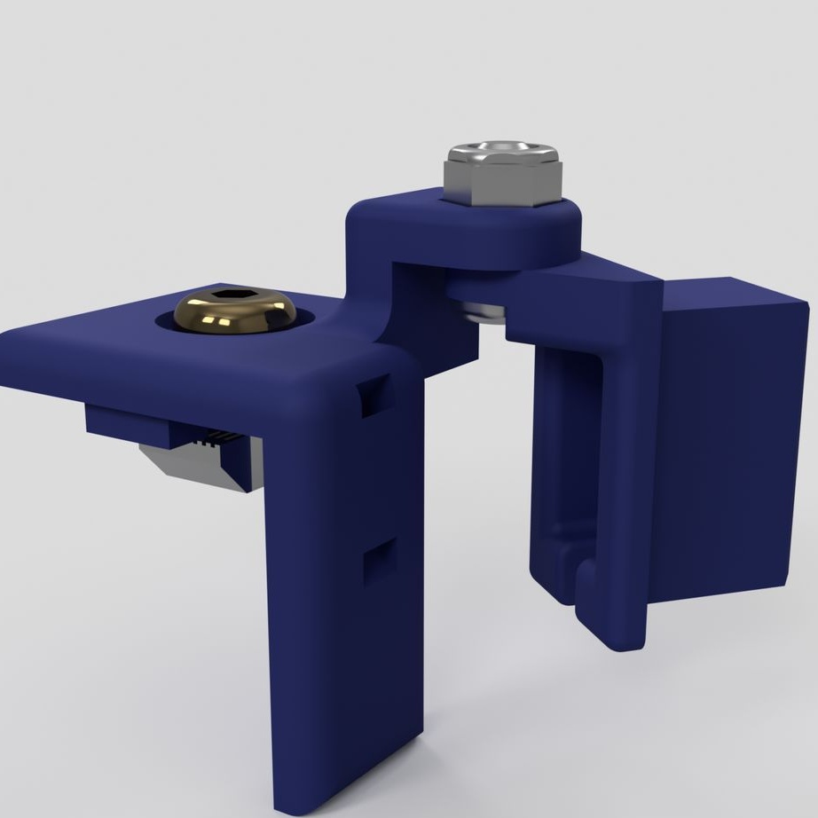
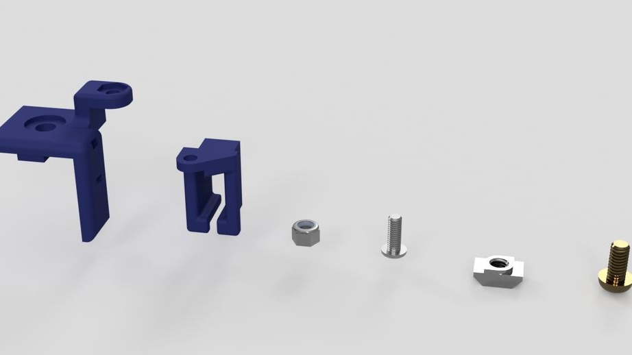
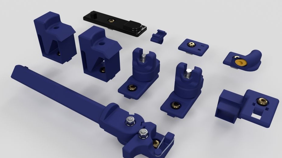
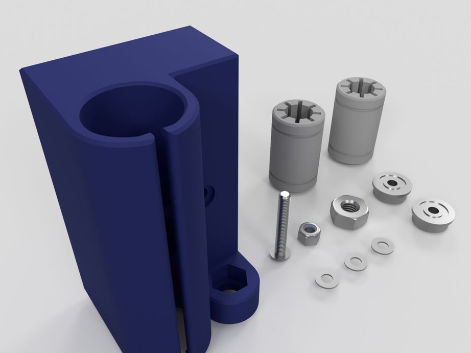
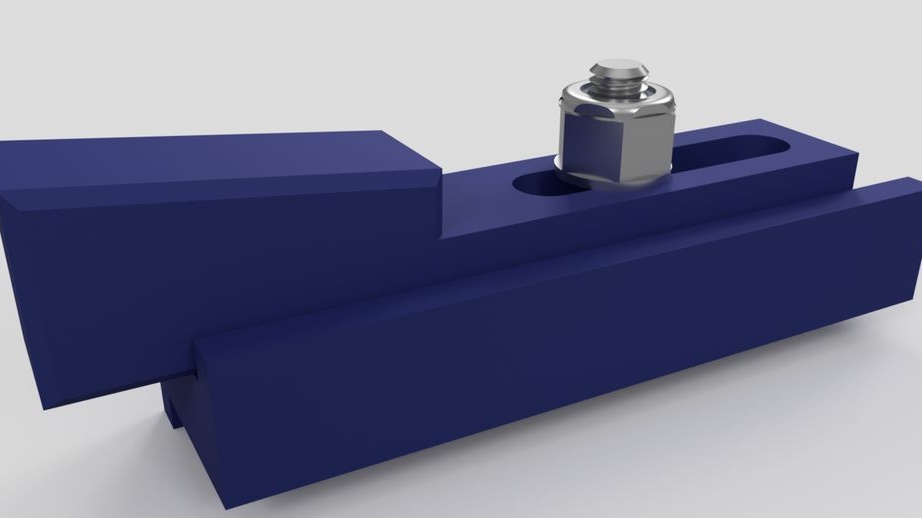
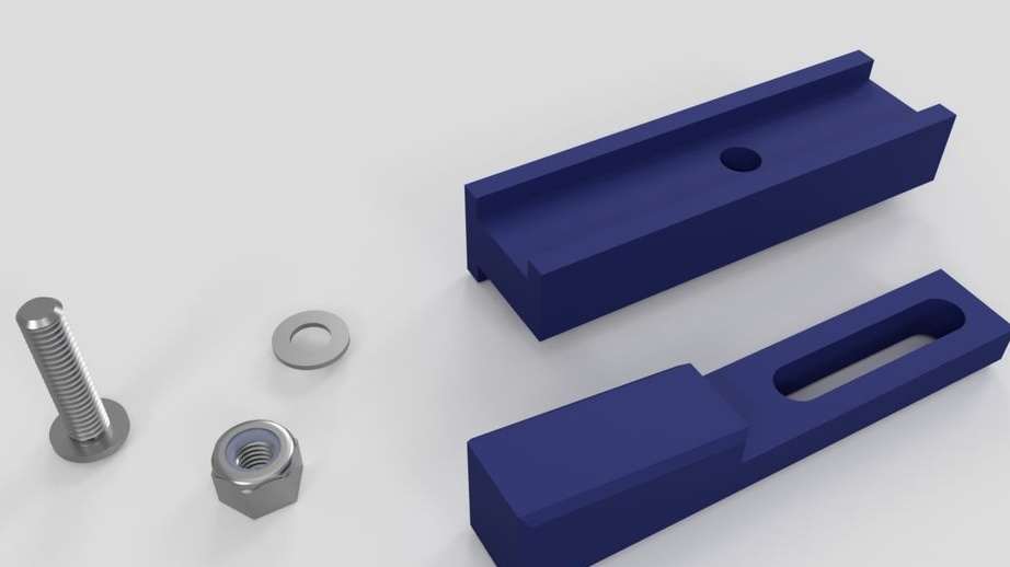
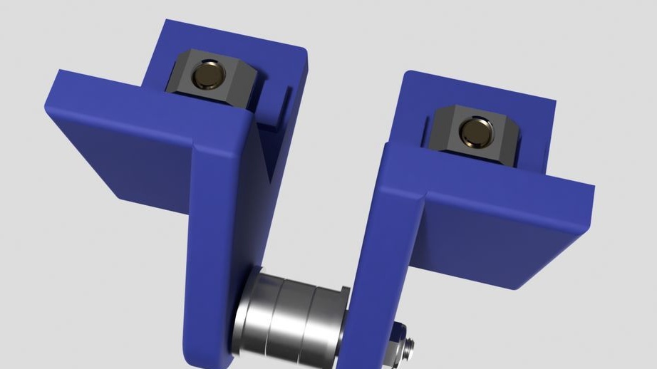
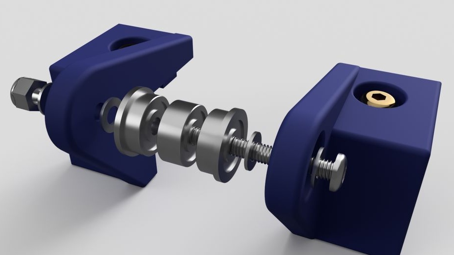
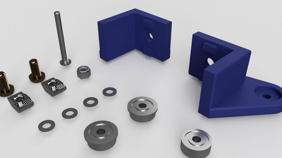
Step Six: Swivel Assembly
The following parts are needed to assemble the hinges:
- washers 16 pcs;
- bolts with nuts M5 20 mm - 8 pcs;
- bolts with nuts M4 8 mm - 12 pcs;
- printed part No. 10 - 2 pcs;
- printed part No. 11 - 2 pcs;
- printed part No. 12 - 2 pcs;
- printed part No. 13 2 pcs;
Assembles a hinge. Tightens the nuts taking into account the operation of the mechanism.
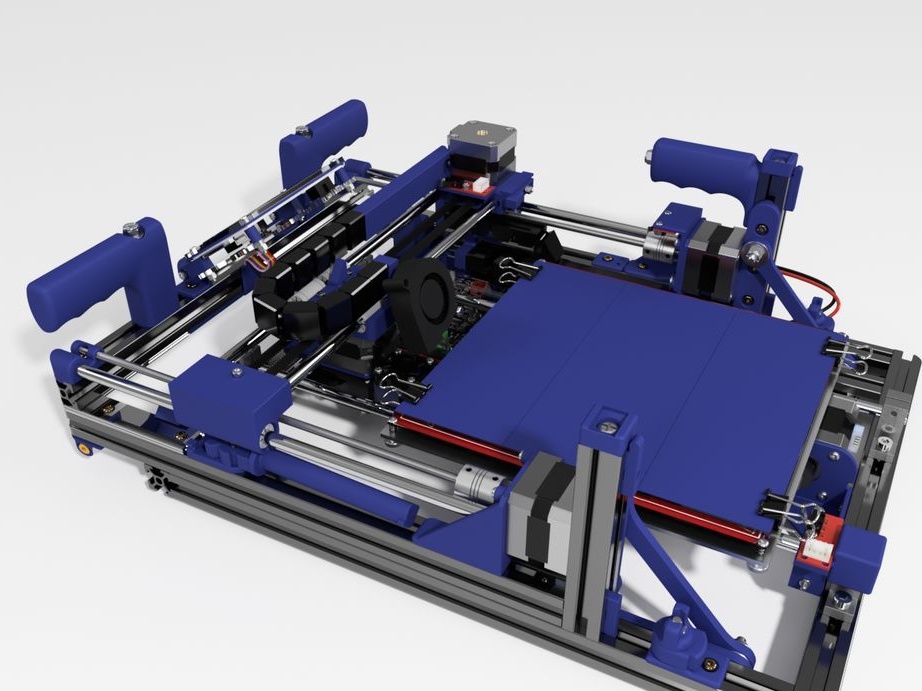
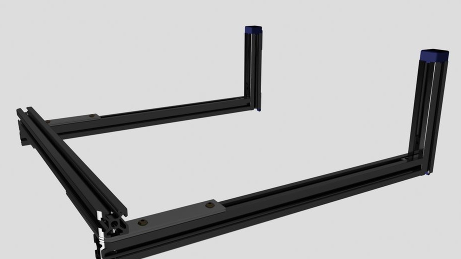
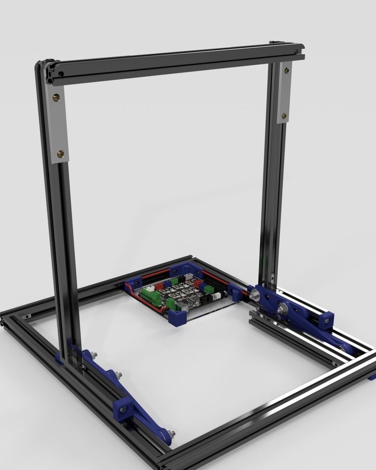
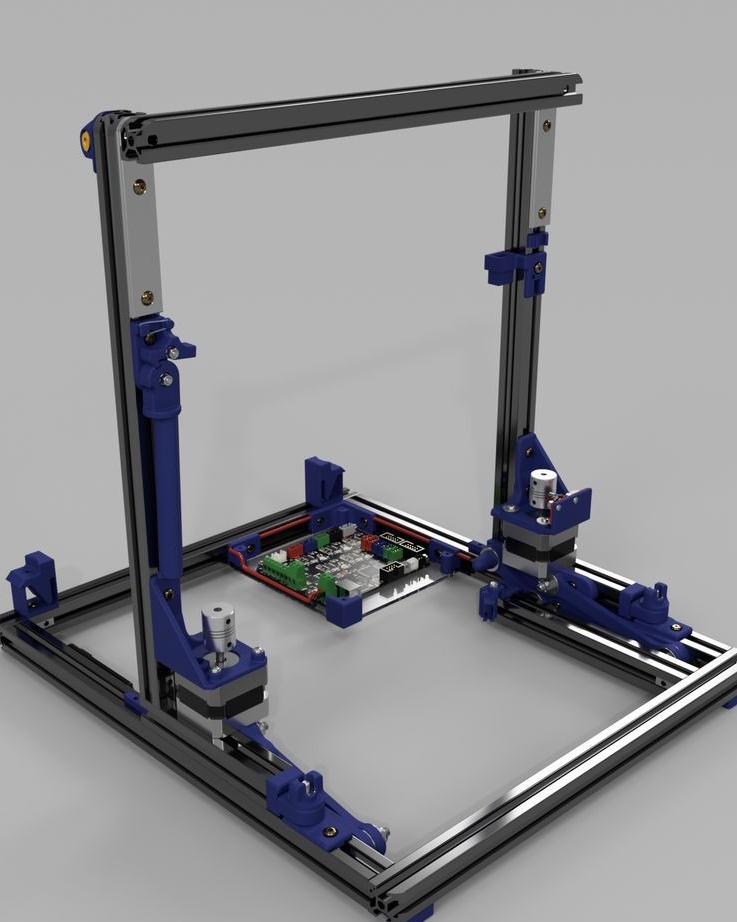
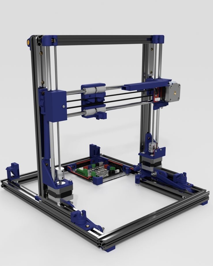
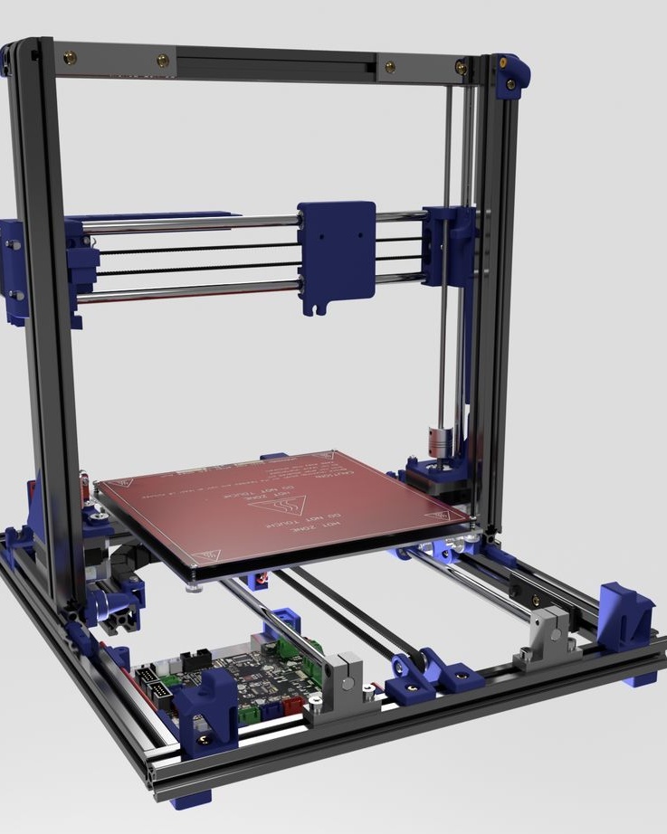
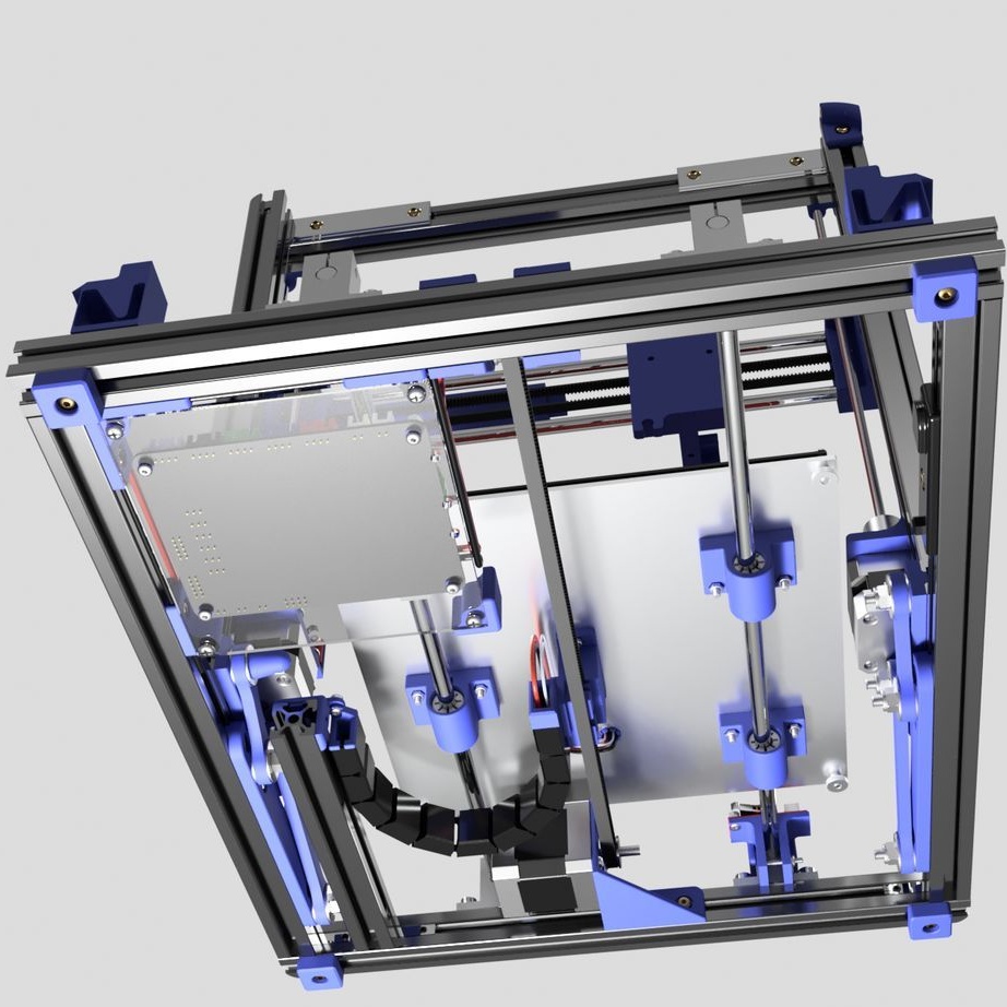
Seventh step: frame assembly
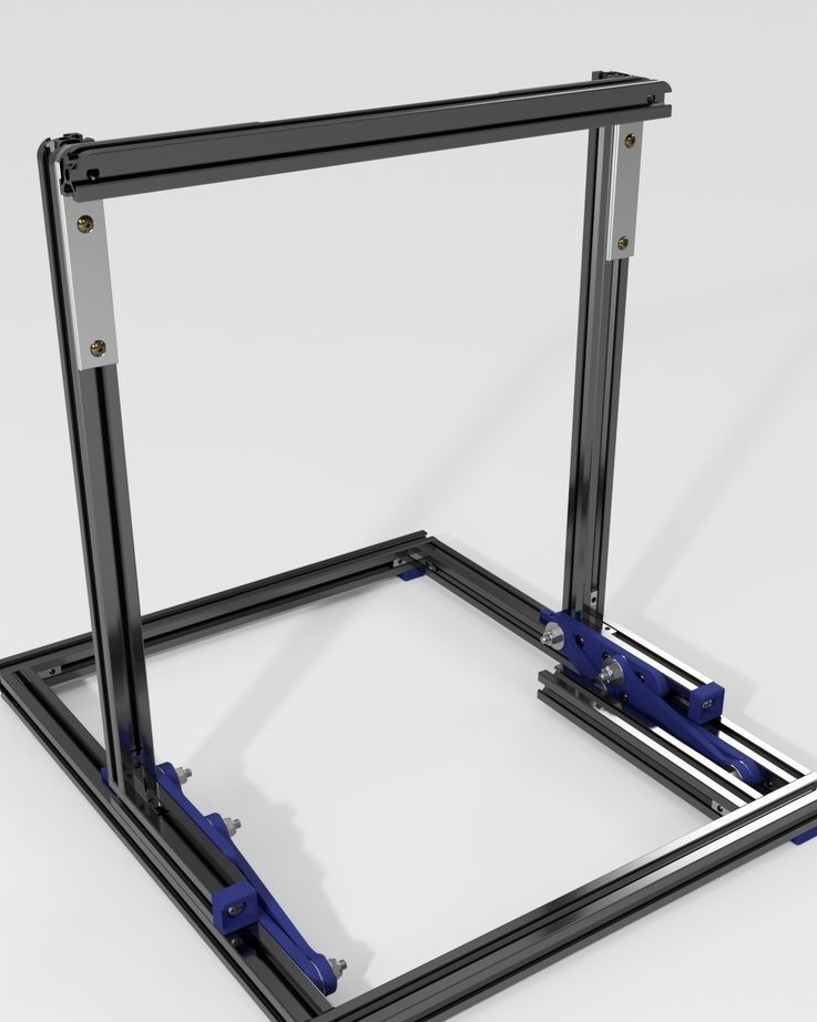
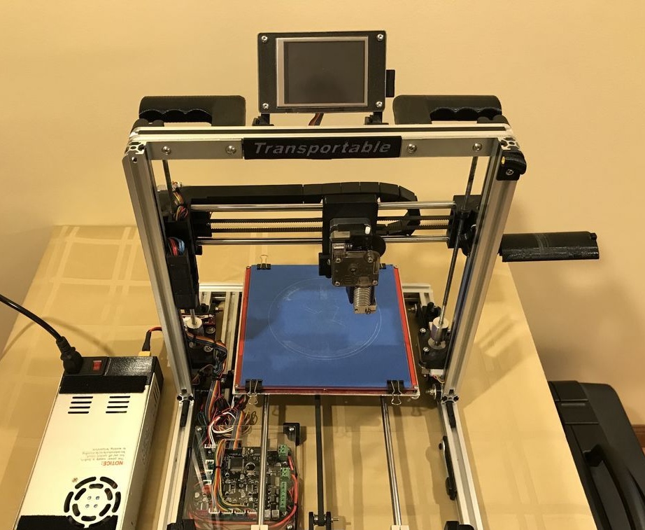
Now the upper and lower parts need to be put together. As you can see in the photo, the assembly requires a vertical and lower frames and two hinged mechanisms.
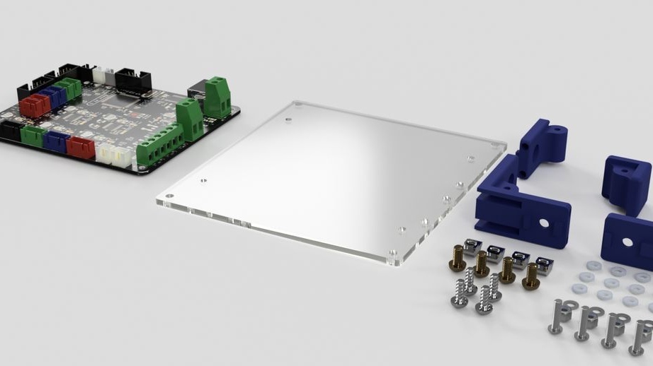
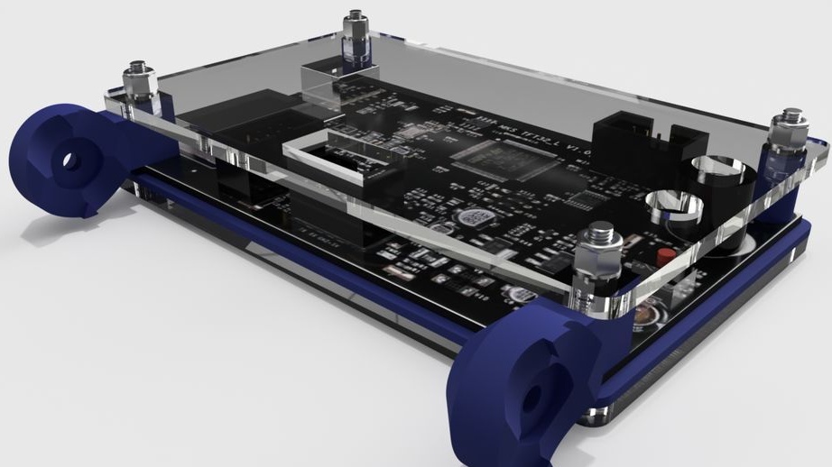
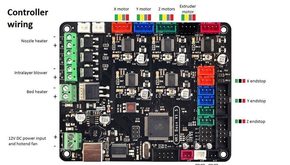
Step Eight: Controller Board
To install the board you will need the following materials:
-controller board MKS BASE V1.5;
- Acrylic;
- 740 mm black wire (diameter 1.2 mm);
- 740 mm of red wire (diameter 1.2 mm);
- connectors;
- Heat-shrink tubing;
- printed part No. 1 - 1 pc;
- printed part No. 2 - 1 pc;
- printed part No. 3 - 2 pcs;
Cut acrylic sheet and drill mounting holes. Fastens the board on acrylic. Installed wire holders. Paved wire.
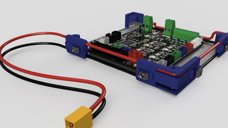
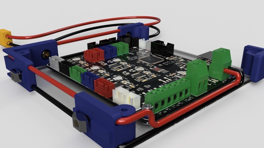
After assembly, mounts the board on the frame.
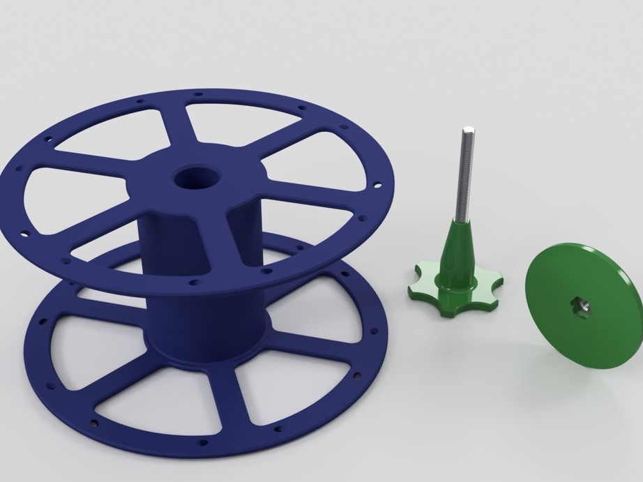
Step Nine: Coil Holder
The following parts are needed for the coil holder:
- printed part No. 7 - 1 pc;
- printed part No. 8 - 1 pc;
- printed part No. 9 1 pc;
- rubber ring;
- fasteners;
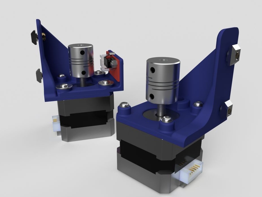
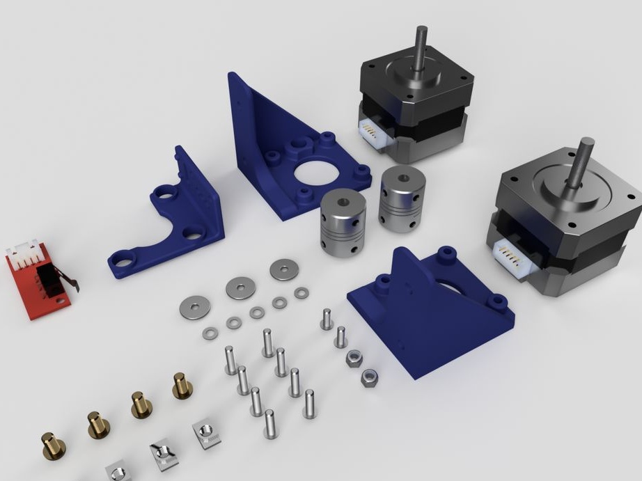
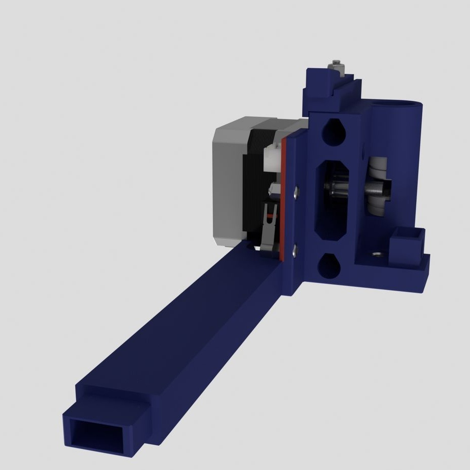
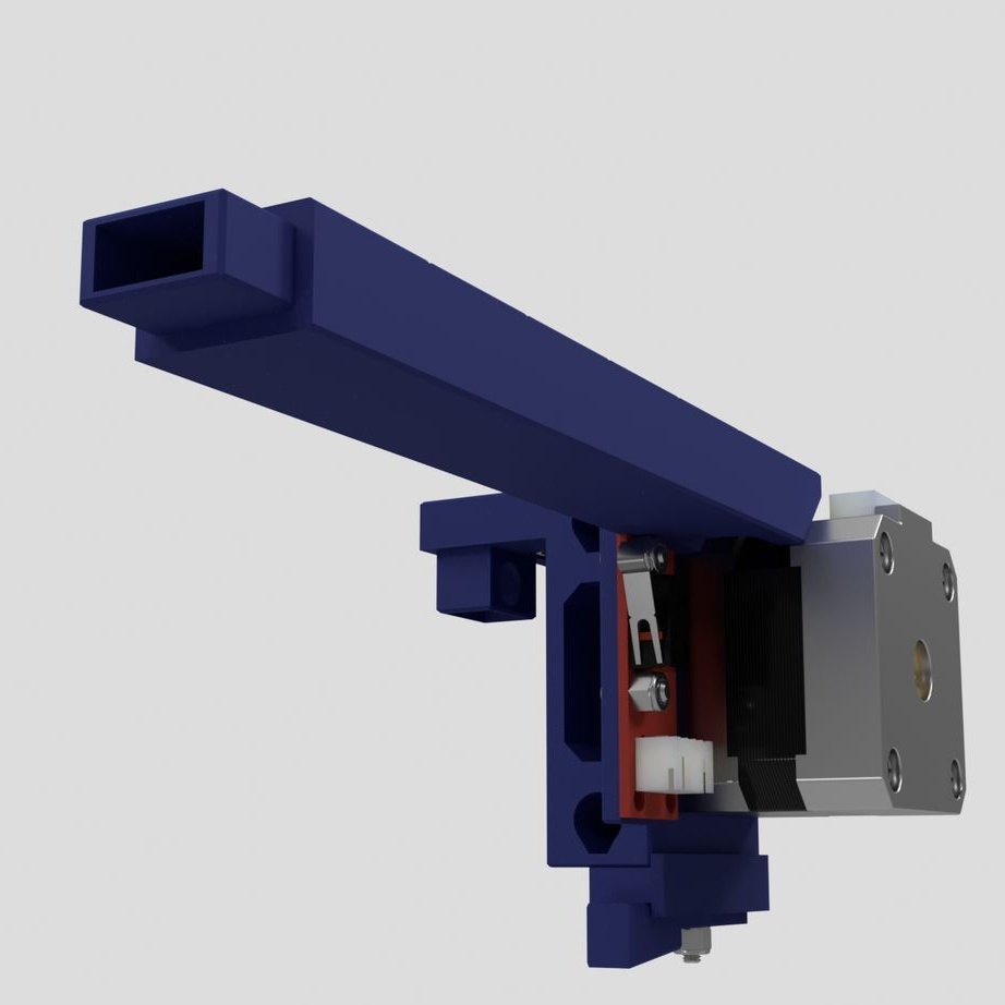
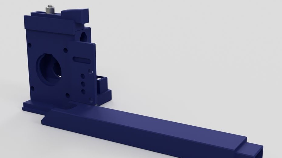
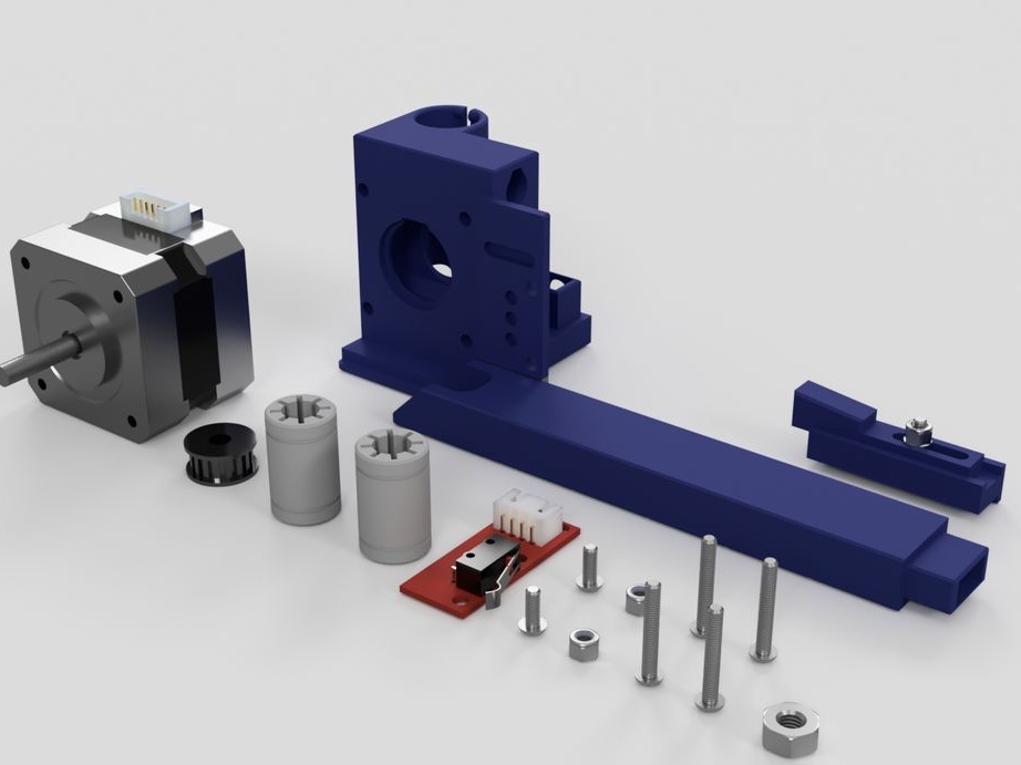
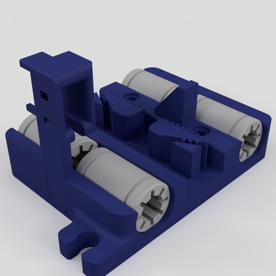
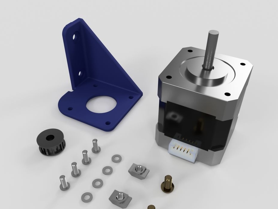
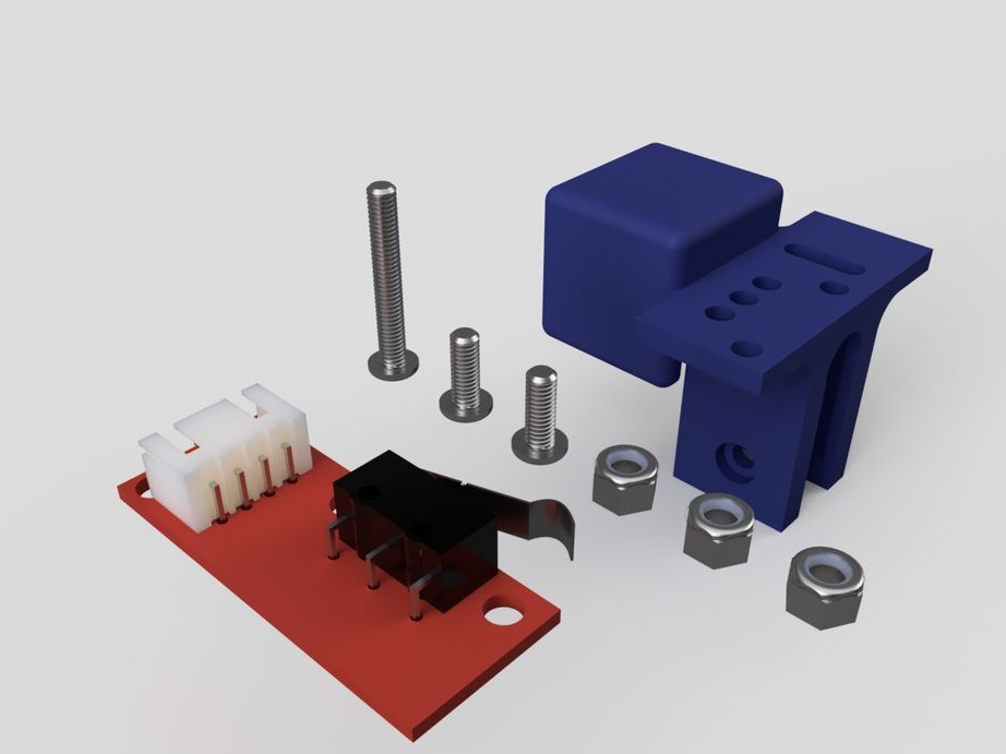
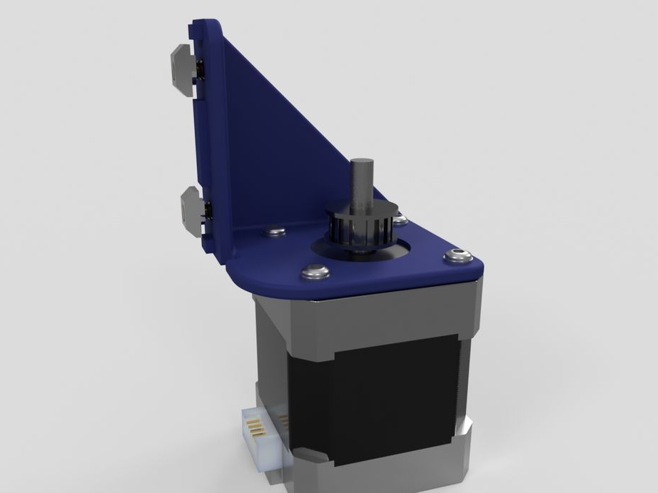
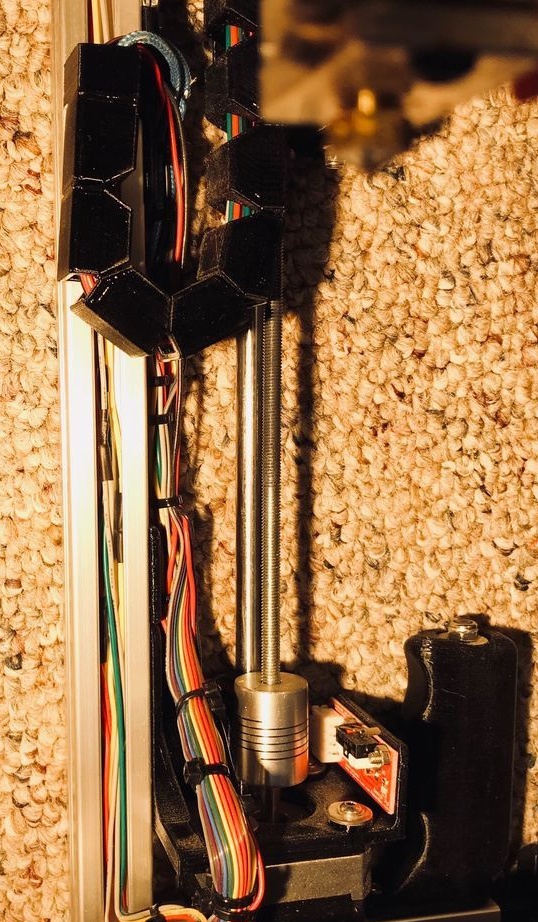
Step Ten: Motors
To install the engines, the master used the following details:
- two stepper motors NEMA17;
- two 5 mm couplings with screws;
- limit switch;
- printed part No. 36 - 1 pc;
- printed part No. 37 - 1 pc;
- printed part No. 46 - 1 pc;
Collects nodes as in the photo.
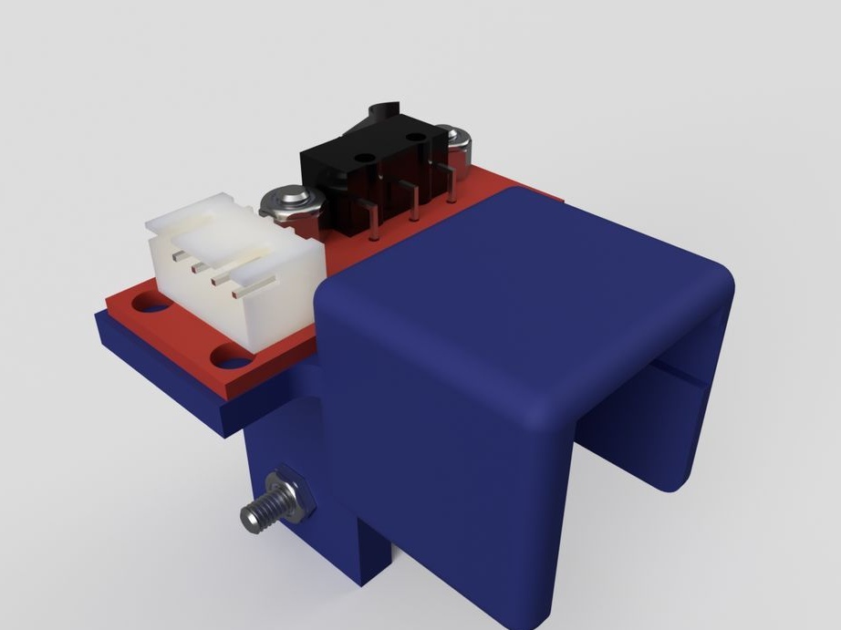
Step Eleven: Rear Retainers
Assembling the clips does not cause any difficulties. All actions are shown in the photo below. Details necessary for clamps:
-Two bolts with nuts M5 x 30 mm;
- two springs;
- two bolts with nuts M4 x 8 mm
- printed part No. 4 - 2 pcs;
- printed part No. 5 - 2 pcs;
- printed part No. 6 - 2 pcs;
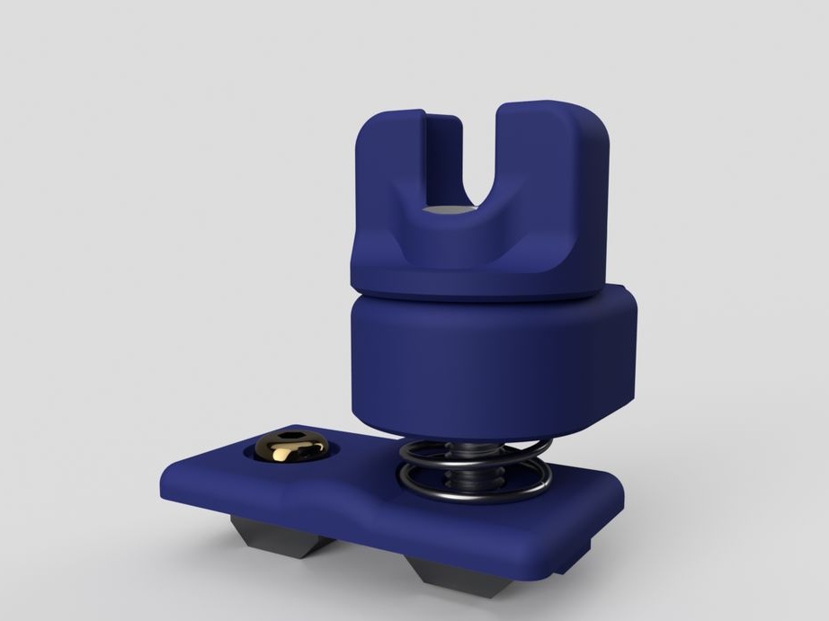
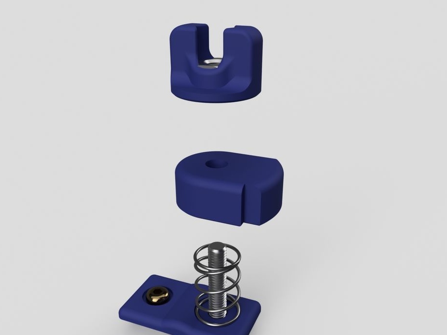
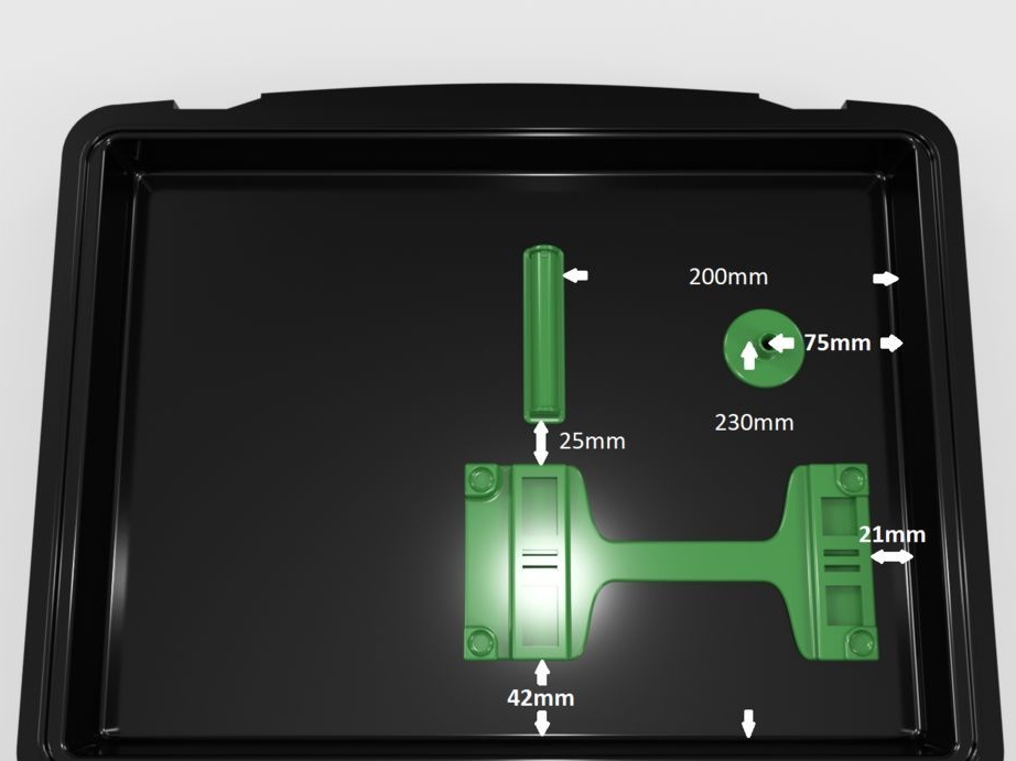
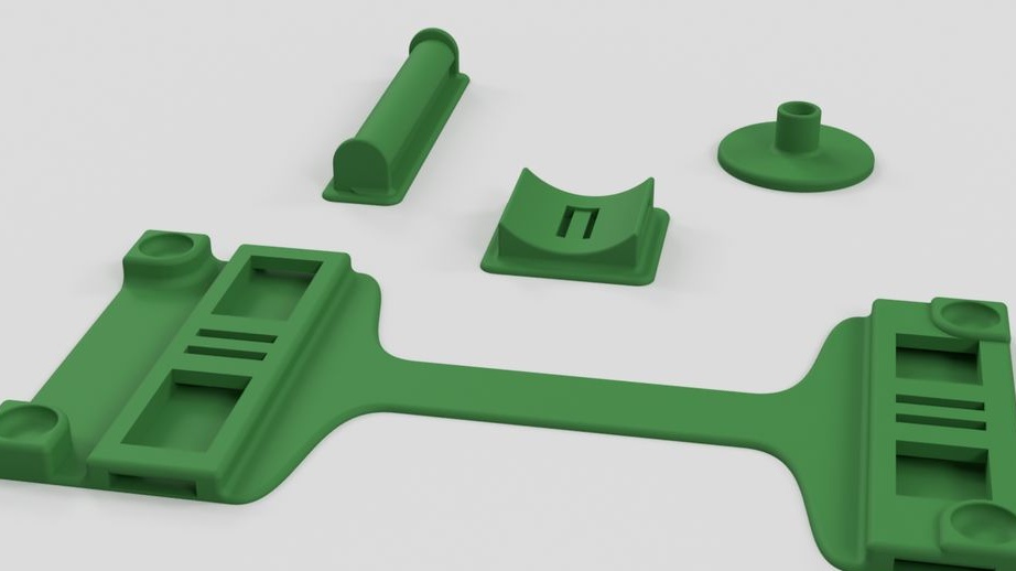
Step Twelve: Holder
The holder consists of the following parts:
- bolt with nut M3 x 8 mm;
- bolt with nut M4 x 8 mm;
- printed part No. 33 - 1 pc;
- printed part No. 34 - 1 pc;
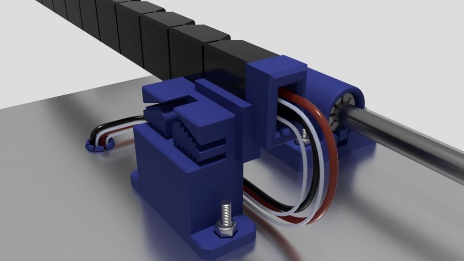
Step Thirteen: Assembling Parts
Next, the wizard sets some details on the frame. List of necessary;
- coil holder;
- cable holder;
- back latches - 2 pieces;
- front latches (printed part No. 43) - 2 pcs;
- thread guide (printed part No. 39);
- teflon tube;
- cable fastening (printed part No. 40);
- printed part No. 41;
- printed part No. 42;
- nuts with bolts 5 mm M4 x 8 mm - 5 pcs;
As you can see in the photo, the installation is simple. Before installation, insert the tube into the thread holder and cut it at an angle.
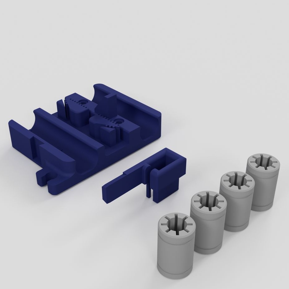
Step Fourteen: Assembling Nodes
In this step, consider assembling multiple printer nodes. Below the photo will be a list of details for each node.
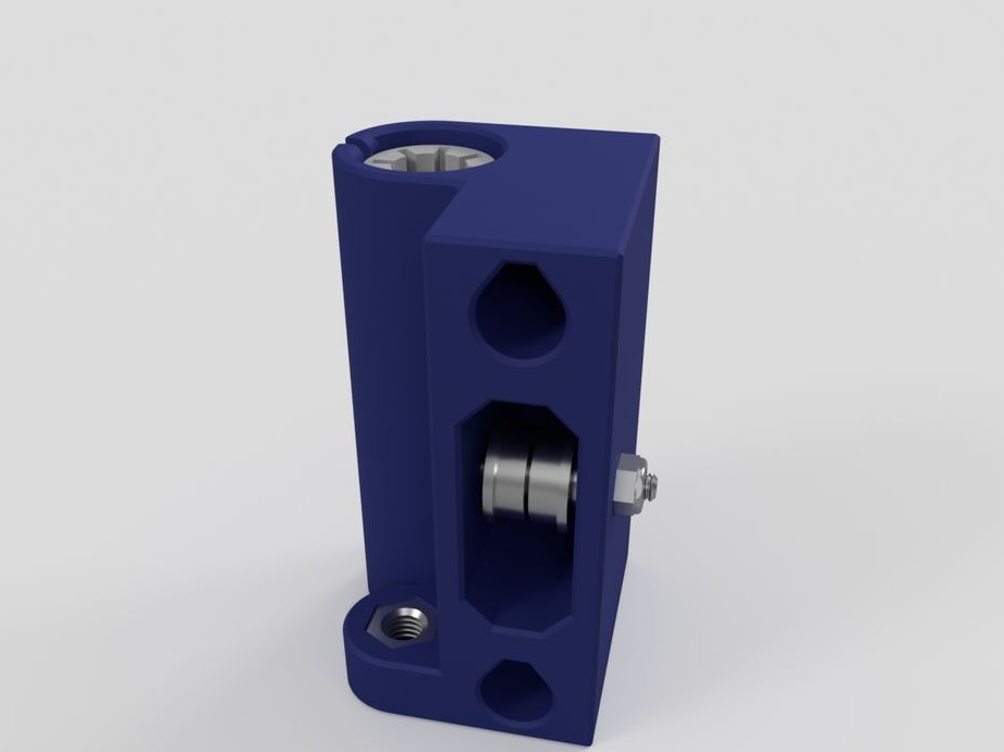
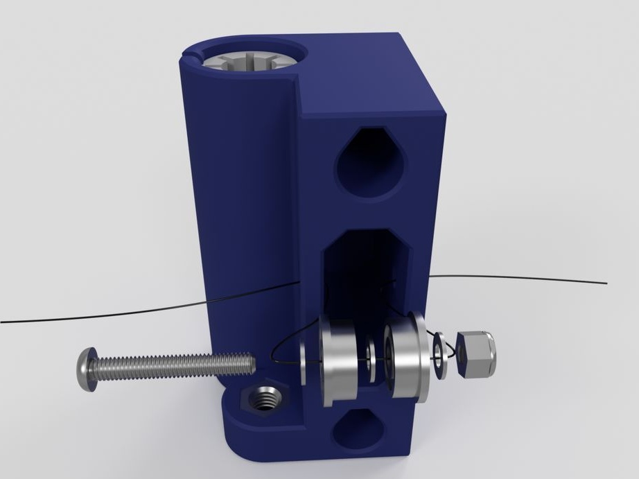
- bolt with nut M3 x 20 mm;
1 x Locknut M3
- two bearings;
- three washers M3;
- nut M5;
- two bearings LMU88;
- printed part No. 16
- bolt with nut and washer M3 x 12 mm;
- printed part No. 44;
- printed part No. 45;
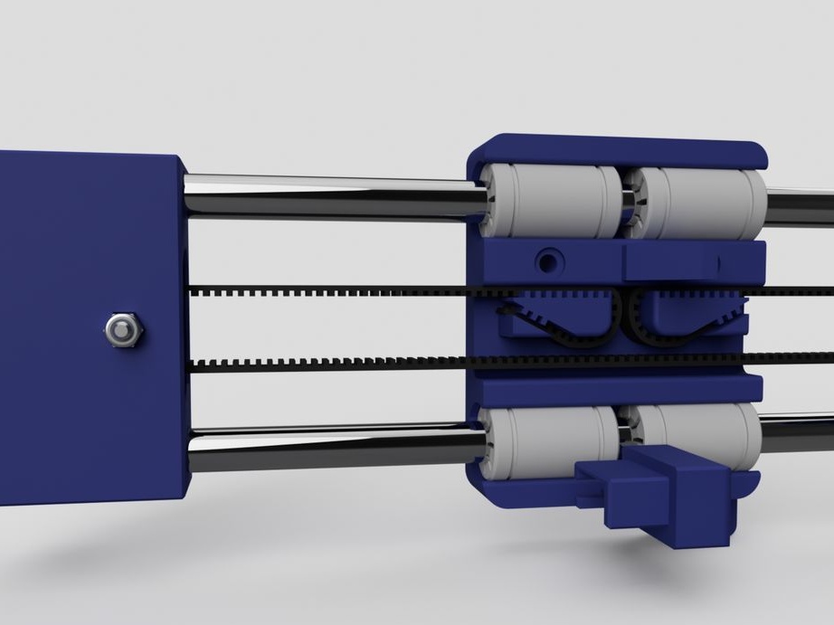
Step Fifteen: X-axis
Let's start with the engine.
Parts list.
- four bolts M3 x 20 mm;
- two bolts with nuts M3 x 8 mm;
- nut M5;
- two bearings LMU88;
- 20 toothed pulley with screws;
- NEMA17 stepper motor;
- limit switch;
- printed part No. 17;
Further the carriage gathers.
- four bearings LMU88;
- printed part No. 15;
- printed part No. 14;
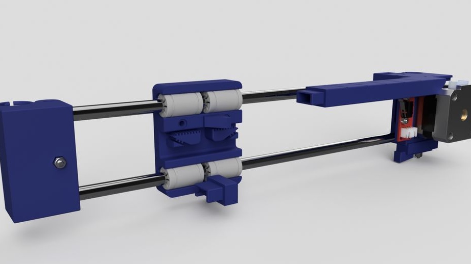
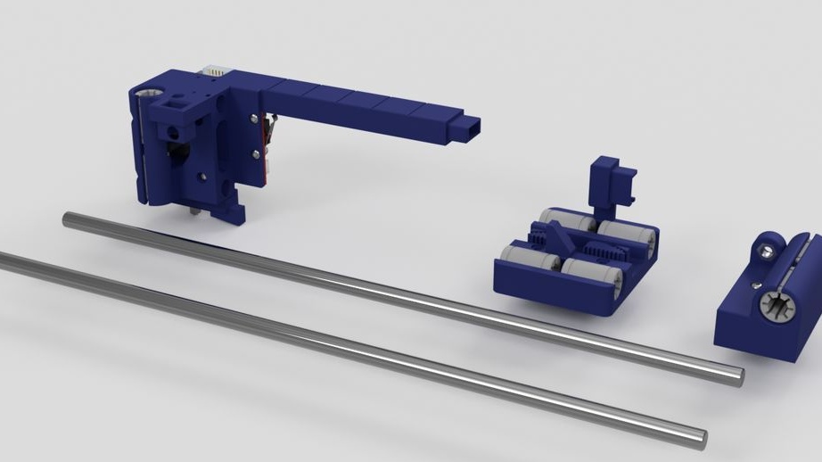
Adds rods.
- two rods 8 mm * 335 mm;
- engine mount;
Installs the X-axis on the frame.
- two rods 8 mm * 295 mm;
- two studs M5 x 275 mm;
- two bolts with nuts M4 x 8 mm;
- printed part No. 47;
- printed part No. 48;
The ends of metal rods, for better fixation, the master skins. After installing the X-axis sets the timing belt.
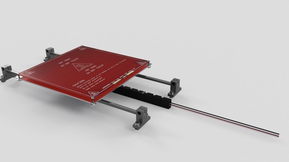
Step sixteen: printing table
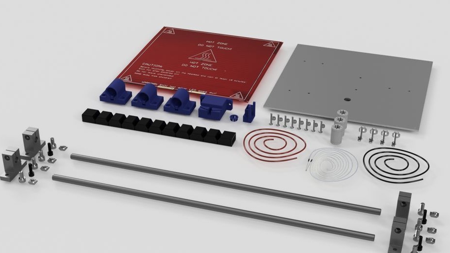
The following details are required for the printing table:
- two metal rods 8 mm * 400 mm;
-1 m. 2.5 mm stranded wire with black insulation;
-1m. 2.5 mm stranded wire with red insulation;
- three bearings LMU88;
- aluminum plate 220 mm x 220 mm x 2.5 mm;
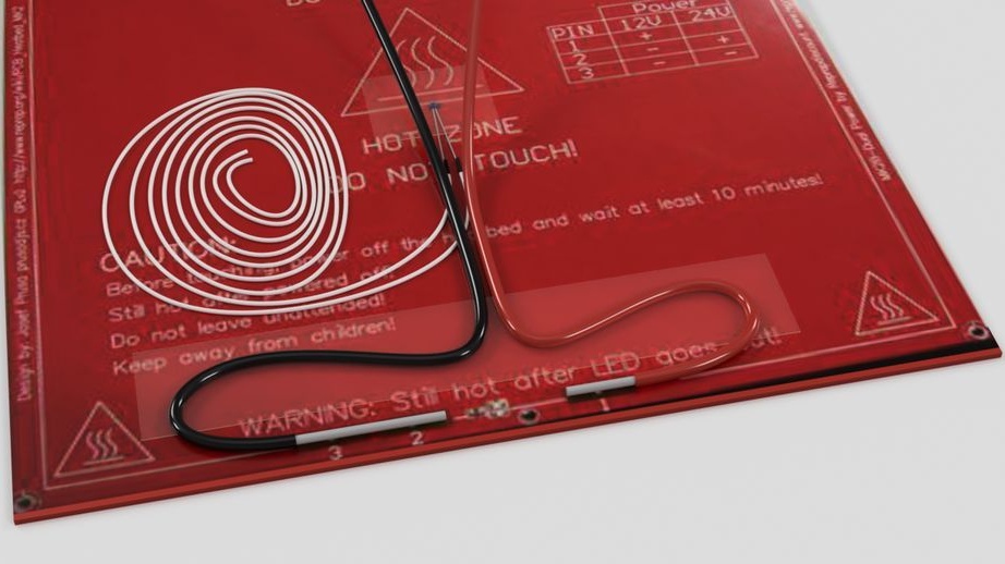
- Heated table MK2B 12 / 24V;
- thermistor;
- printed part No. 23;
- printed part No. 24 - 3 pcs;
- printed part No. 25;
- printed part No. 26;
- printed part No. 51;
- Fasteners;
When printing a part, it is necessary to heat its lower layer. A special table heater copes with this task. A thermistor is attached to the bottom of the heater. The heater itself is attached to an aluminum plate.
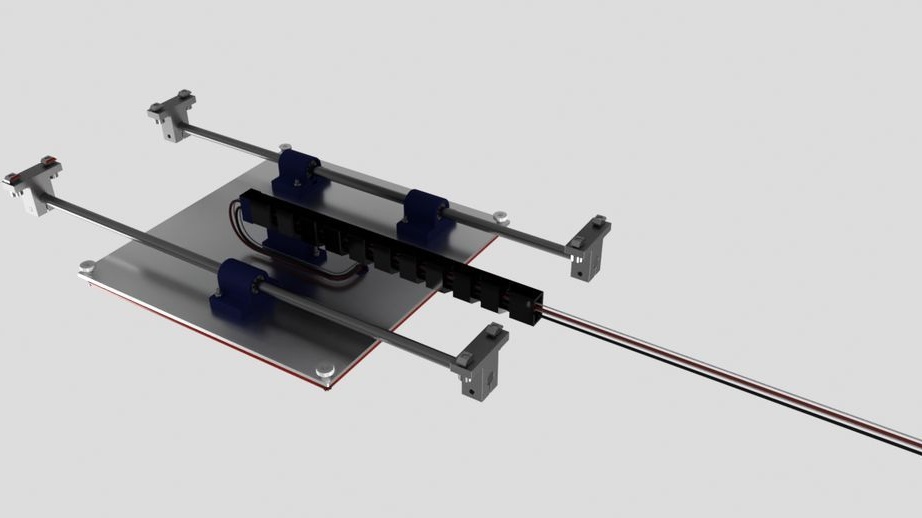
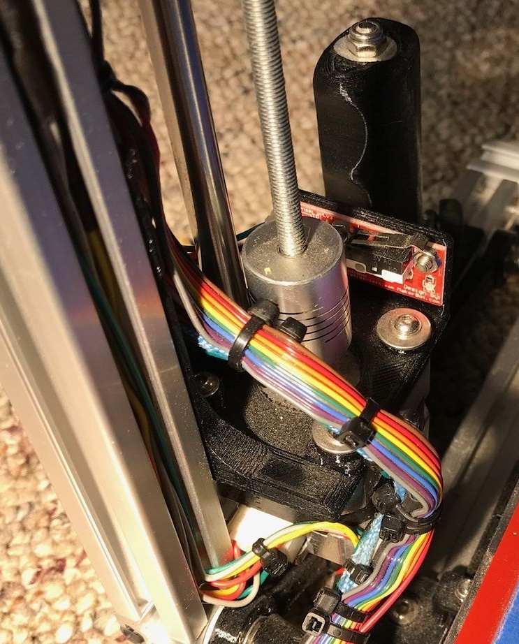
Step Seventeen: Y-axis
Assembles engine mount.

- 20 toothed MT2 pulley with screws;
- NEMA17 stepper motor;
-motor mount;
- fasteners;
Knot wire pull.
- bearings;
- printed part No. 28;
- printed part No. 29;
- fasteners;
Limit switch assembly.

- limit switch;
- printed part No. 27;
- fasteners;
Sets the printing table in its place. Connects a wire. Establish a gear belt.


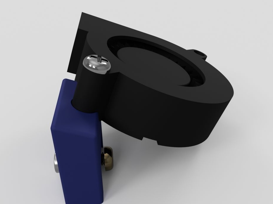
Step eighteen: fan
Assembles a blower assembly.

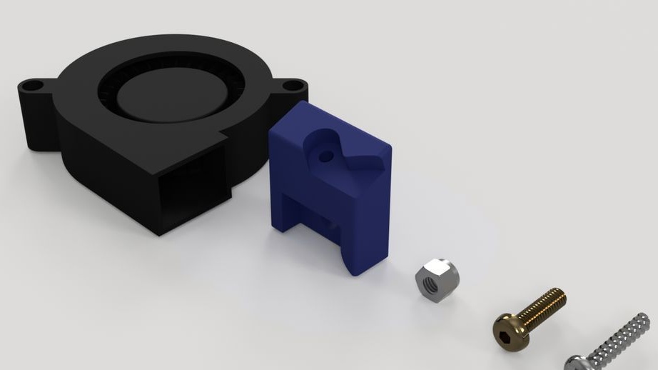
- printed part No. 18;
- 12V fan;
- fasteners;
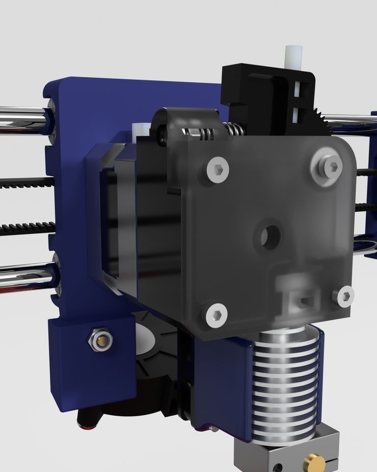
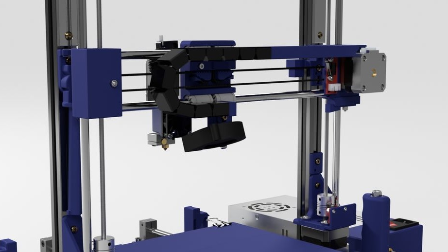
Step nineteen: printhead
The entire assembly process of the head assembly is shown in the photographs. During installation, follow the manufacturer's instructions.
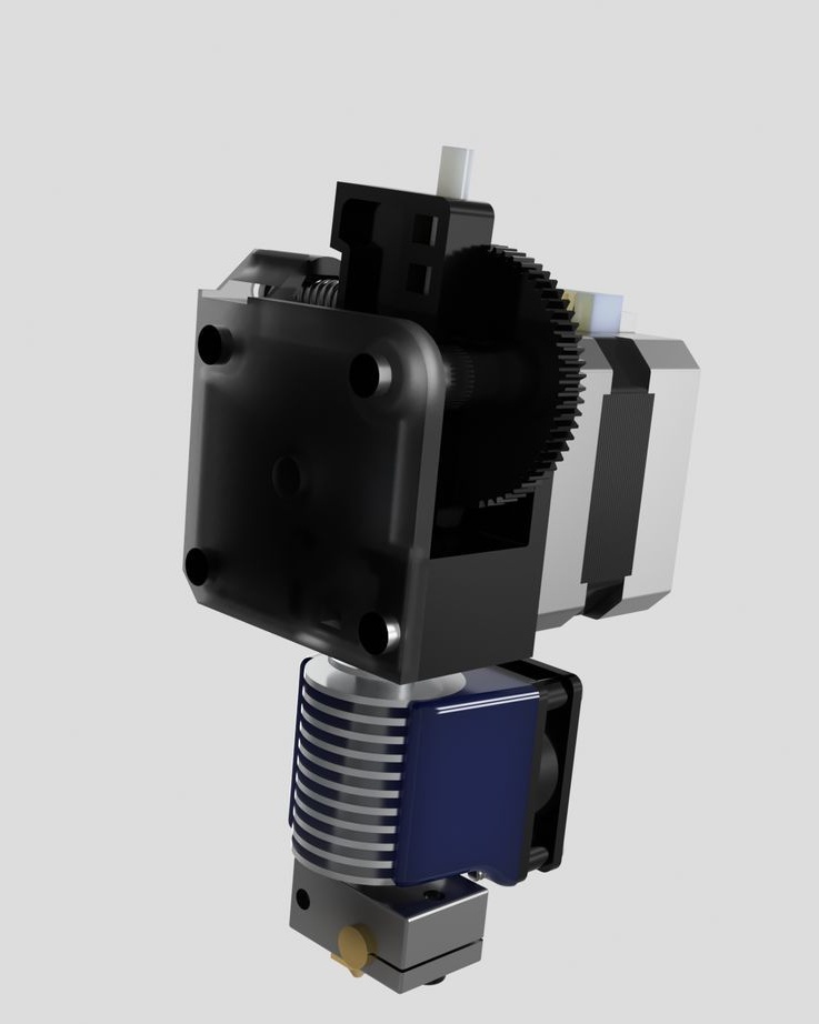
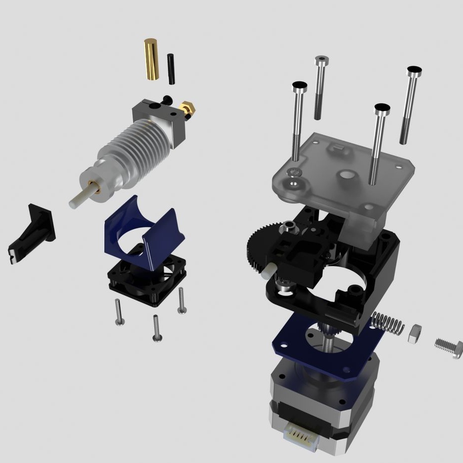
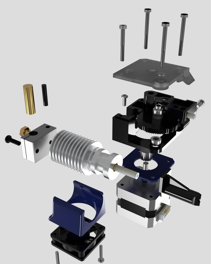
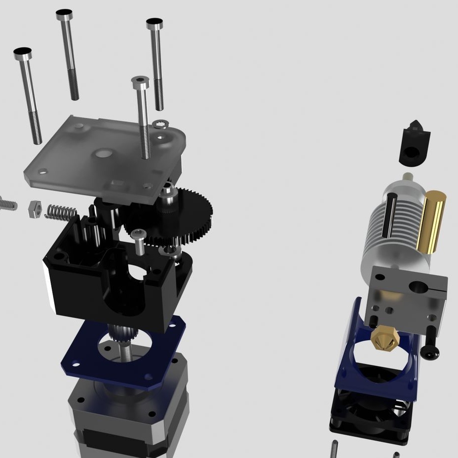
- extruder E3D Titan;
- head E3D V6;
- NEMA17 stepper motor;
- printed part No. 53;
Installs the head and blower on the printer.

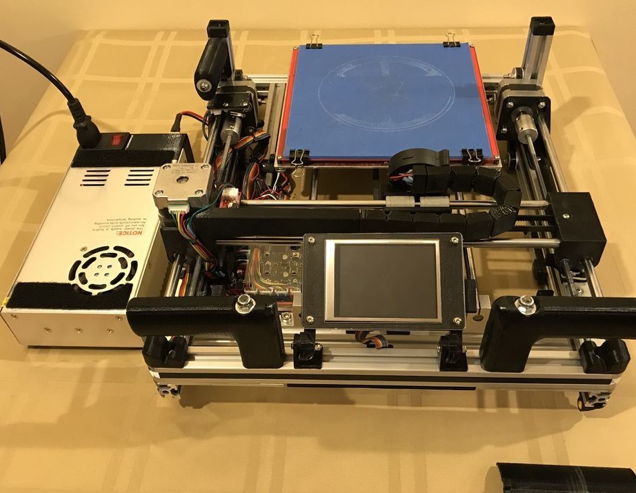
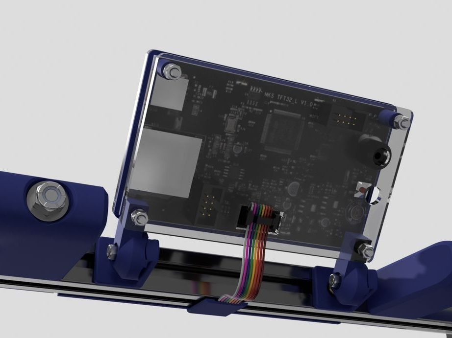
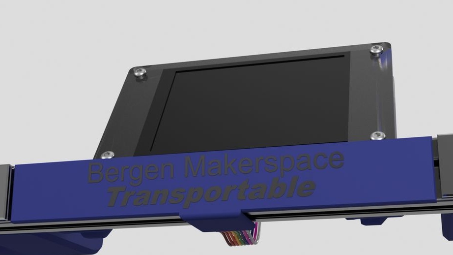
Step Twenty: Touch Panel
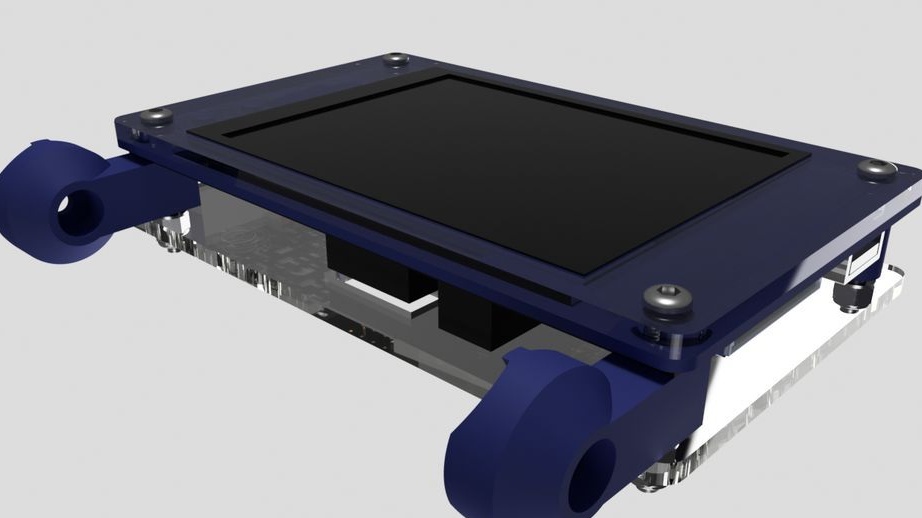
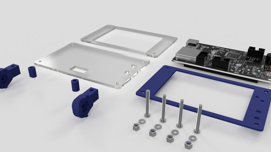
- touchpad MKS TFT32;
- front part of the touch panel (laser cutting);
- back holder of acrylic (laser cutting);
- printed part No. 22;
- printed part No. 19 - 2 pcs;
- printed part No. 21;
Trim the excess contacts on the back of the speaker buttons. Installs and combines part number 22. Installs acrylic.
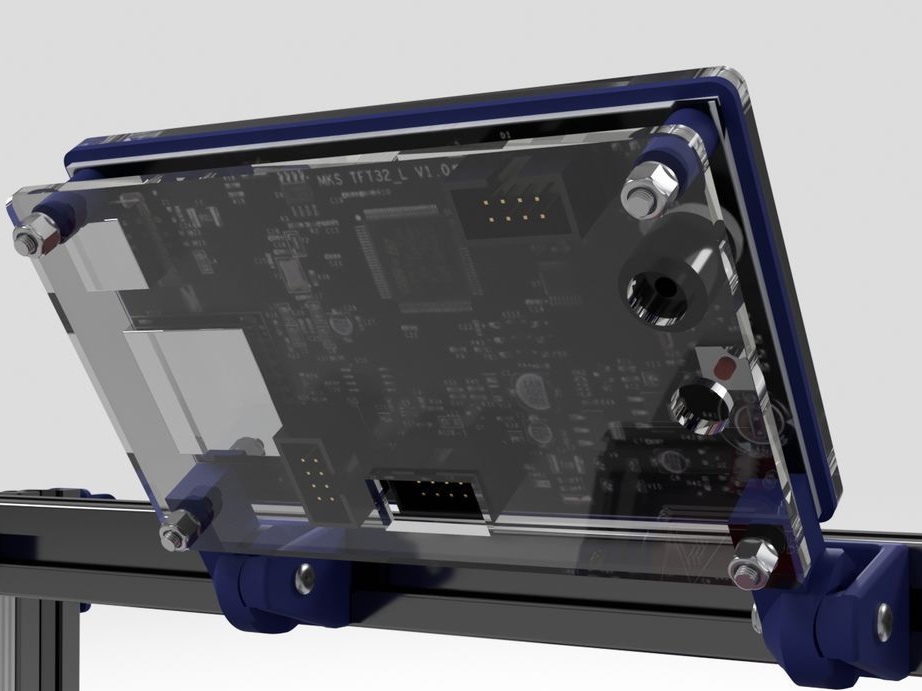
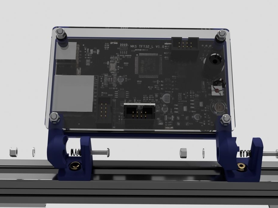

Next, install the touch panel on the printer. for this he needed fasteners, two springs and a printed part No. 20.
Step twenty-first: pens
Assembles and installs handles.
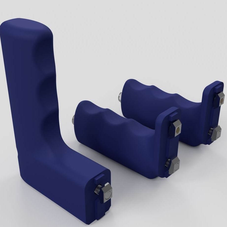
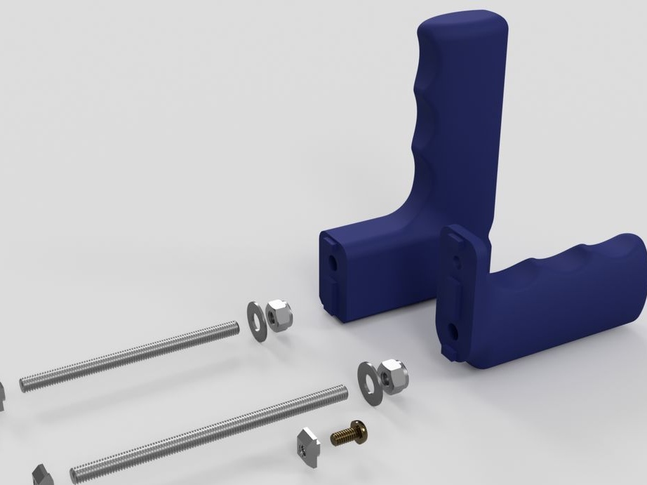

- printed part No. 54;
- printed part No. 55 - 2 pcs;
- fasteners;
Step twenty two: glass
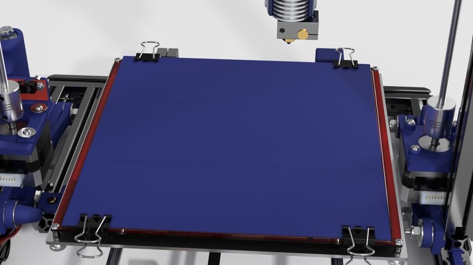
Installs a borosilicate glass plate on the table. Covers the plate with a blue cloth.
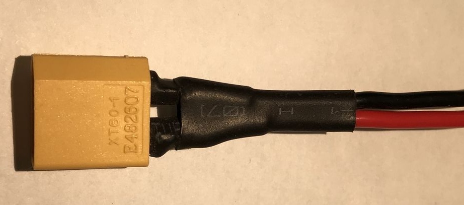
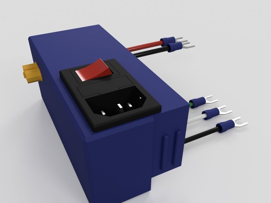
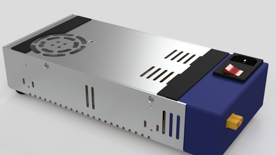
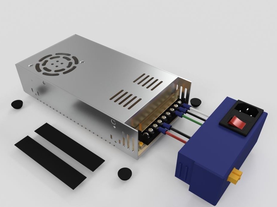
Step twenty three: power supply
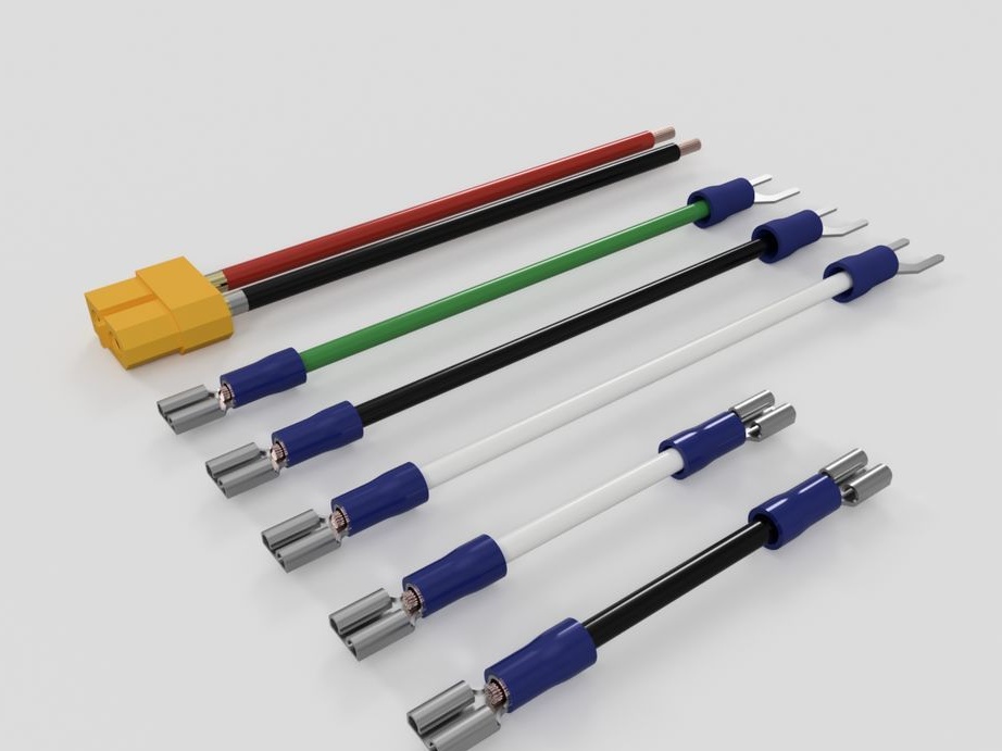
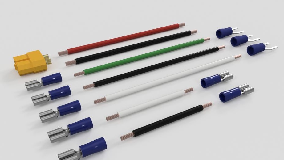
For power supply, the master uses a stranded copper wire with a cross section of 2.5 - 3 mm, connectors, terminals.
Installs wires on the power connector.
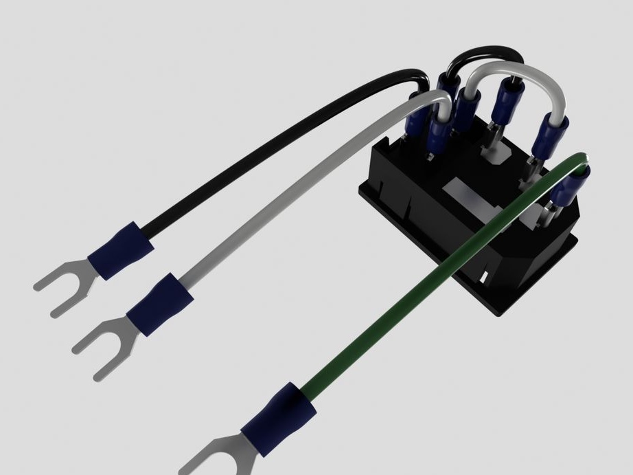
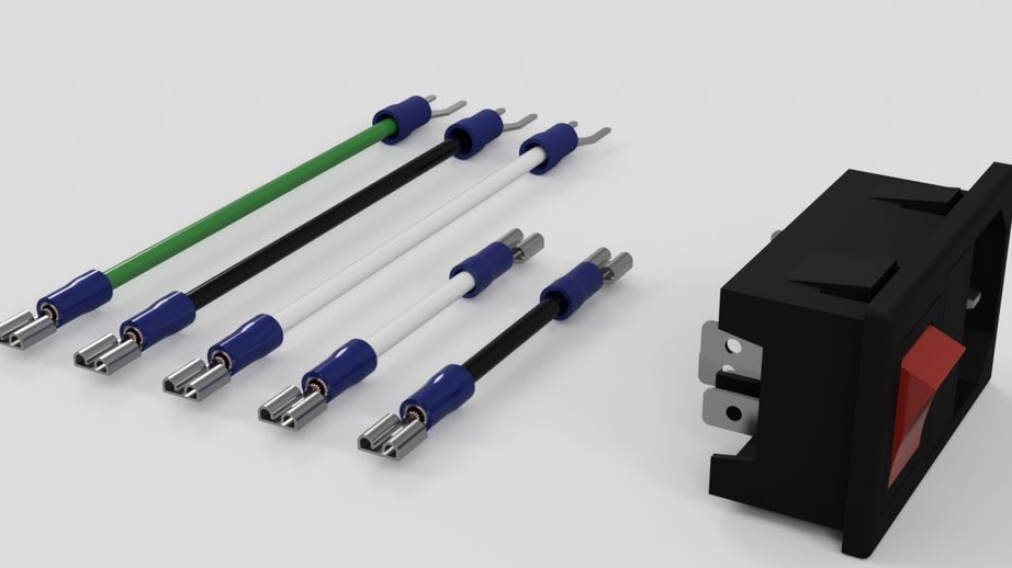
Installs the connector on printed part No. 57. Installs two 12V wires.
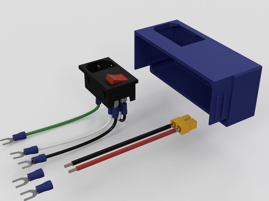
Connects to a regulated power supply 12V DC 30A 360W. Installs rubber feet on the PSU.
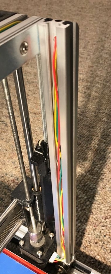
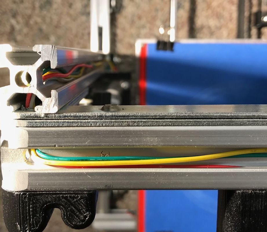
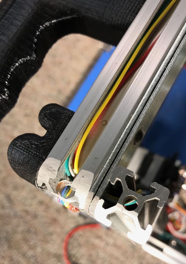
Connects the electrical parts of the printer. Wires are laid and secured in the profile.
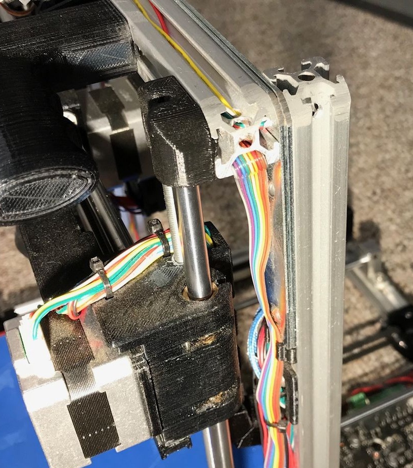
Connects a controller.
Covers the top of the controller with acrylic.
Video on wiring.
Step Twenty-Four: Coil
Collects a coil.
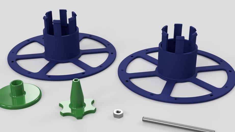
- printed part No. 63;
- printed part No. 62;
- printed part number 64;
Step twenty fifth: case
The case needs to be finalized and the mounts installed inside it.
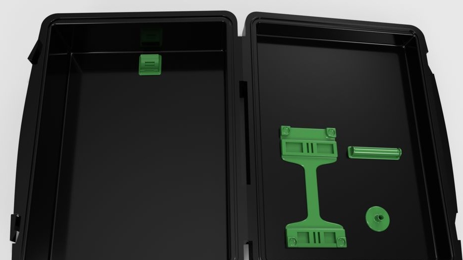
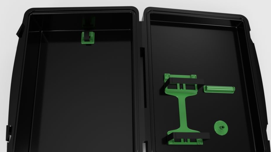
- printed part No. 59;
- printed part No. 61;
- printed part No. 62;
- printed part No. 58;
- Velcro
Step twenty-six: firmware
The firmware used on the MKS BASE controller is Marlin. This is an open source project, and MKS is the right version available on the page. New versions are posted on this page periodically, and the package described here will be the same as the “firmware (marlin & TFT) .zip”, which contains the Marlin firmware version 1.1.6 and the firmware for the TFT32 touch panel. Select this option and click the Download button. The following instructions assume that you are using a PC running Windows 10 to process packages, but equivalent operations are available on a Mac.
Create an empty directory to store the firmware. Unzip the zip file, then unzip the Marlin package inside it.
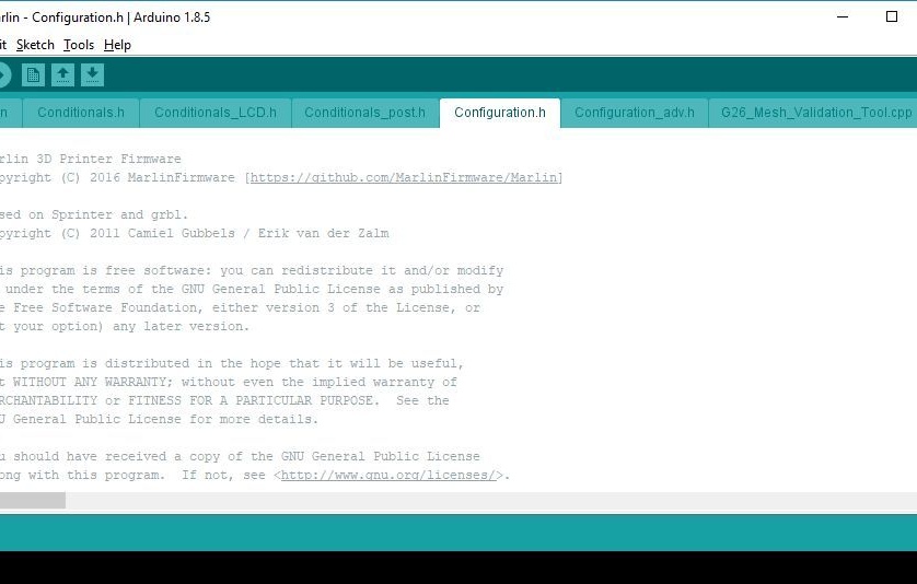
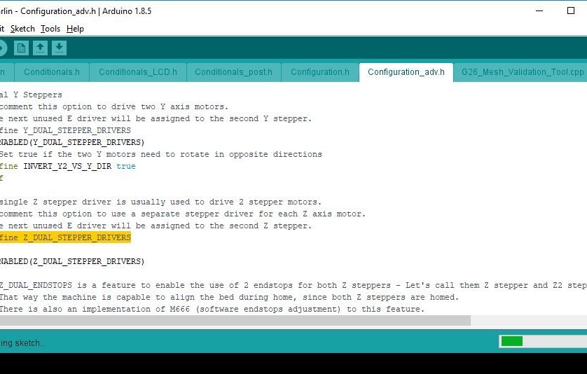
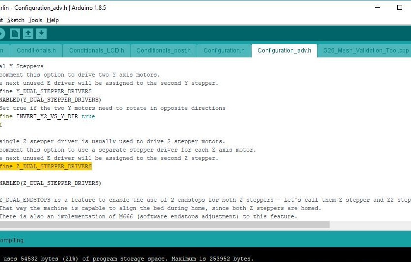
Download and install IDE Arduino from . Launch the IDE and use File> Open to select the Configuration.h file from the Marlin package directory. Now make sure that the package can be compiled by clicking the "Check" button. After several minutes of processing, a message about successful compilation should appear at the bottom of the screen.
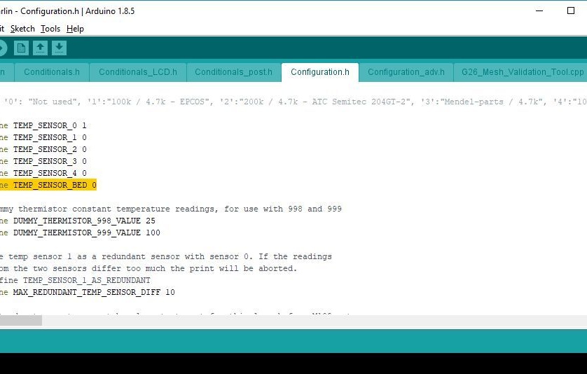
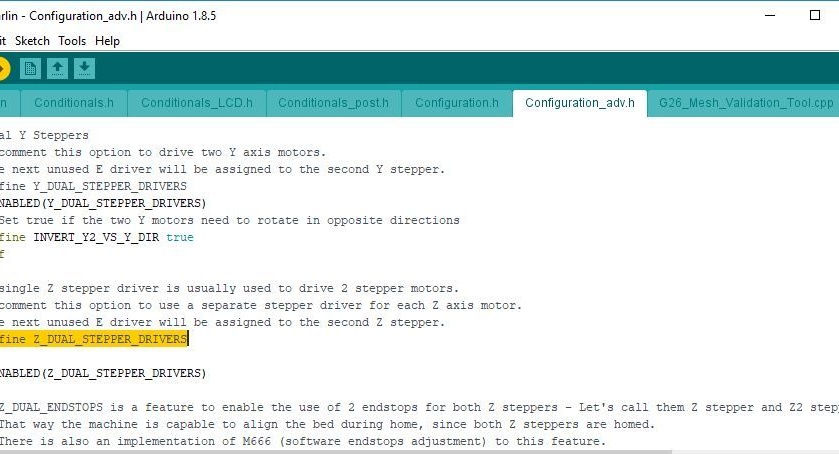
Select the tab containing the Configuration.h file. Check and edit the text:
#define TEMP_SENSOR_BED 1
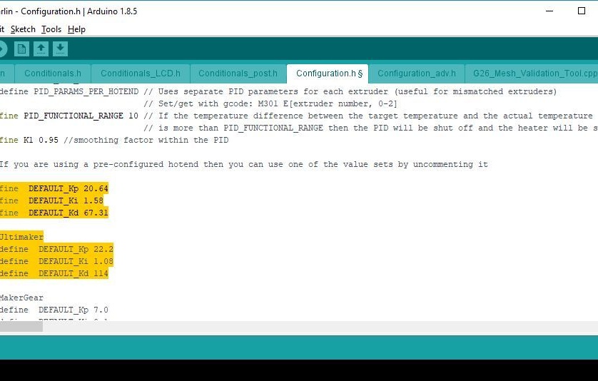
#define DEFAULT_Kp 20.64
#define DEFAULT_Ki 1.58
#define DEFAULT_Kd 67.31
#define X_MIN_ENDSTOP_INVERTING true
#define Y_MIN_ENDSTOP_INVERTING true
#define Z_MIN_ENDSTOP_INVERTING true
#define INVERT_X_DIR true
#define INVERT_Y_DIR false
#define INVERT_Z_DIR true
#define INVERT_E0_DIR true
#define X_BED_SIZE 200
#define Y_BED_SIZE 200
#define Z_MAX_POS 185
#define DEFAULT_AXIS_STEPS_PER_UNIT {80,80,4000,400}
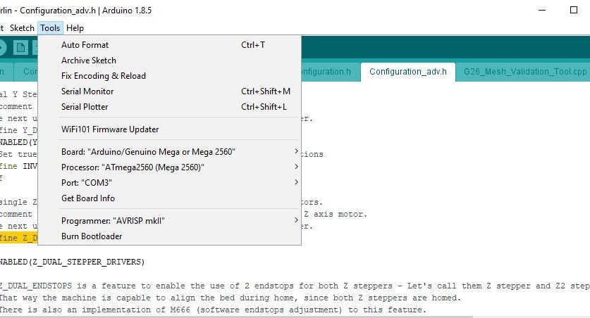
#define DEFAULT_MAX_FEEDRATE {500, 500, 3, 25}Without turning on the printer, use a suitable USB cable to connect the PC to the MKS BASE controller. Select the Tools menu in the Arduino IDE and verify that the board and processor are displayed as shown in one of the images. The port should show the USB port that is used to connect to the controller. Now click the “Download” button.
Step twenty-seven: testing the controller
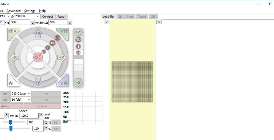

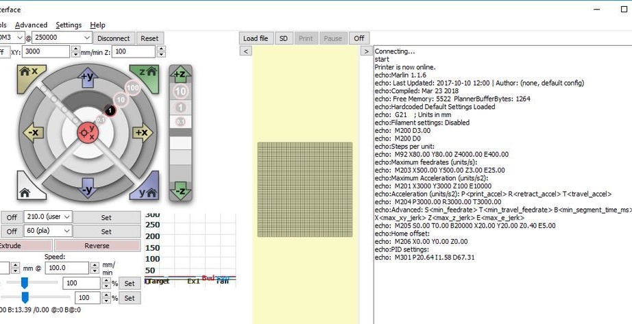
Download and install the Pronrface Printrun package at:.
Before starting the test, manually move the print unit and print head to the center. Use a ruler for proper positioning.
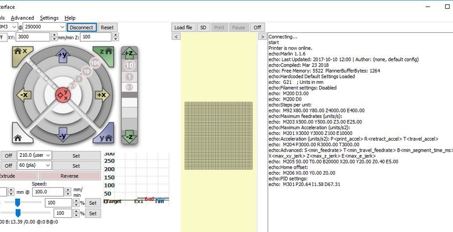
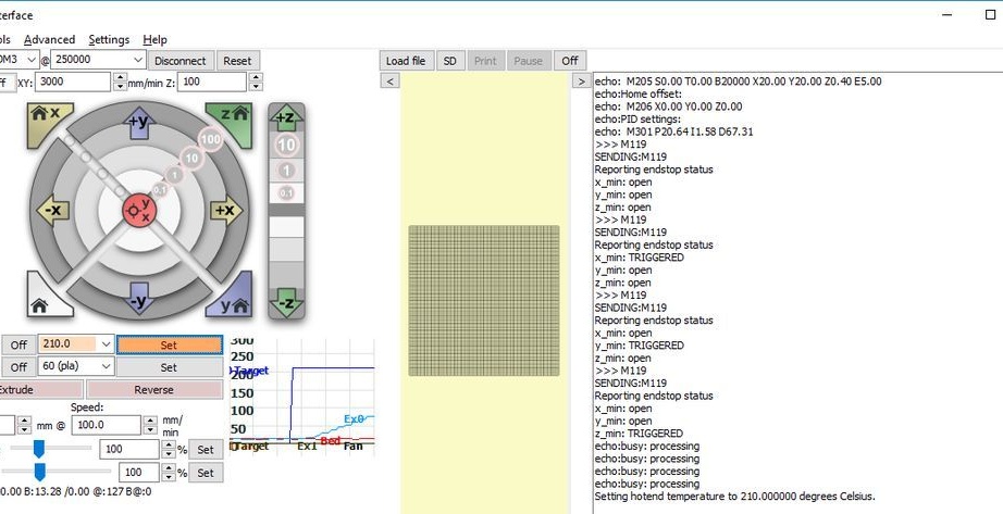
In the lower right corner of the window, enter “M119” and click on the “Submit” button. One by one, press and hold each of the X, Y, and Z axis switches. Press Submit after each press of the switch. Each test should show the corresponding switch as TRIGGERED.
Connect the 12 V DC power supply to the printer and turn it on. Move the print head up 1 mm by clicking the “1” button inside, which is located in the Z movement section of the screen. Make sure that both Z motors move in unison and the print head rises 1 mm. You can press the button several times to confirm.
Repeat the same test with the X and Y engines using their on-screen controls. The print head should move to the right, and the printed circuit board should move toward the front of the printer.
Manually adjust nodes with limit switches.
Press the X home button and make sure the X carriage moves to the left end and stops. Perform a similar test using the Y home and Z home buttons.
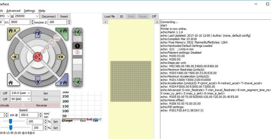
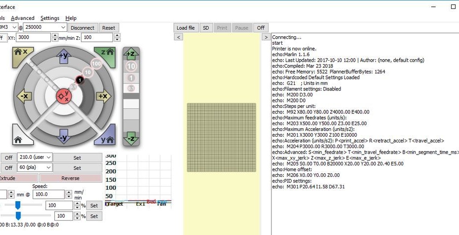
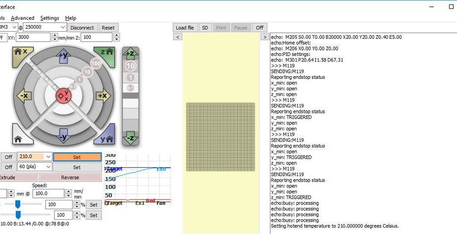
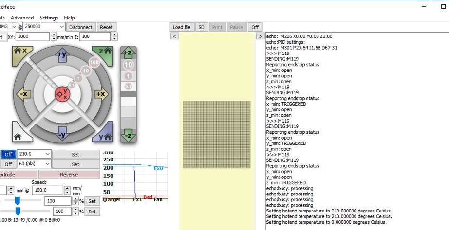
In the window section with the inscription "Heat" enter 210 ° С. In the lower left window after T, the current nozzle temperature is indicated. Click Set. The nozzle should start to heat up, and the chart to the right of the button will show that the nozzle temperature is rising.
These are the settings of the E3D extruder. When installing another part, other settings are possible.
Now check the table heating. It is indicated on line B.
Step twenty-eighth: touch panel firmware
Touch panel firmware requires an SD card. Firmware can be downloaded.
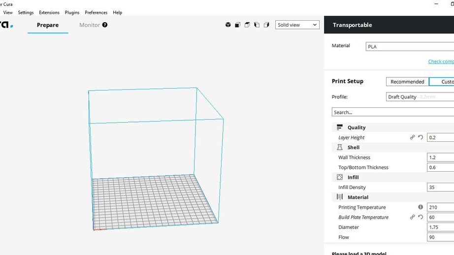
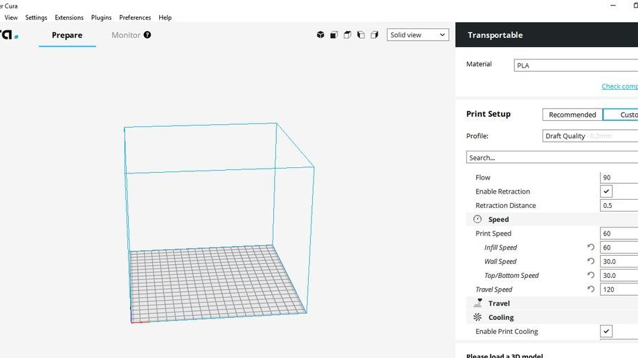
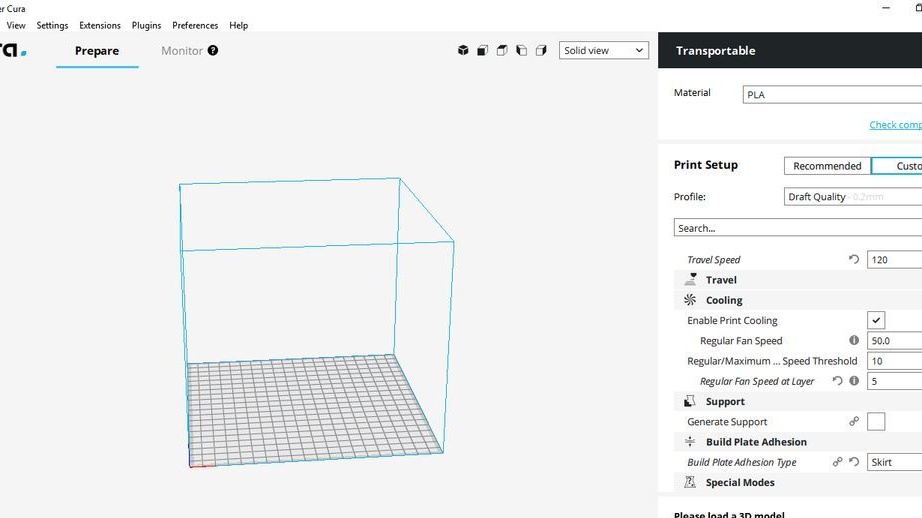
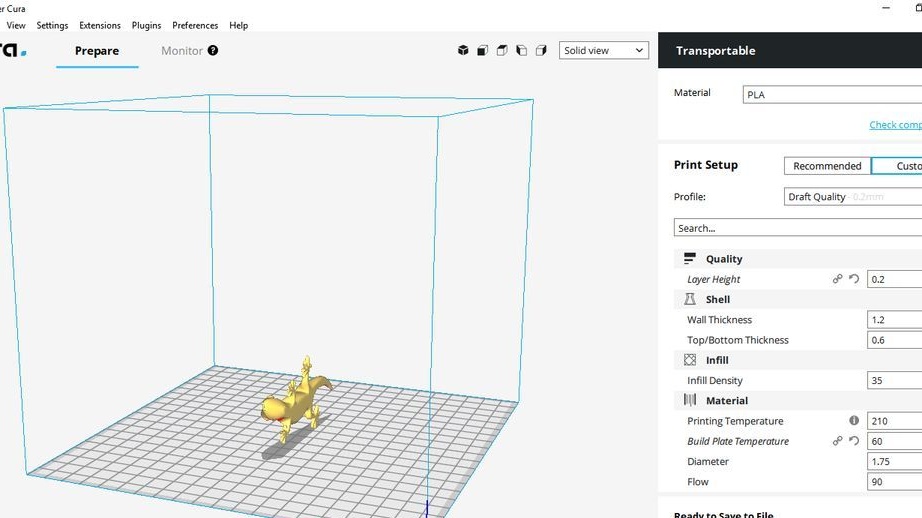
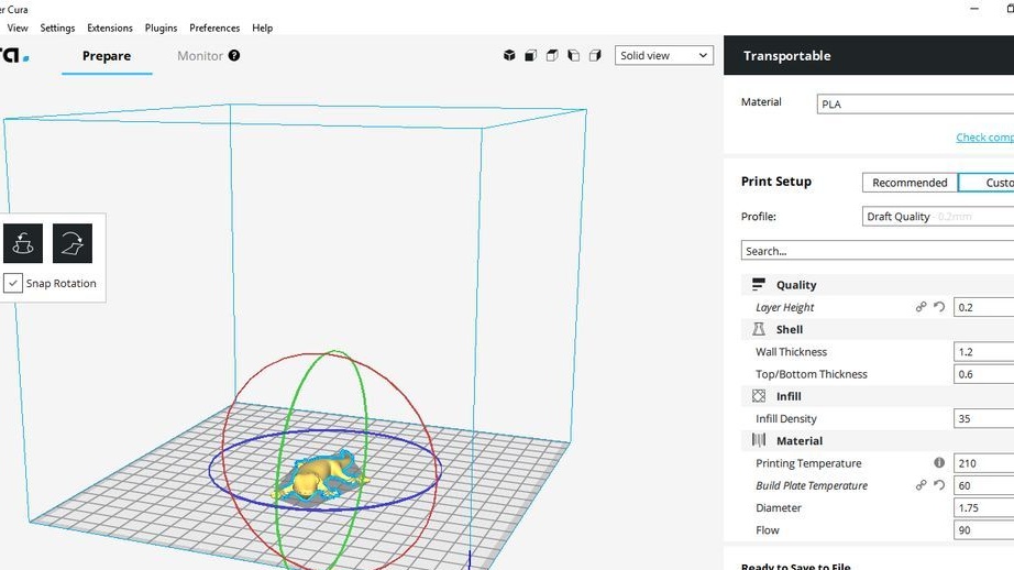
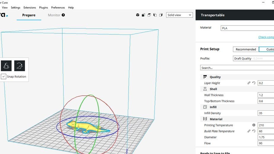
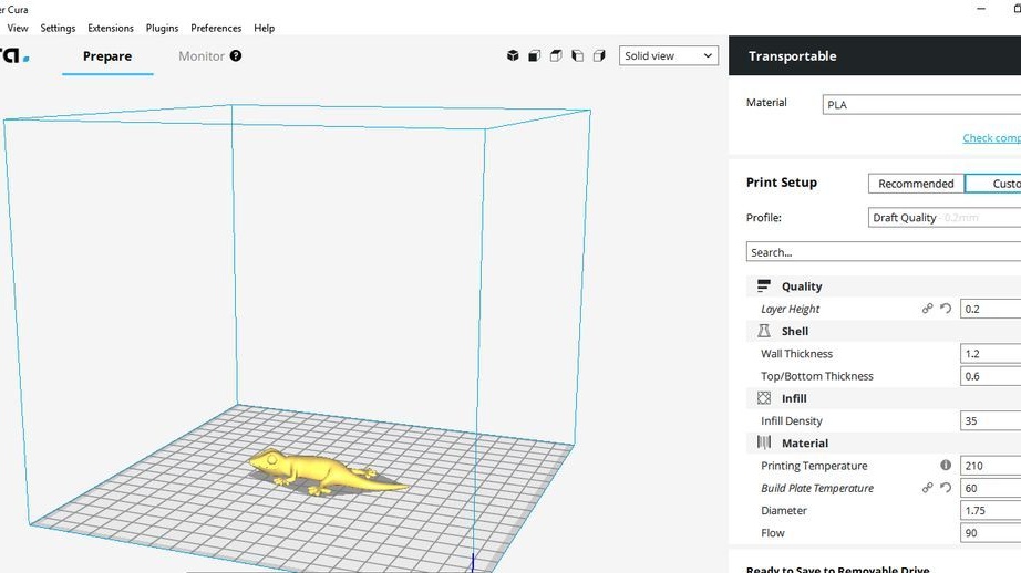
Step twenty-nine: software
For the printer to work, software must be downloaded to the computer. The wizard uses software.
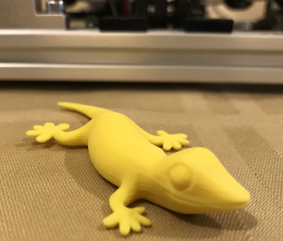
After installing and configuring the software, you can start printing.