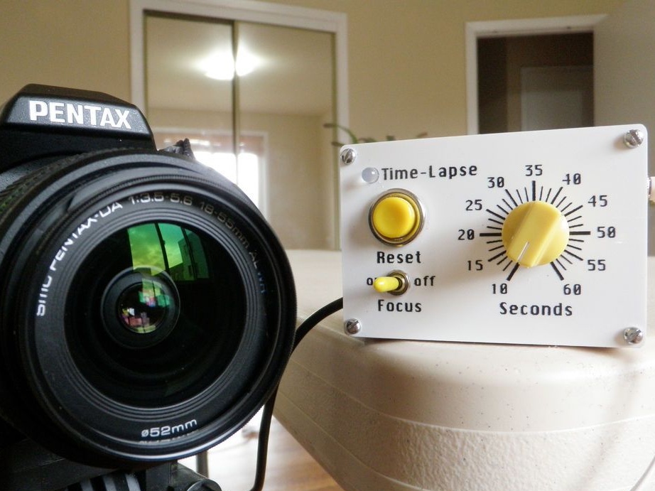
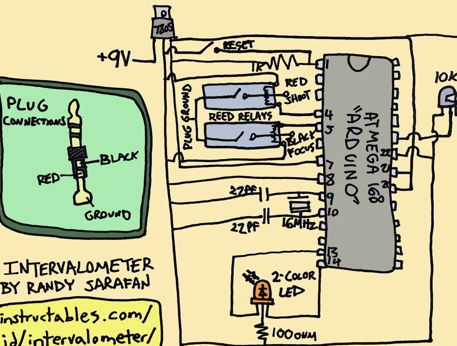
Homemadewhich we will consider in this article will be of interest primarily to photographers. Although, if you redo it a little, you can adapt it for other purposes. The wizard made a device that turns on the camera at regular intervals. In addition to triggering the camera, the device can instruct the camera to focus the image. The author has a Pentax camera, according to him, the device will work on other models of cameras that have the corresponding connector. The device works on the Arduino module. For its manufacture, the master-master needed the following
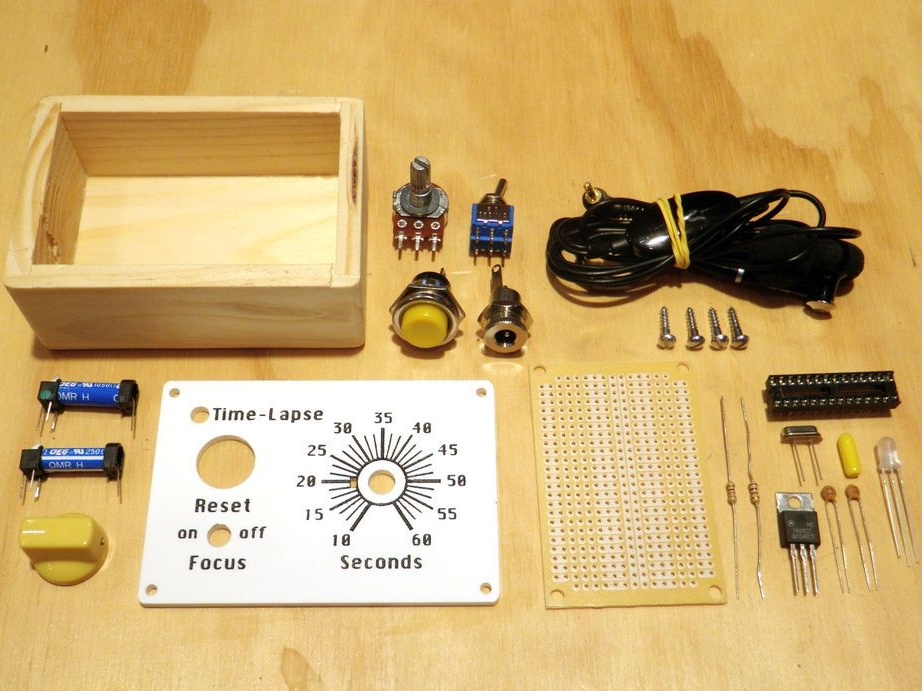
Tools and materials:
- Wooden box;
- Acrylic;
- Black acrylic paint and brush;
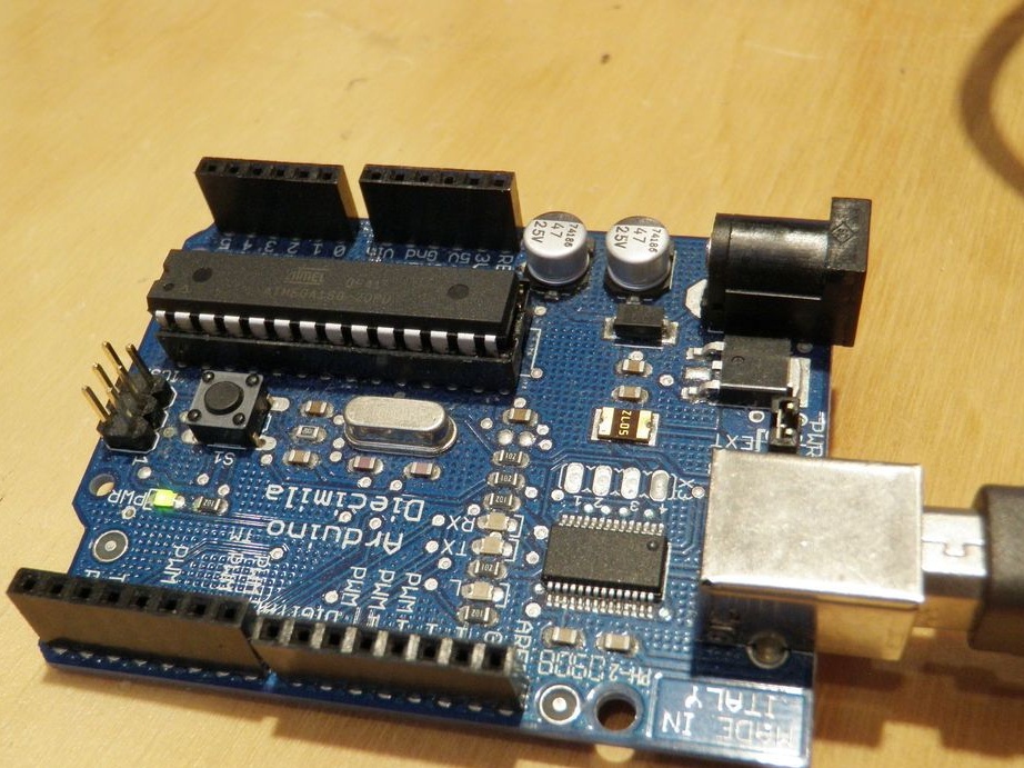
- Arduino;
- Perforated board;
- 1K resistor;
- 100 ohm resistor;
- LM7805 regulator;
- 2-color LED;
- Crystal oscillator 16MHz;
- 22pf capacitors - 2 pcs;
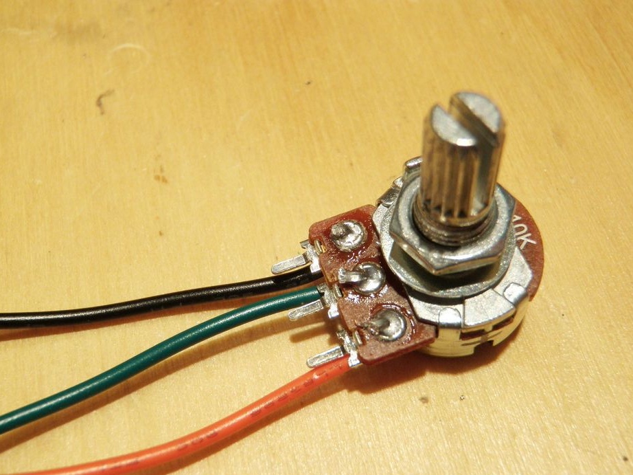
- Potentiometer 10K;
- 28-pin connector;
- DPDT toggle switch;
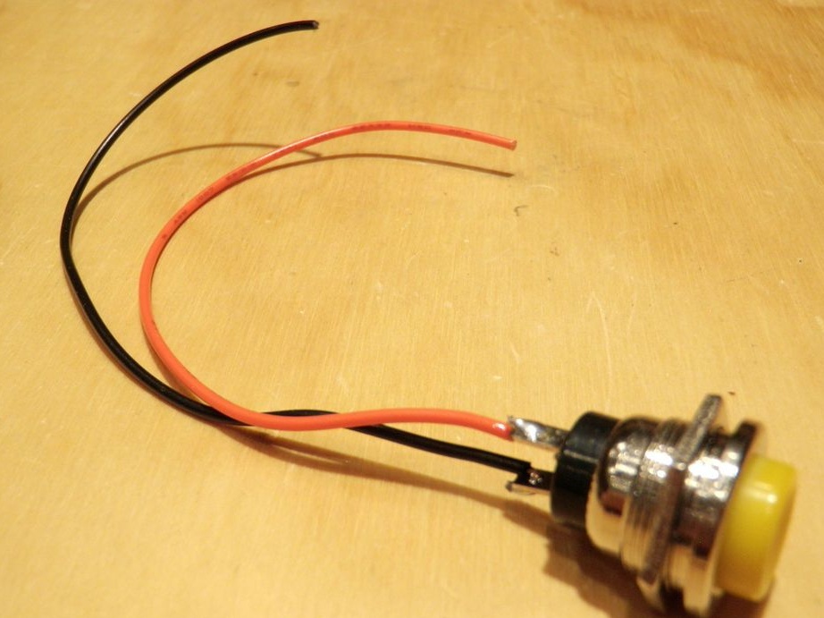
- Button switch SPST;
- Connector;
- Relay SPST 5V - 2 pcs;
- Shielded stereo wire;
- 2.5 mm plug;
- 6VDC power adapter;
- Wires;
- Fasteners;
- Soldering iron;
- Multimeter;
- drill;
- Knife;
- Nippers;
- Plotter;
- Vise;
- Insulating tape;
- 9 V battery;
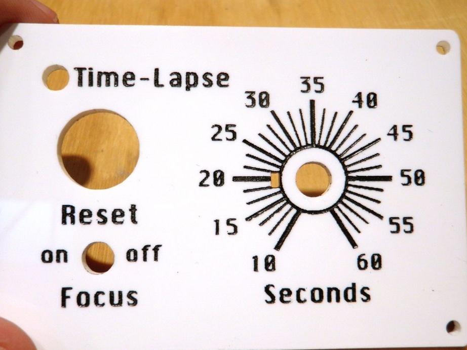
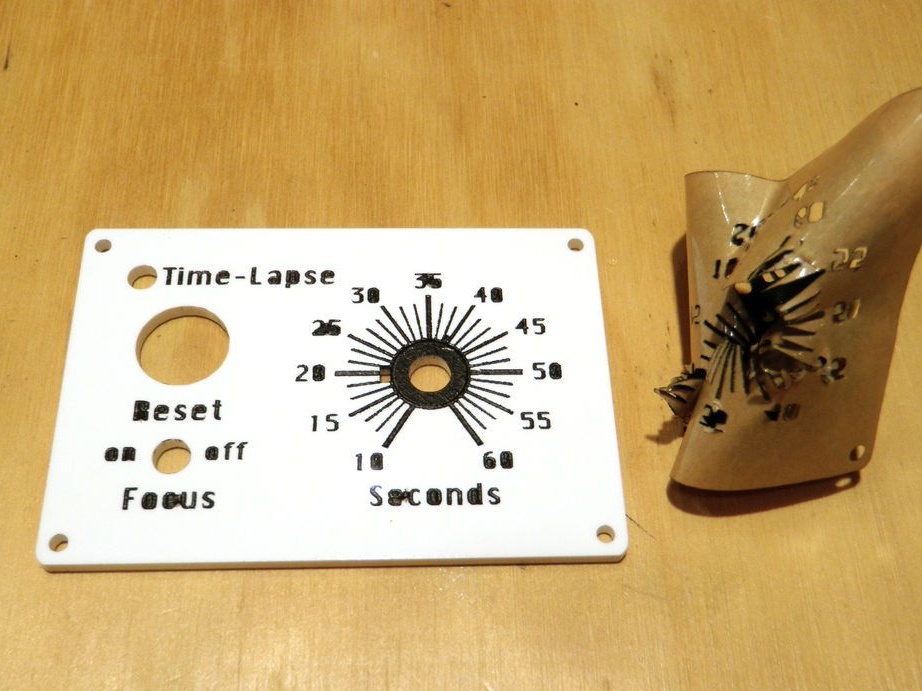
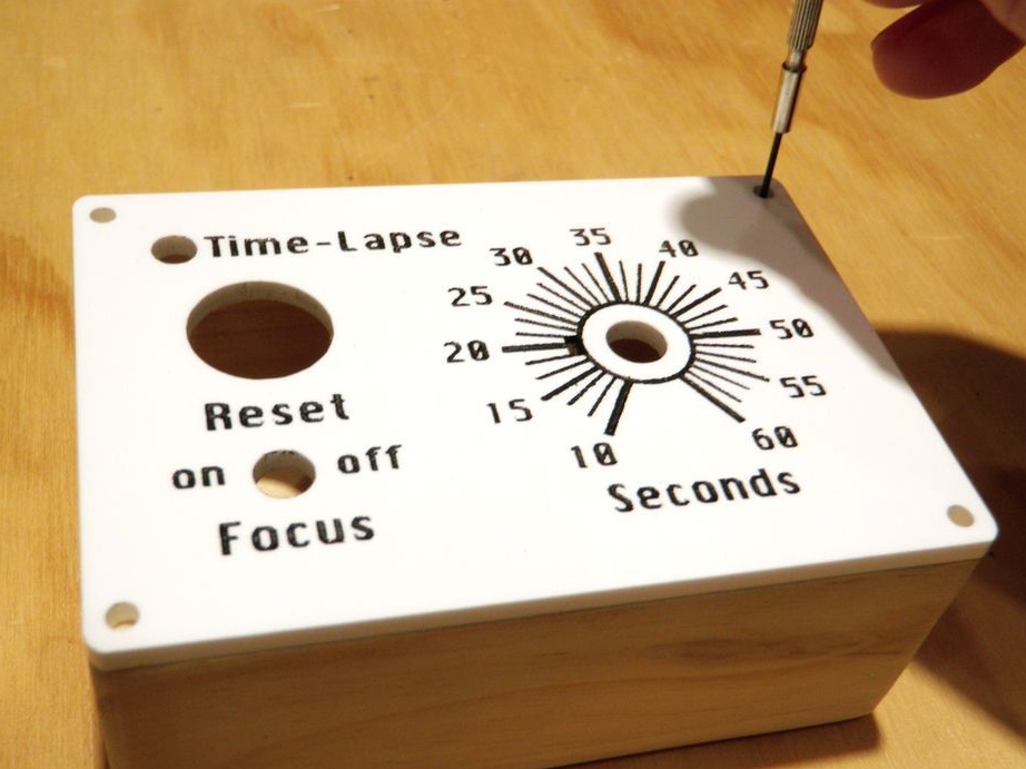
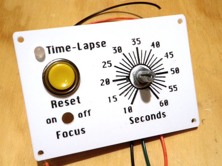
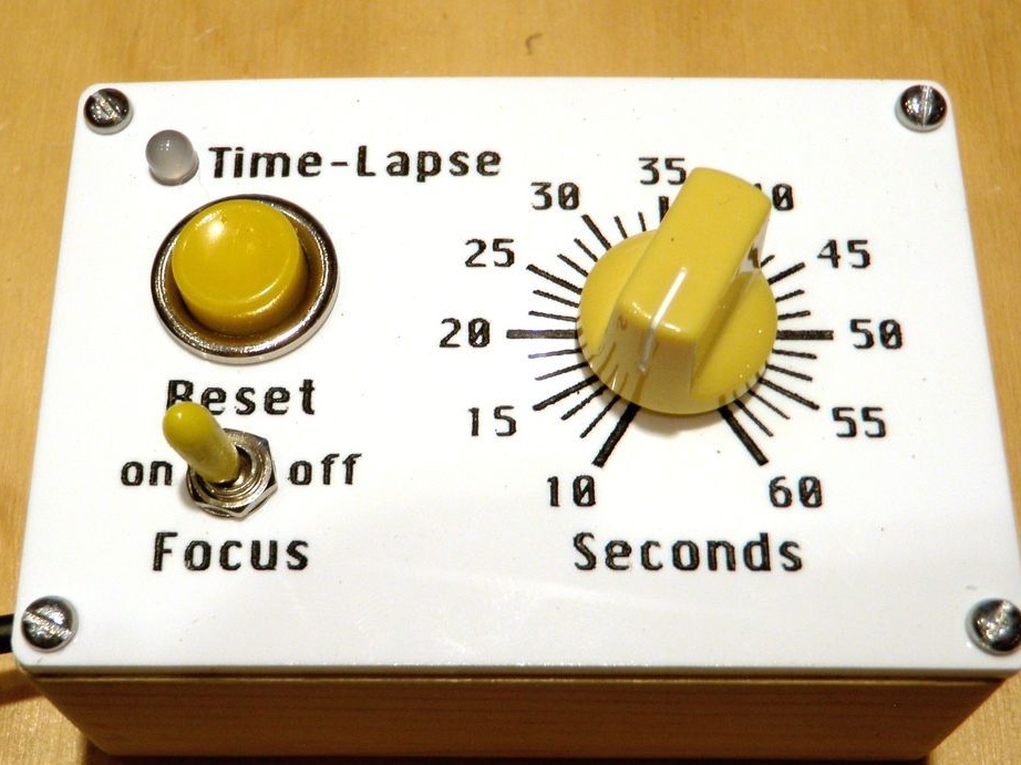
Step One: Front Panel
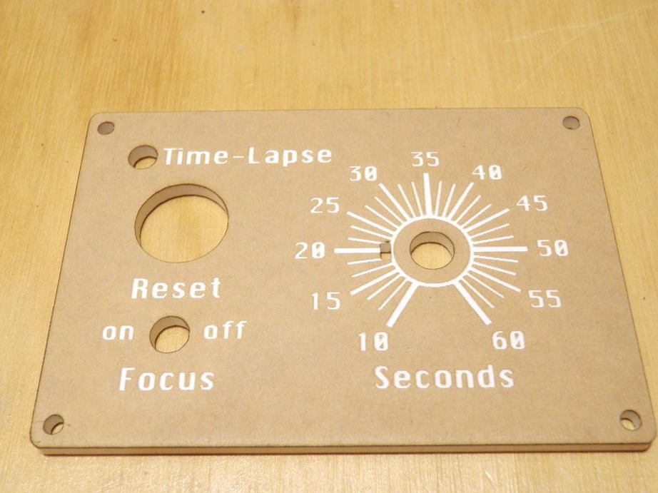
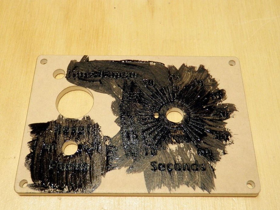
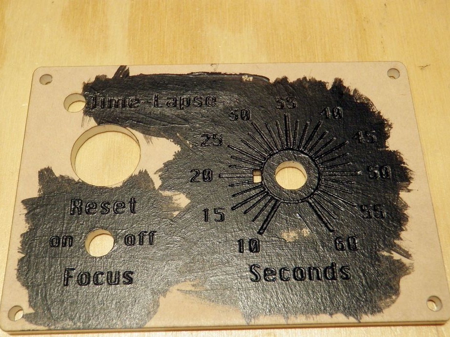
The first step is the master makes the front panel of the device. Cut acrylic to fit the top cover of a wooden box. Without removing the protective layer, cuts a template on a laser plotter. You can download the template.
Cutter Settings
Captions:
Laser path design with the following settings:
power: 70
speed: 100
frequency: 2
Holes:
power: 100
speed: 9
frequency: 5000
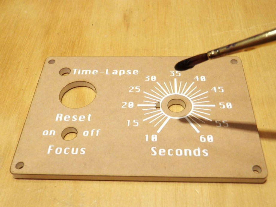
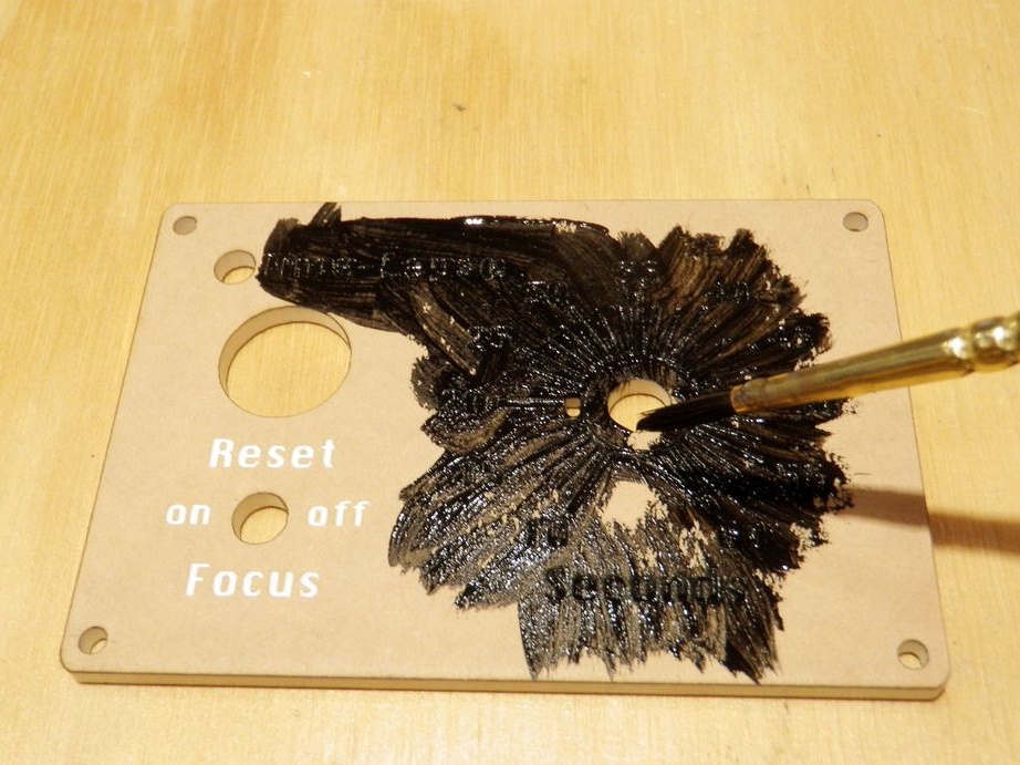
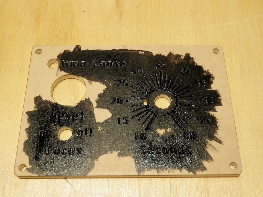
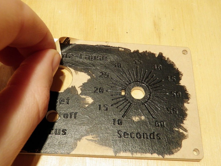
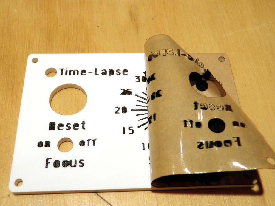
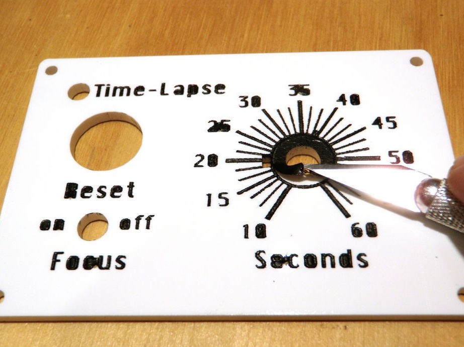
Then it puts 2-3 layers of black paint. After drying, the paint removes the protective coating.
In the absence of a cutter, you can use traditional manufacturing methods.
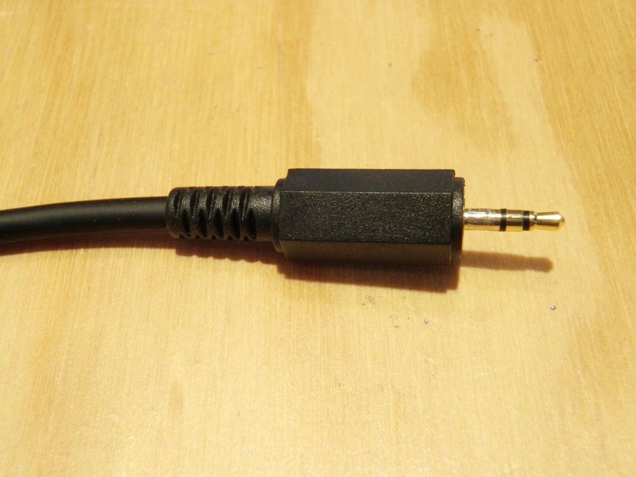
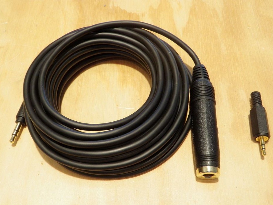
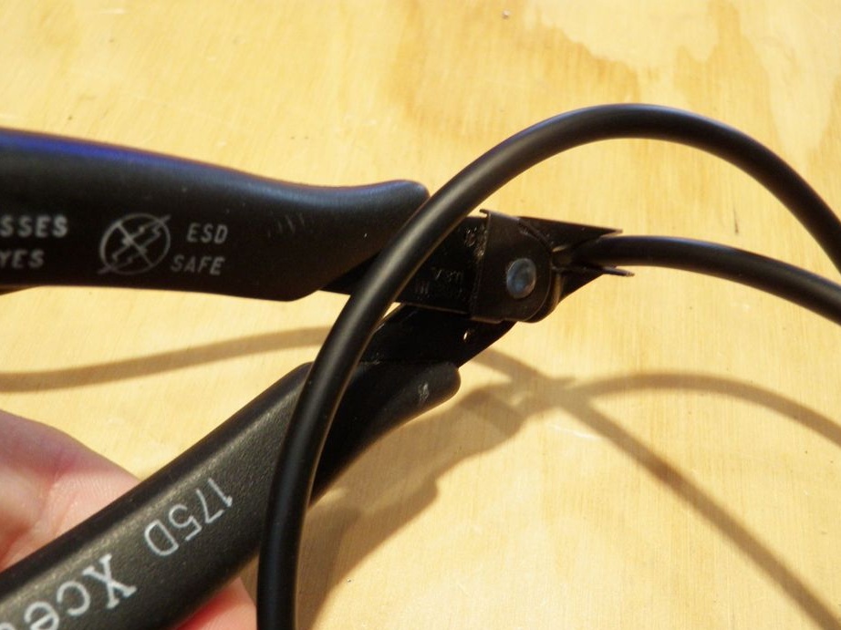
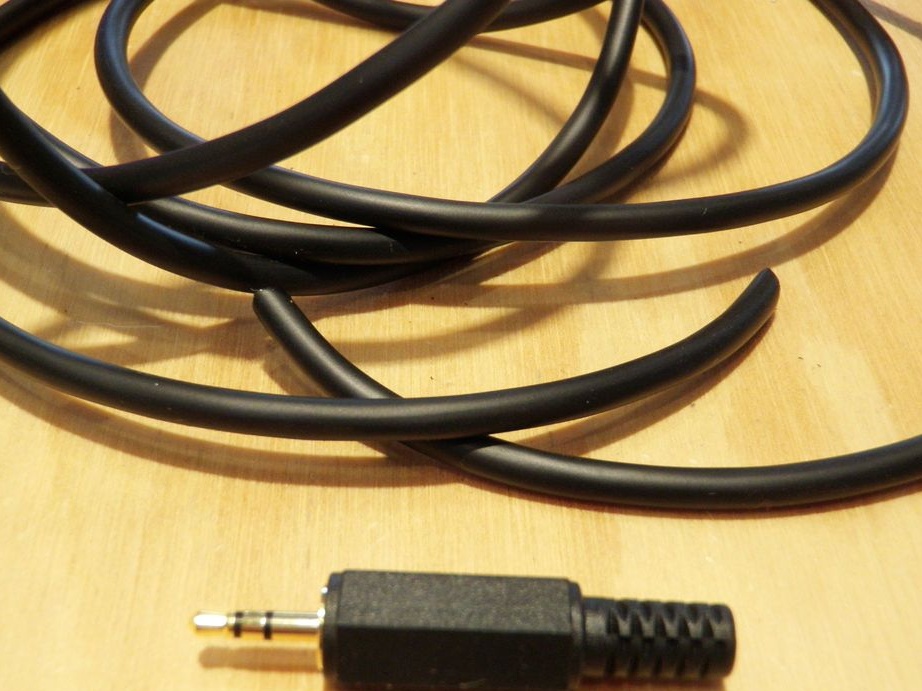
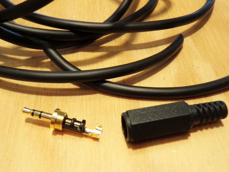
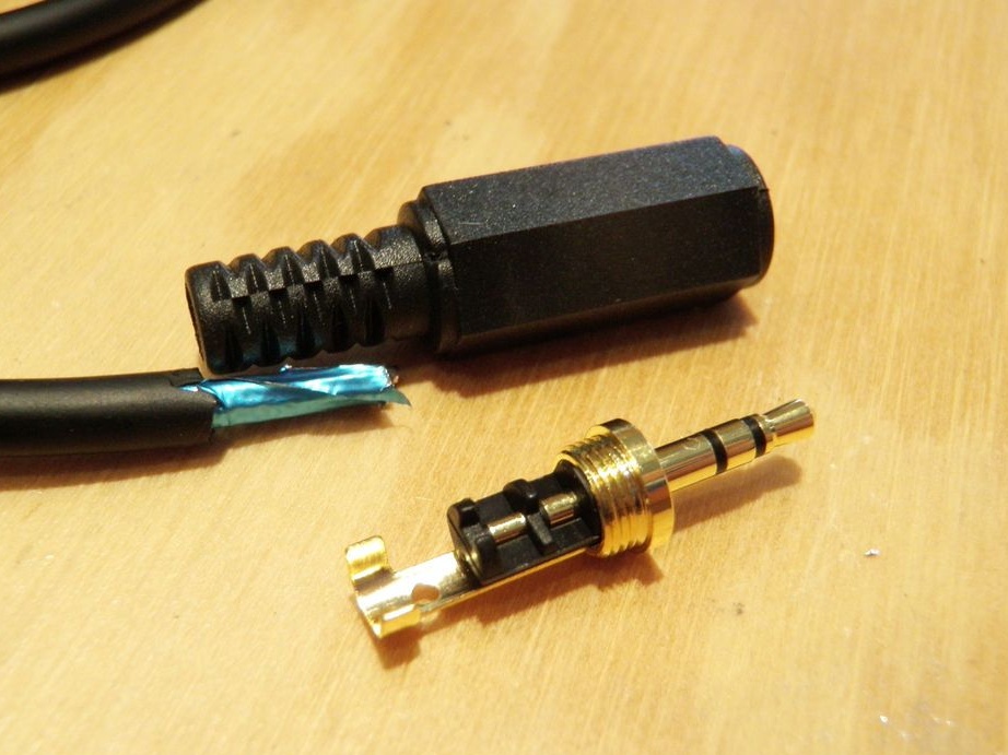
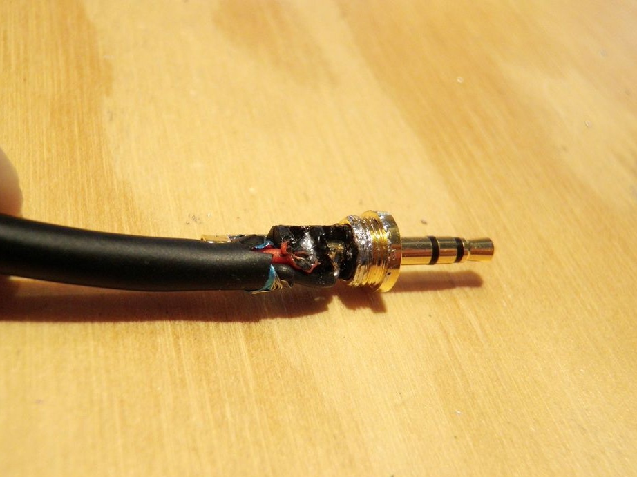
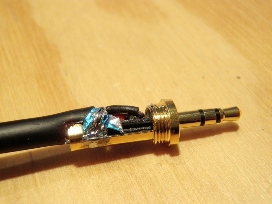
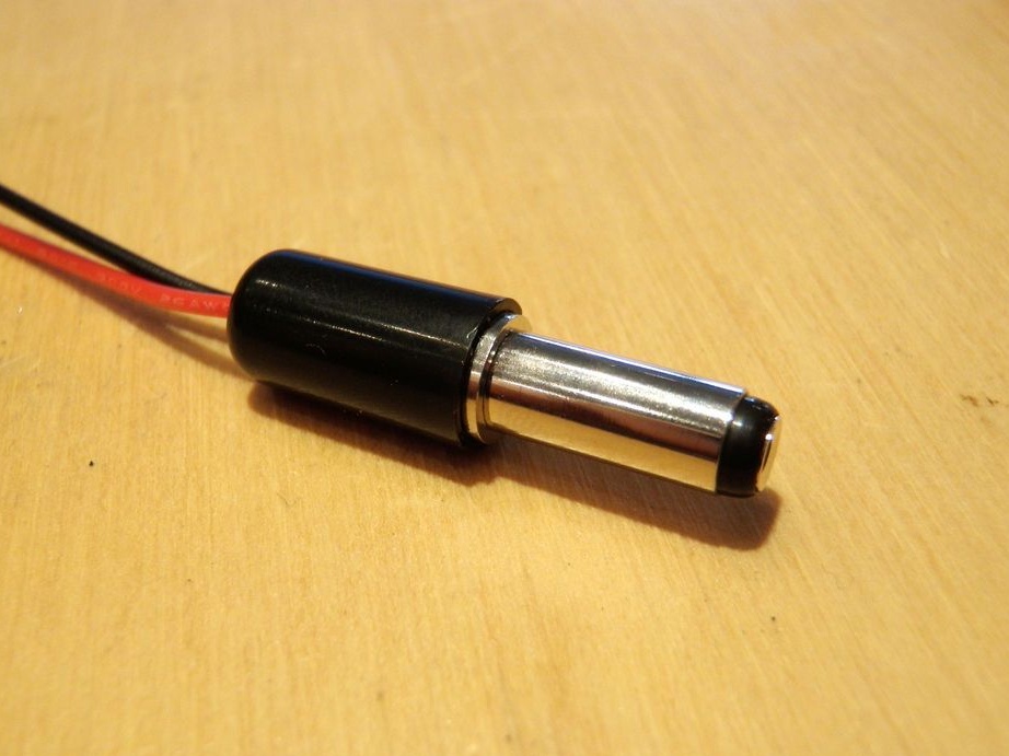
Step Two: Cable
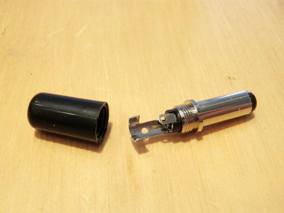
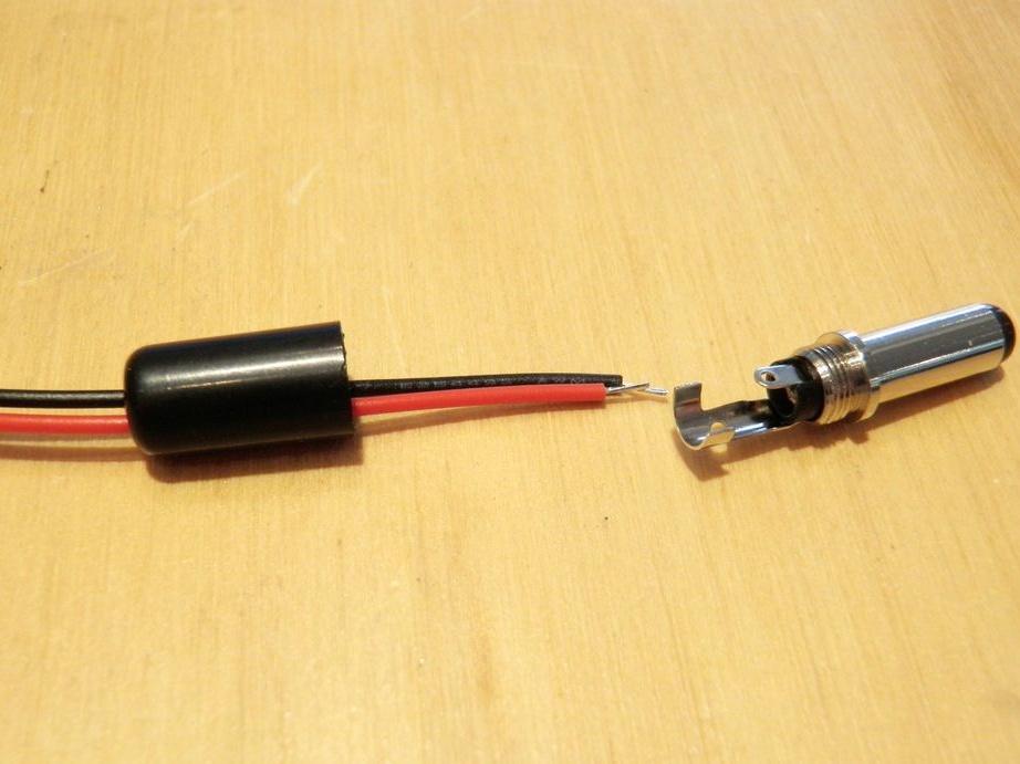
From the extension cord for headphones cuts the connector. The plug is soldered to the connector. The pinout of the wire is shown in the figure. After soldering, it checks the connections with a multimeter and installs the shell.
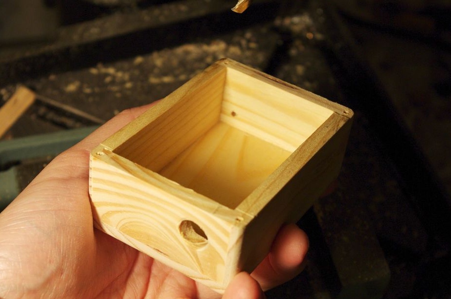
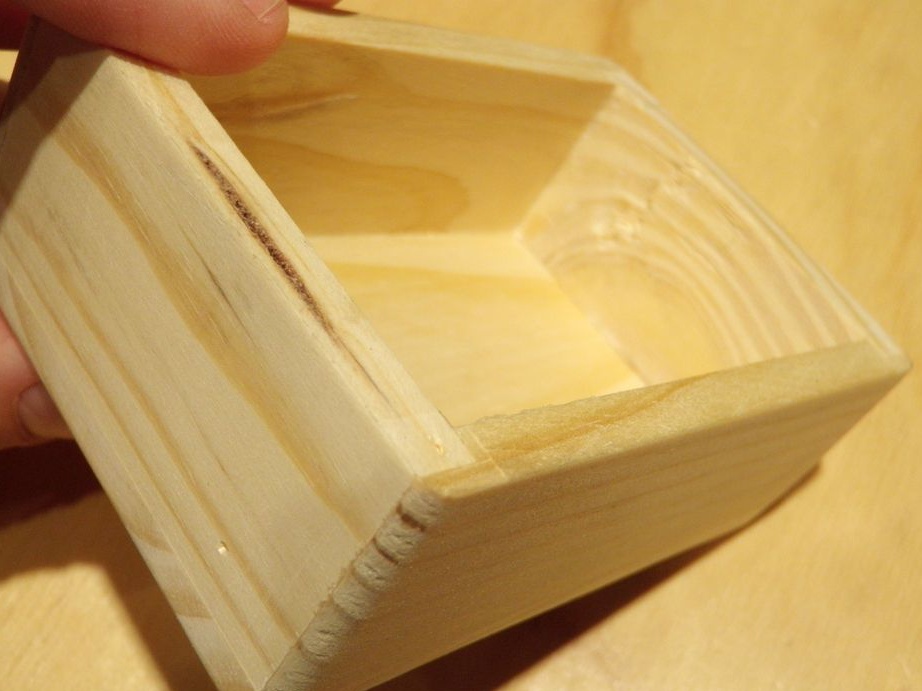
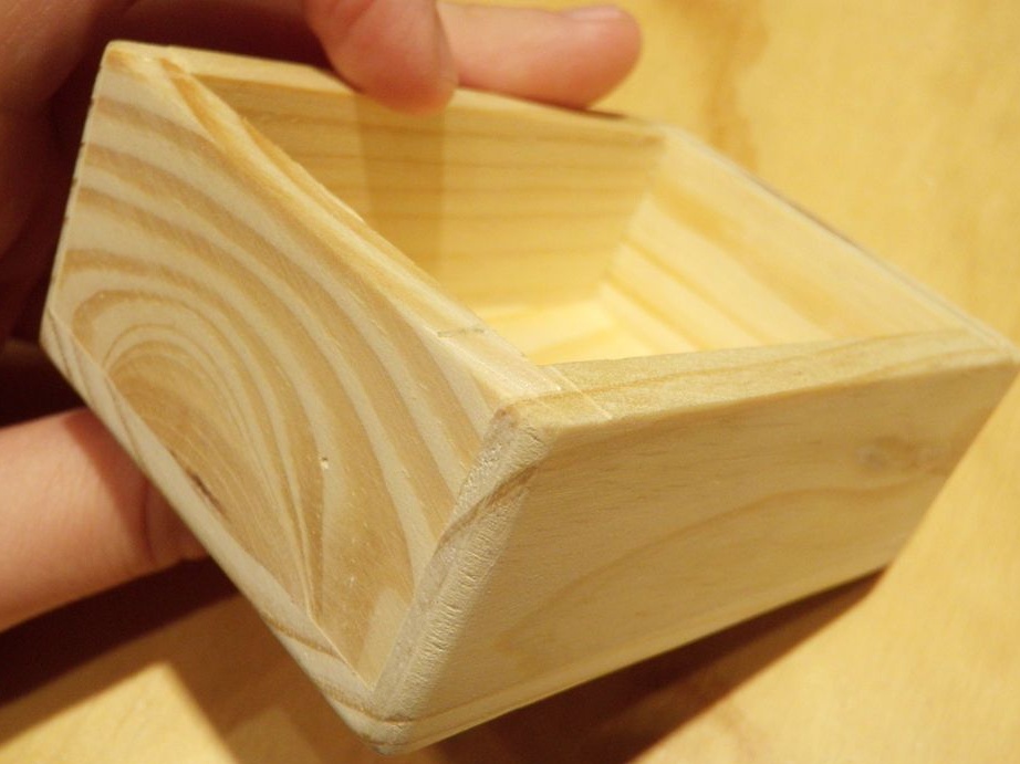
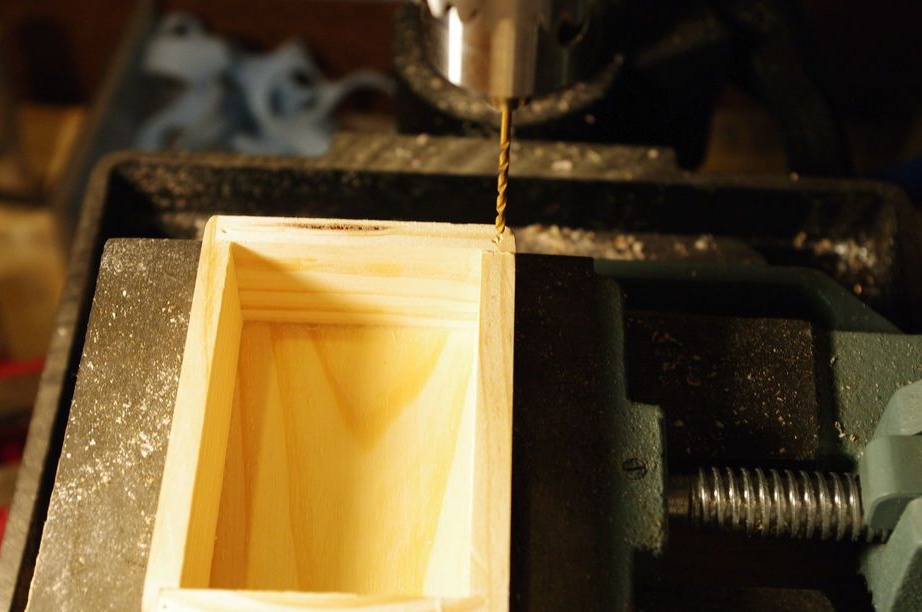
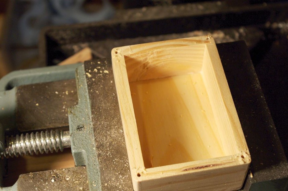
Step Three: Case
The case of the device is a wooden box. In the box, drills a hole for the wire and power connector. Temporarily installs the front panel.
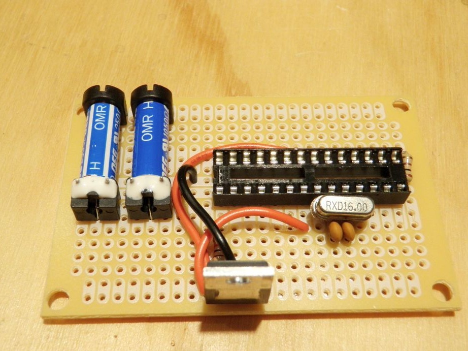
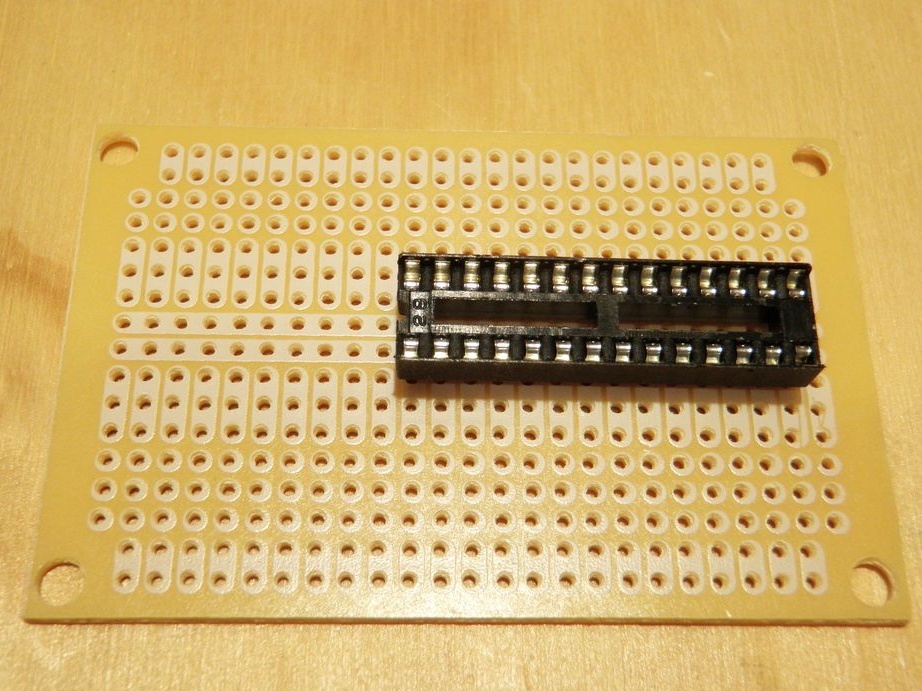
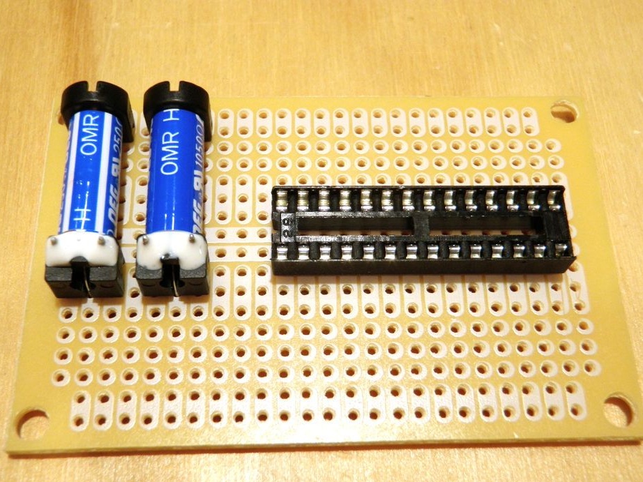
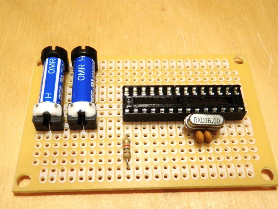
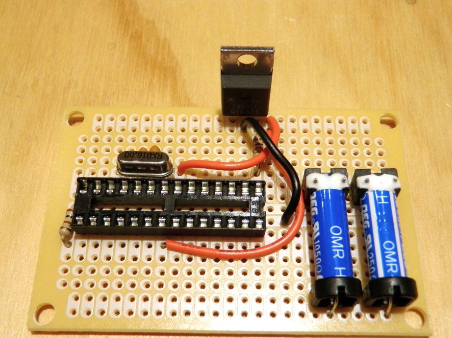
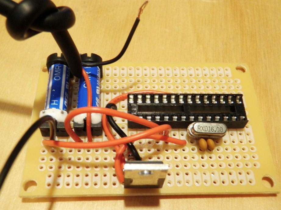
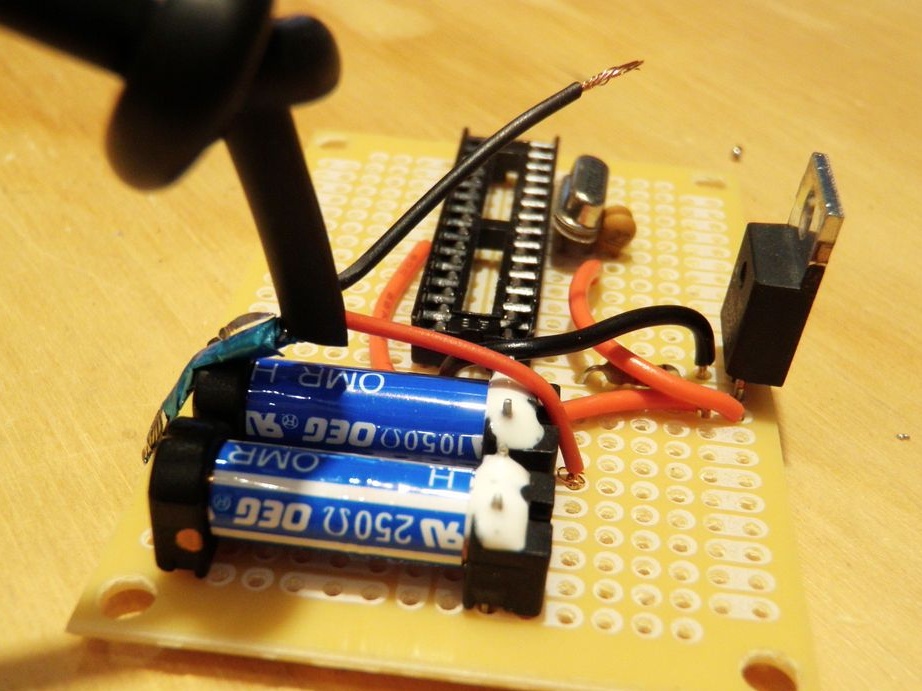
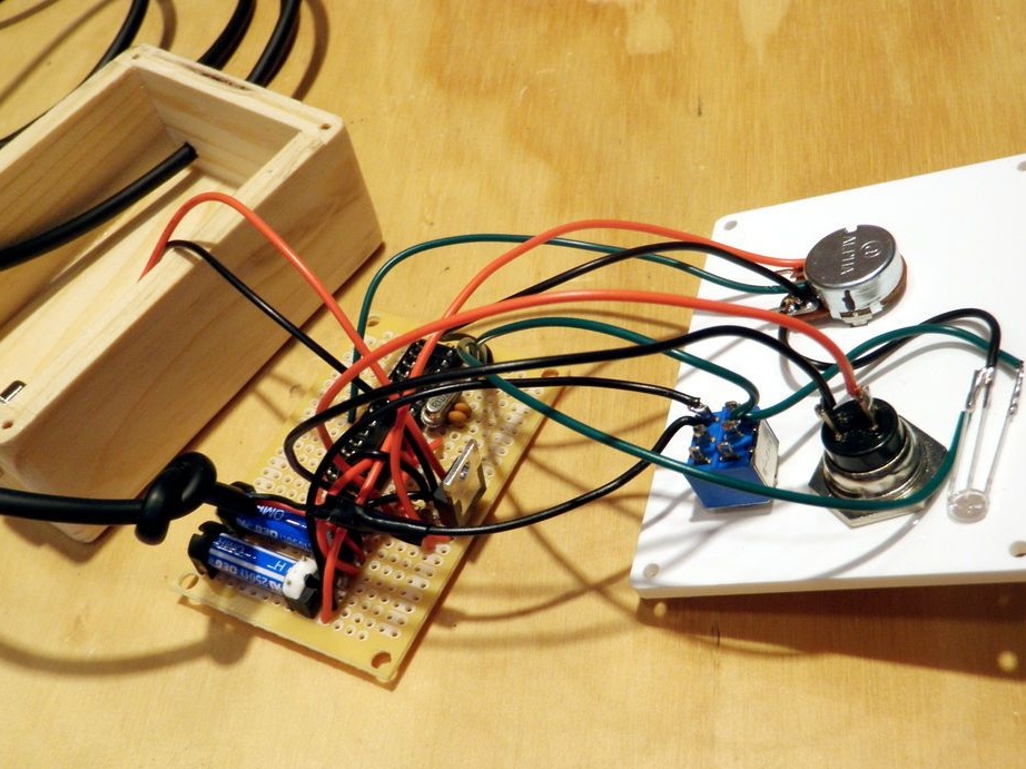
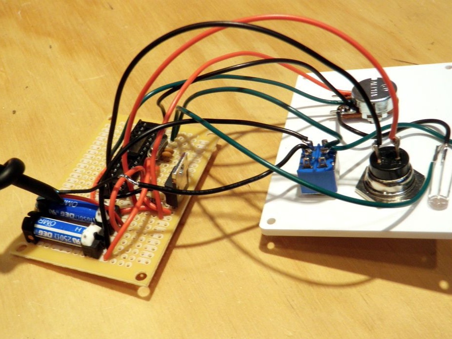
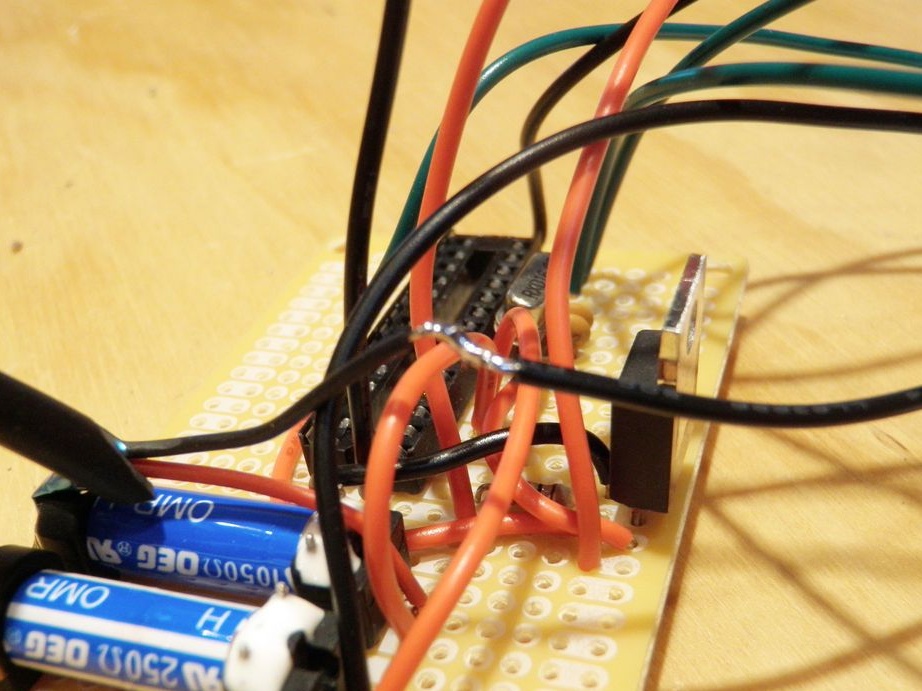
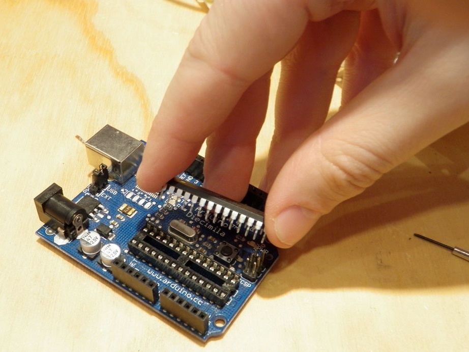
Step Four: Installation
According to the scheme, the installation of parts. In the first step, sets the details as in the photo.

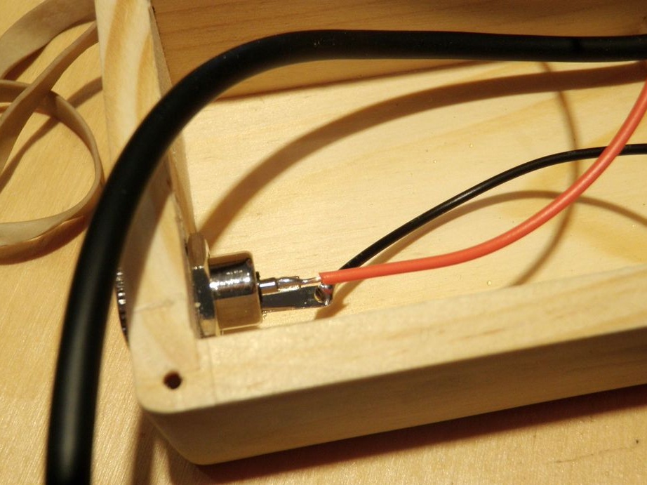
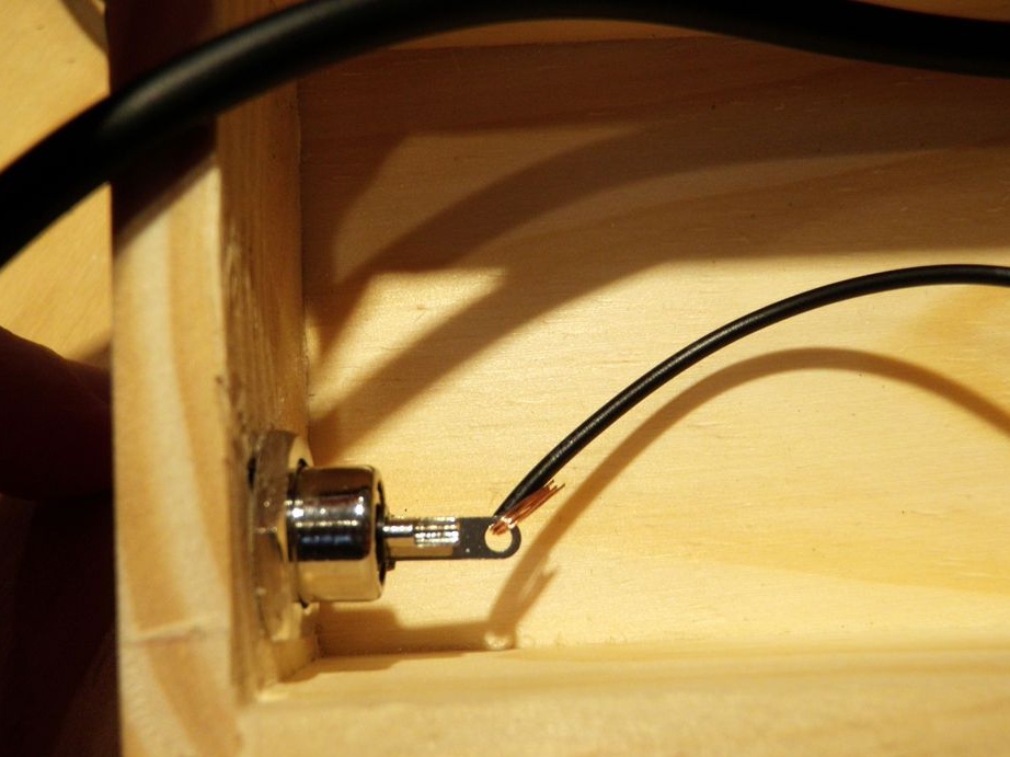
Step Five: Connector
Installs a connector in the chassis. Draws a cable into another hole and knots it.
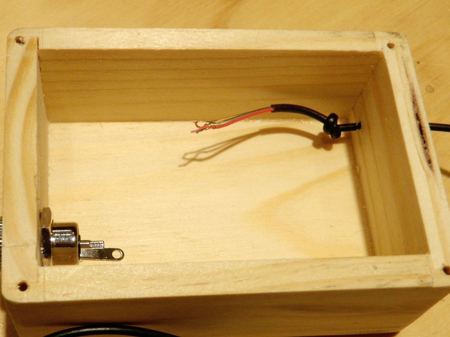
Solder to the wire connector.
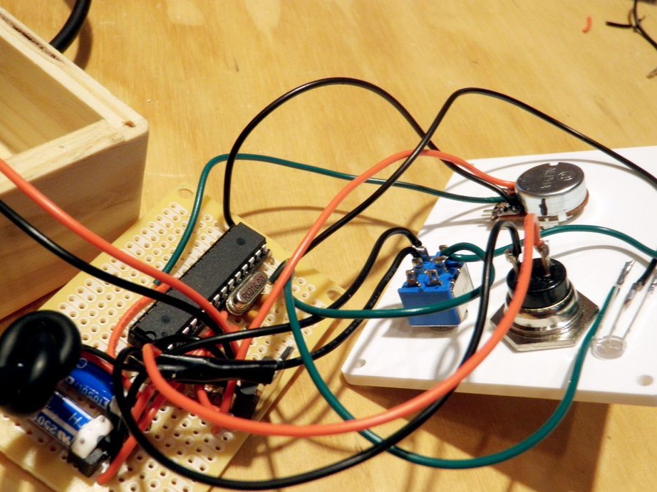
Step Six: Relay Installation
According to the scheme, it establishes and connects the relay contacts.

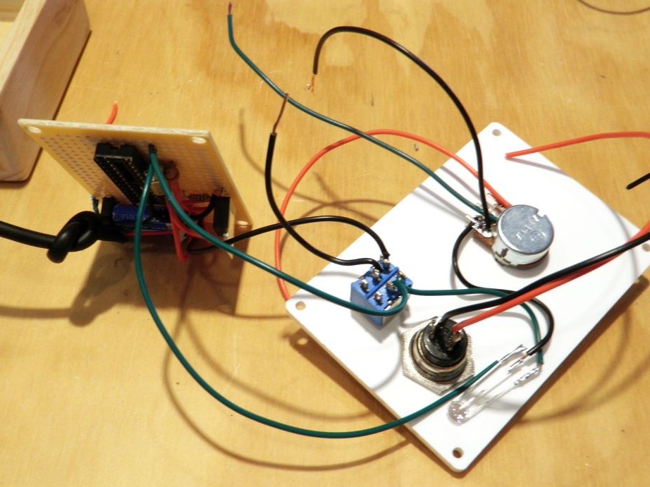
Seventh step: front panel
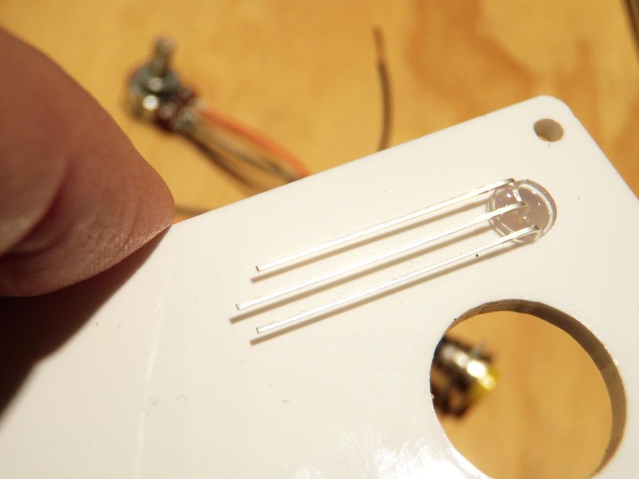
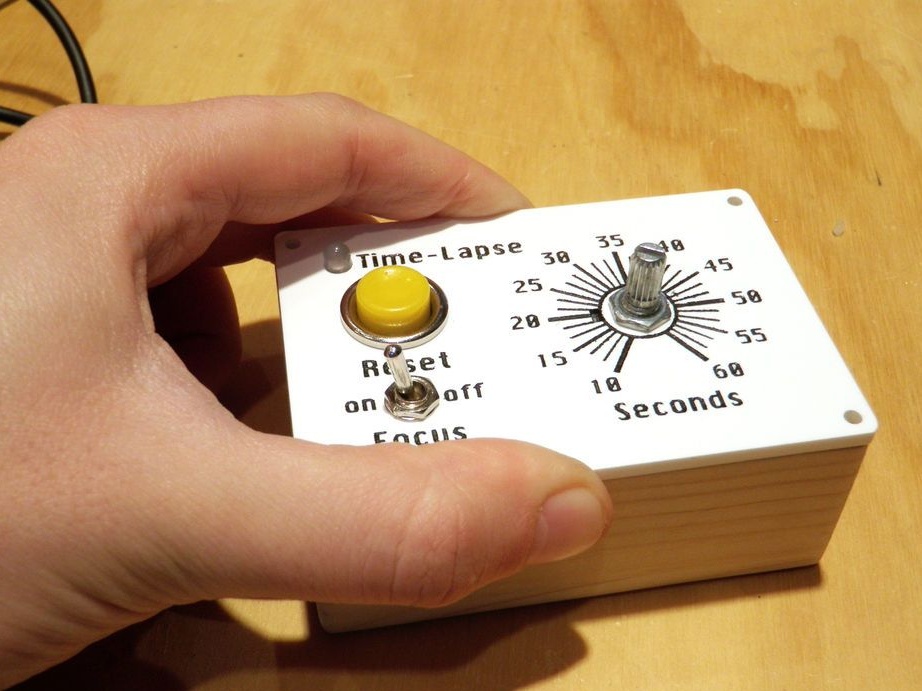
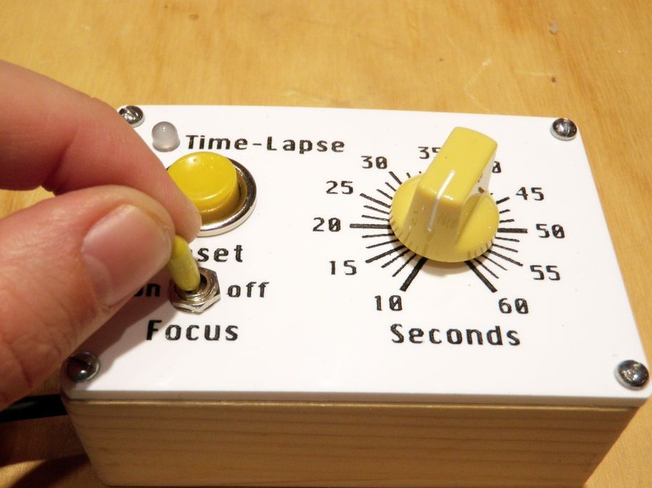
Installs an LED, potentiometer, button and switch on the front panel.
Part of the installation is carried out according to the scheme. The master forgot to draw the second part and described it in words.
Connect the black wire from the stereo wire to one of the center pins on the DPDT toggle switch. Connect the second contact to the relay.
Connect one of the legs from the 2-color LED to the other center pin. Connect the second pin to pin 14 of the Arduino. Further according to the scheme.

Step Eight: Firmware
Loads the code on Arduino. You can download it.
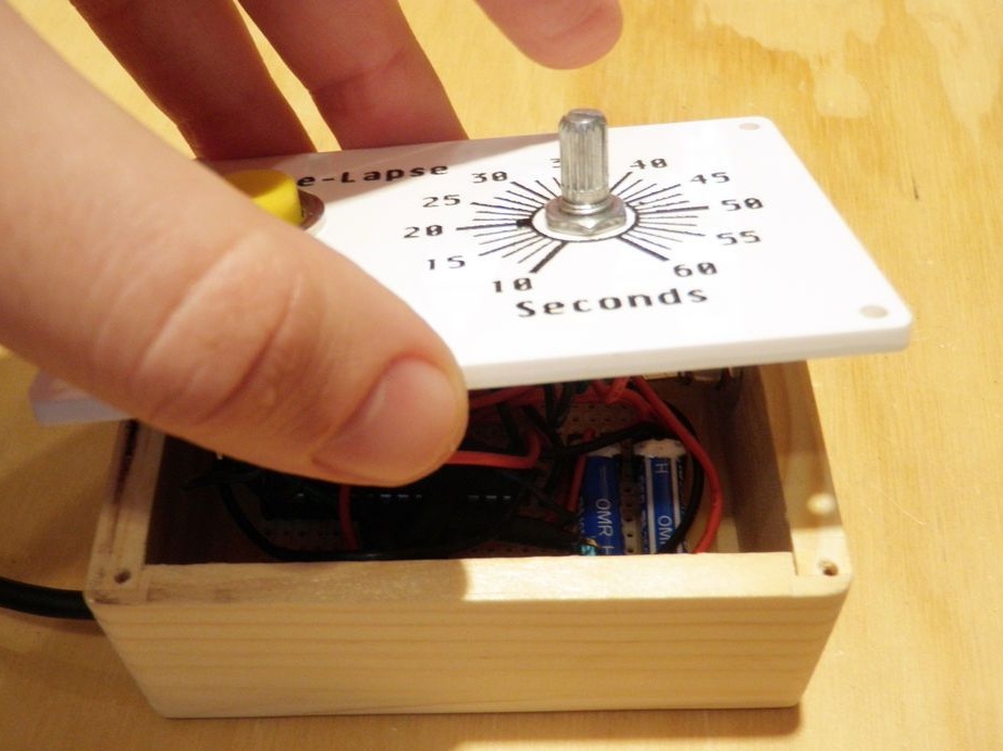
Step Nine: Panel Installation
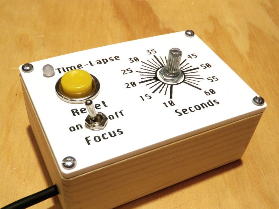
Fastens all parts in the case. Installs the front bezel.
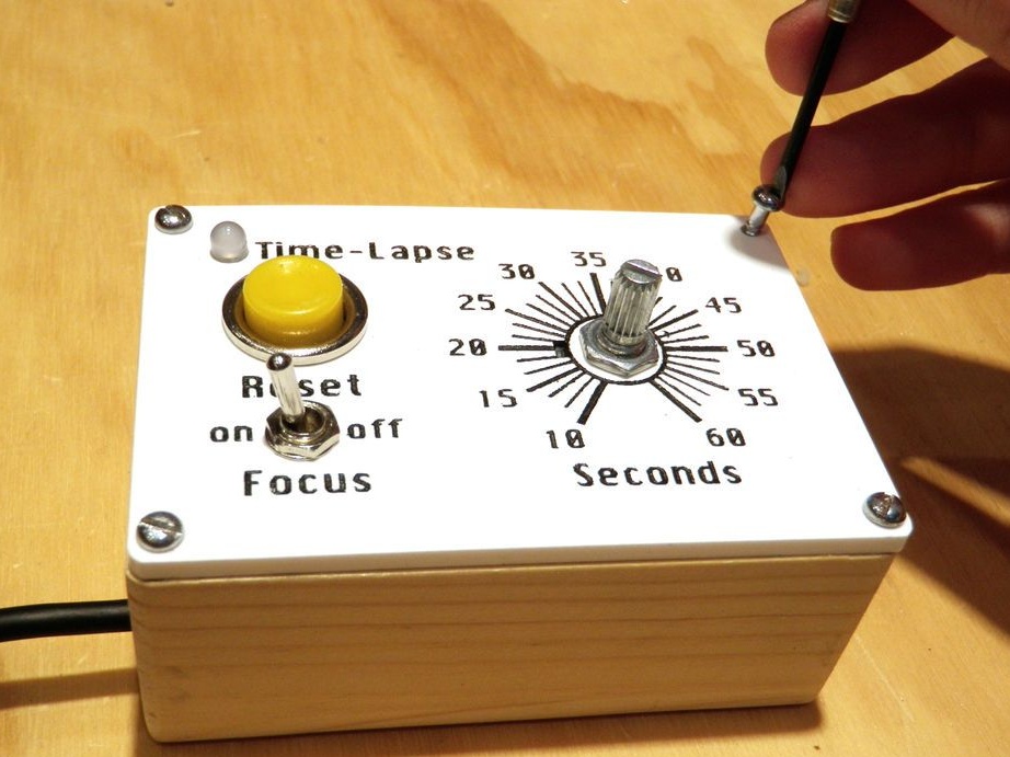
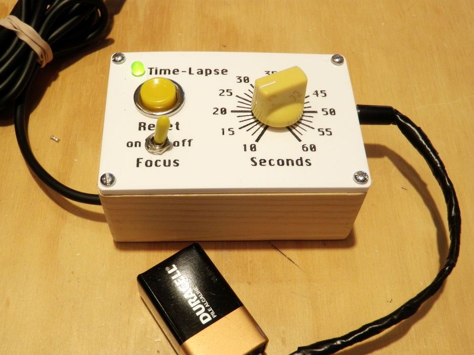
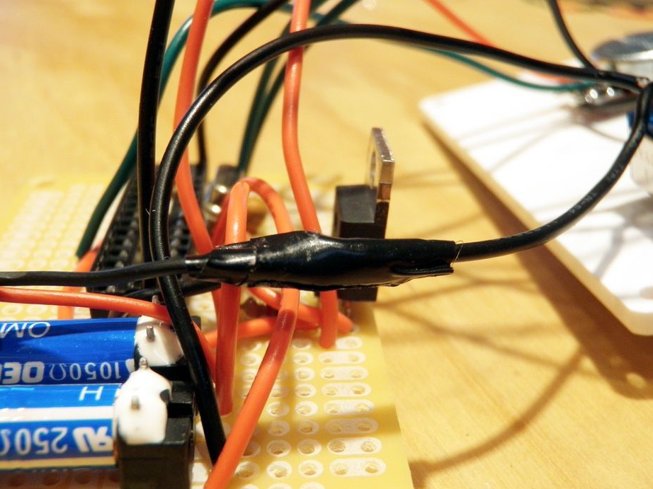
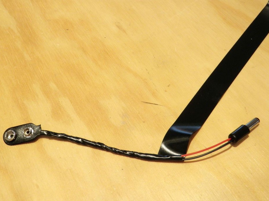
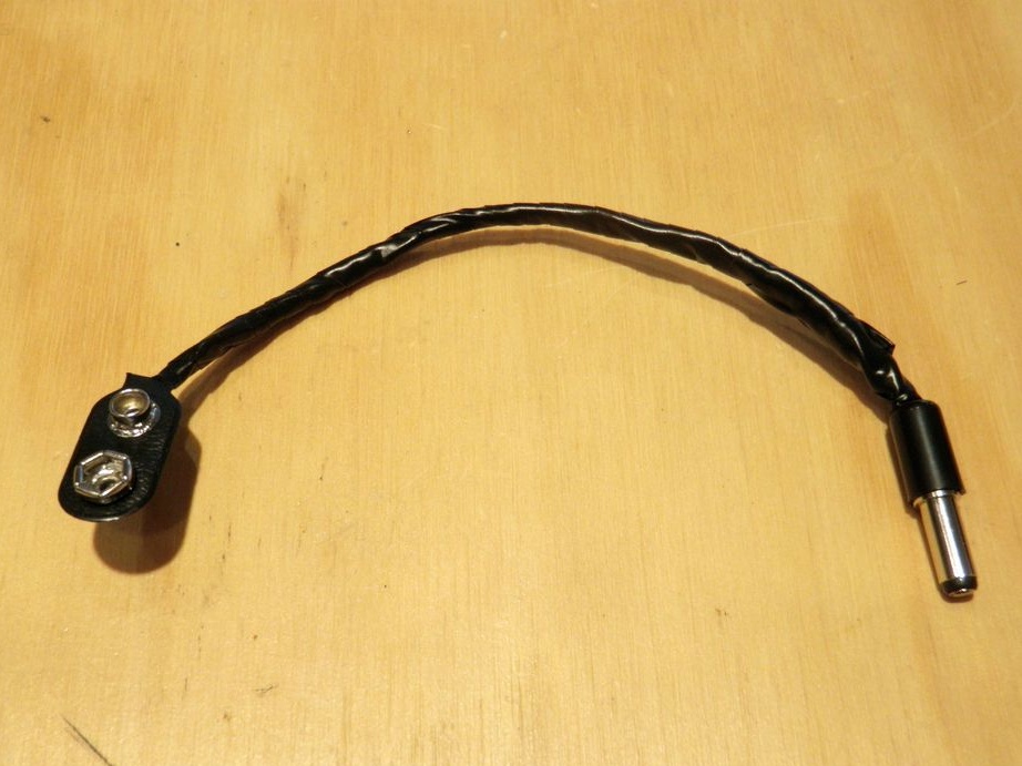
Step Ten: Battery
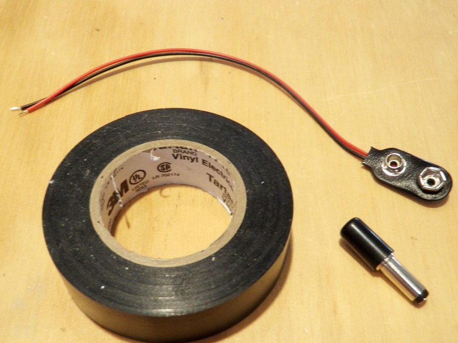
Connects to the wire, on the one hand, the power plug, on the other hand, the battery holder. Installs a battery. Fixes with electrical tape, black. Connects the power plug to the connector.
Now you need to connect the device to the camera connector. Set the interval and press the power button. Focus can be turned off if desired.