Driver - limiter for LED flashlight
In the previous homemade «Rechargeable flashlight - table lamp”Was considered, including the change in the LED matrix in the purchased flashlight. The aim of the revision was to increase the reliability of the light source, by changing the connection diagram of the LEDs, from parallel to combined.
LEDs are much more demanding on a power source than other light sources. For example, an excess of current by 20% will reduce their service life by several times.
The main characteristic of LEDs, which determine the brightness of their glow, is not voltage, but current. In order for the LEDs to work out the declared number of hours with guarantee, a driver is needed that stabilizes the current flowing through the LED circuit and maintains a steady light brightness for a long time.
For low-power light-emitting diodes, it is possible to use them without a driver, but in this case, limiting resistors play its role. Such a connection was used in the above homemade product. This simple solution protects the LEDs from exceeding the permissible current, within the limits of the rated power supply, but there is no stabilization.
In this article, we consider the opportunity to improve the above design and improve the operational properties of a flashlight powered by an external battery.
To stabilize the current through the LEDs, we add a simple linear driver to the lamp design - a current stabilizer with feedback. Here, the current is the leading parameter, and the supply voltage of the LED assembly can automatically vary within certain limits. The driver provides stabilization of the output current with an unstable input voltage or voltage fluctuations in the system, and the current is adjusted smoothly without creating high-frequency interference inherent to pulse stabilizers. The scheme of such a driver is extremely simple to manufacture and configure, but lower efficiency (about 80%) is a fee for this.
To exclude a critical discharge of the power source (below 12 V), which is especially dangerous for lithium batteries, we additionally introduce the indication of the limit discharge or disconnection of the battery at low voltage in the circuit.
Driver Manufacturing
1. To solve these proposals, we will produce the following power supply circuit for the LED matrix.
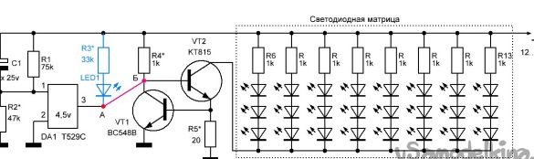
The supply current of the LED matrix passes through the regulating transistor VT2 and the limiting resistance R5. The current through the control transistor VT1 is set by the selection of the resistance R4 and can vary depending on the change in the voltage drop across the resistor R5, also used as a current feedback resistor. When the current in the circuit increases, the LEDs, VT2, R5, for any reason, increase the voltage drop across R5. The corresponding increase in voltage on the basis of the transistor VT1, opens it, thereby reducing the voltage on the basis of VT2. And this covers the transistor VT2, reducing and stabilizing this, the current through the LEDs. With a decrease in current on the LEDs and VT2, the processes proceed in the reverse order. Thus, due to feedback, when the voltage at the power source changes (from 17 to 12 volts) or possible changes in the circuit parameters (temperature, failure of the LED), the current through the LEDs is constant during the entire battery discharge period.
On the voltage detector, a specialized chip DA1, a device for voltage control is assembled. The microcircuit works as follows. At rated voltage, the DA1 chip is closed and is on standby. When the voltage decreases at terminal 1 connected to the controlled circuit (in this case, the power source) to a certain value, terminal 3 (inside the microcircuit) is connected to terminal 2 connected to a common wire.
The above diagram has various switching options.
Option 1. If we connect the indicator LED (LED1 - R3) connected to the positive wire to terminal 3 (point A) (see the circuit diagram), we get an indication of the maximum discharge of the battery. When the supply voltage drops to a certain value (in our case 12 V), LED1 will turn on, signaling the need for a battery charge.
Option 2 If point A is connected to point B, then when a low voltage (12 V) is reached on the battery, we will automatically disconnect the LED matrix from the power supply. The voltage detector, chip DA1, when the control voltage is reached, connects the base of the transistor VT2 with a common wire and closes the transistor by disconnecting the LED matrix. When the flashlight is turned on again at low voltage (less than 12 V), the matrix LEDs light up for a couple of seconds (due to charge / discharge C1) and turn off again, signaling the battery is low.
Option 3When combining options 2 and 3, when the LED matrix is turned off, the LED1 will turn on.
The main advantages of the voltage detector circuits are the simplicity of the circuit connection (almost no additional strapping parts are required) and the extremely low power consumption (microamp amperes) in standby state (in standby mode).
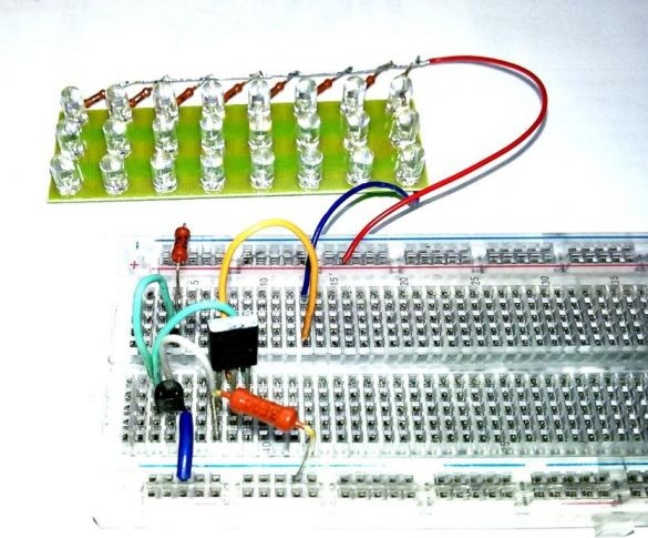
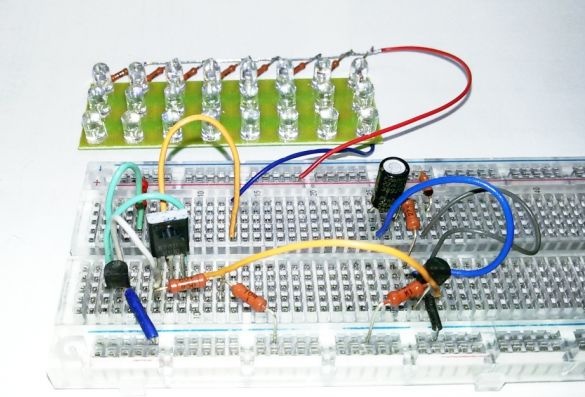
2. We assemble the driver circuit on the circuit board.
We carry out the installation of VT1, VT2, R4. We connect, as a load, the LED matrix, considered at the beginning of the article. We include a milliammeter in the power supply circuit of the LEDs. In order to check and adjust the circuit at a stable and specific voltage, we connect it to an adjustable power source. We select the resistance of the resistor R5, which allows to stabilize the current through the LEDs in the entire range of the planned adjustment (from 12 to 17 V). In order to increase the efficiency, the R5 resistor was initially installed with a nominal value of 3.9 ohms (see photo), but the stabilization of the current in the entire range (with parts actually installed) required a nominal value of 20 ohms, since there was not enough voltage to adjust VT1 from for low current consumption of the LED matrix.
The transistor VT1 is desirable to choose with a large base current transmission coefficient. Transistor VT2 must provide an acceptable collector current in excess of the current of the LED matrix and the operating voltage.
3. Add the indicator circuit - limiter limiter to the circuit board. The voltage detector microcircuits are available for various voltage control values. In our case, due to the lack of a 12 V microcircuit, I used the available one at 4.5 V (often found in used household appliances - televisions, video recorders). For this reason, to control the voltage of 12 V, we add to the circuit a voltage divider for the constant resistor R1 and variable R2, which is necessary for fine-tuning to the desired value. In our case, by adjusting R2, we achieve a voltage of 4.5 V at pin 1 of DA1 at a voltage of 12.1 ... 12.3 V on the power bus. Similarly, when selecting a voltage divider, you can use other similar microcircuits - voltage detectors, various companies, names and control voltages.
Initially, we check and configure the circuit to operate according to the LED indicator. Then we check the operation of the circuit by connecting points A and B to turn off the LED matrix. We stop on the selected option (1, 2, 3).
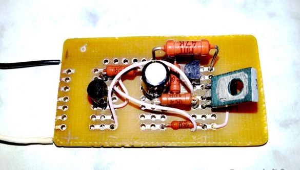
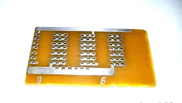
4. We prepare the blank for the working board by cutting out the desired size from a typical universal board.
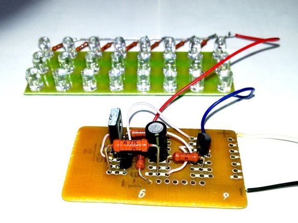
5. We carry out the wiring of the debugged circuit to the working board.
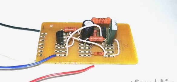
6. We connect the LED matrix to the working board and check the operation of the driver - limiter assembly, in the entire range of the planned adjustment (from 12 to 17 V), connecting the driver to an adjustable power source. With positive results, we check the operation of the driver connected to the battery and as part of the battery lamp. Additional setup is usually not required.