

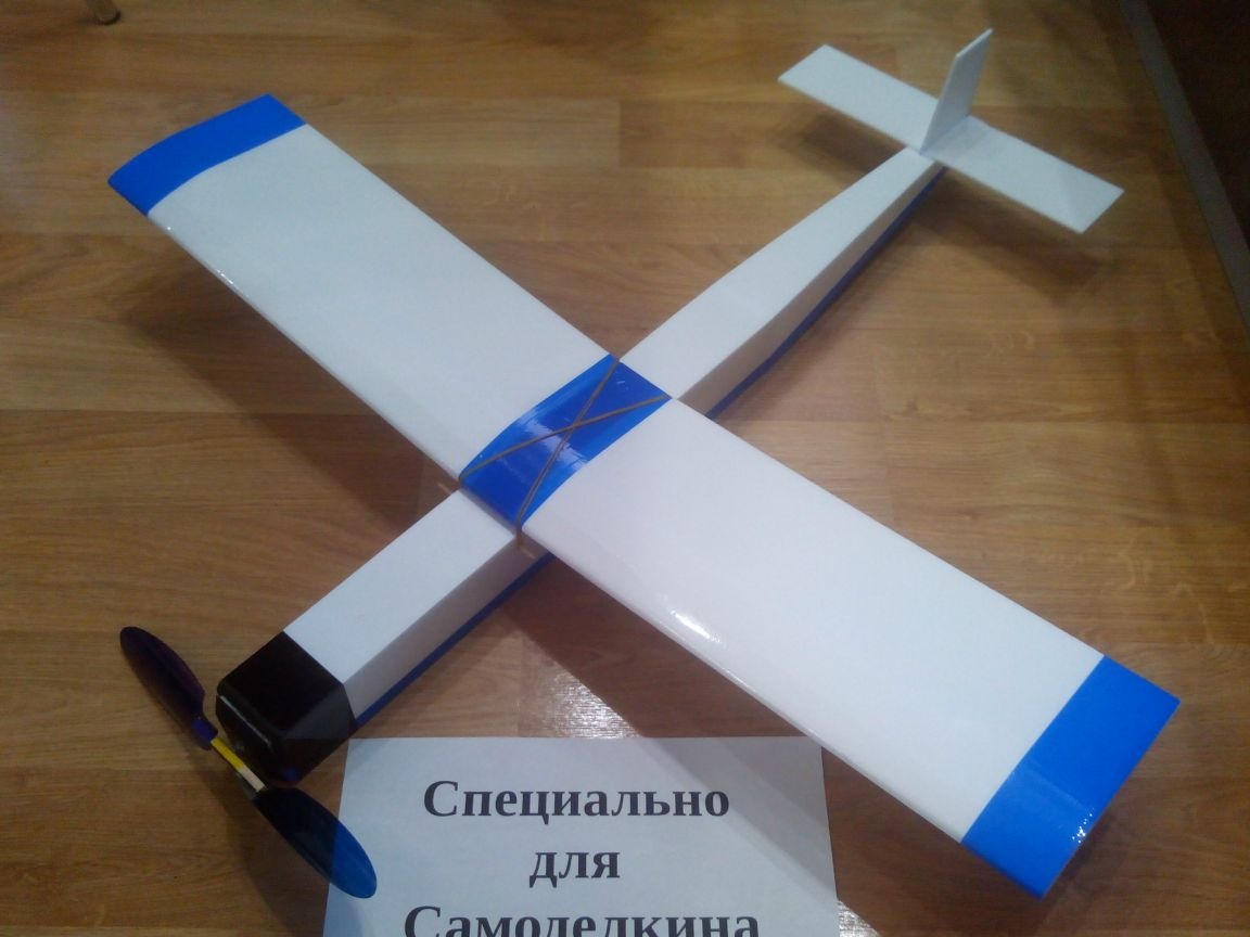
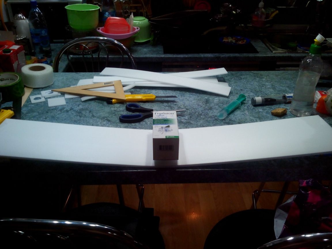
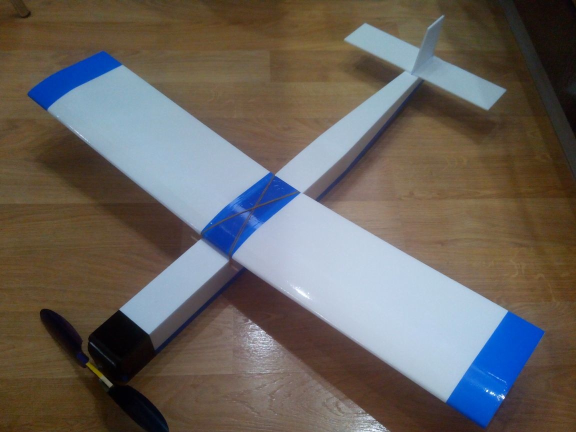
This article describes the manufacture of a large rubber-motor model with a volumetric fuselage and a wing span of slightly less than 1 meter. Model made of ceiling tiles using plywood and battens. The manufacturing technology is simple, and therefore every student can repeat such a model.
Materials:
- ceiling tile
- reiki
- thin plywood
- steel wire
- threads
- fishing tires
- plastic bottle
- adhesive tape
- bamboo skewers
- serpyanka
- rubber bands for money
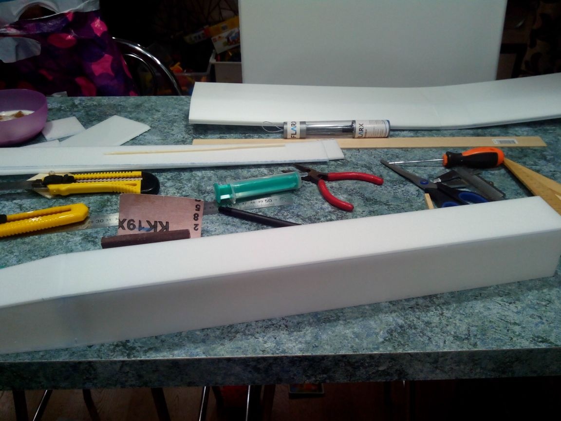
Instruments:
- ceiling adhesive, PVA and epoxy (five-minute)
- cutter
- awl
- sandpaper
- screwdriver and drill
- pliers
- nippers
- jigsaw
- a pen
- ruler
- square
- scissors
The dimensions of this model were selected, so to speak, for the available material, and therefore there is no drawing with specific dimensions. But the general principle of construction will be clear. Some sizes will be indicated in the text.
Step 1. Making a wing.
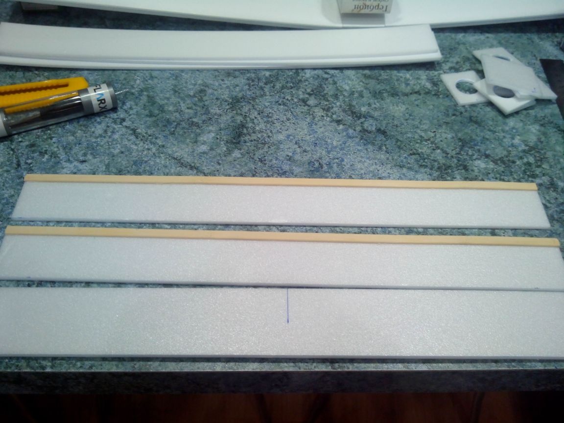
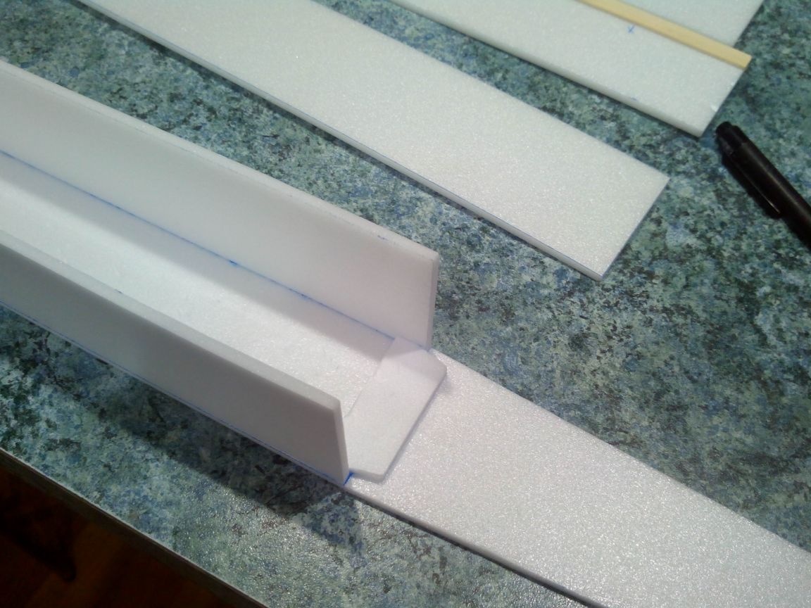
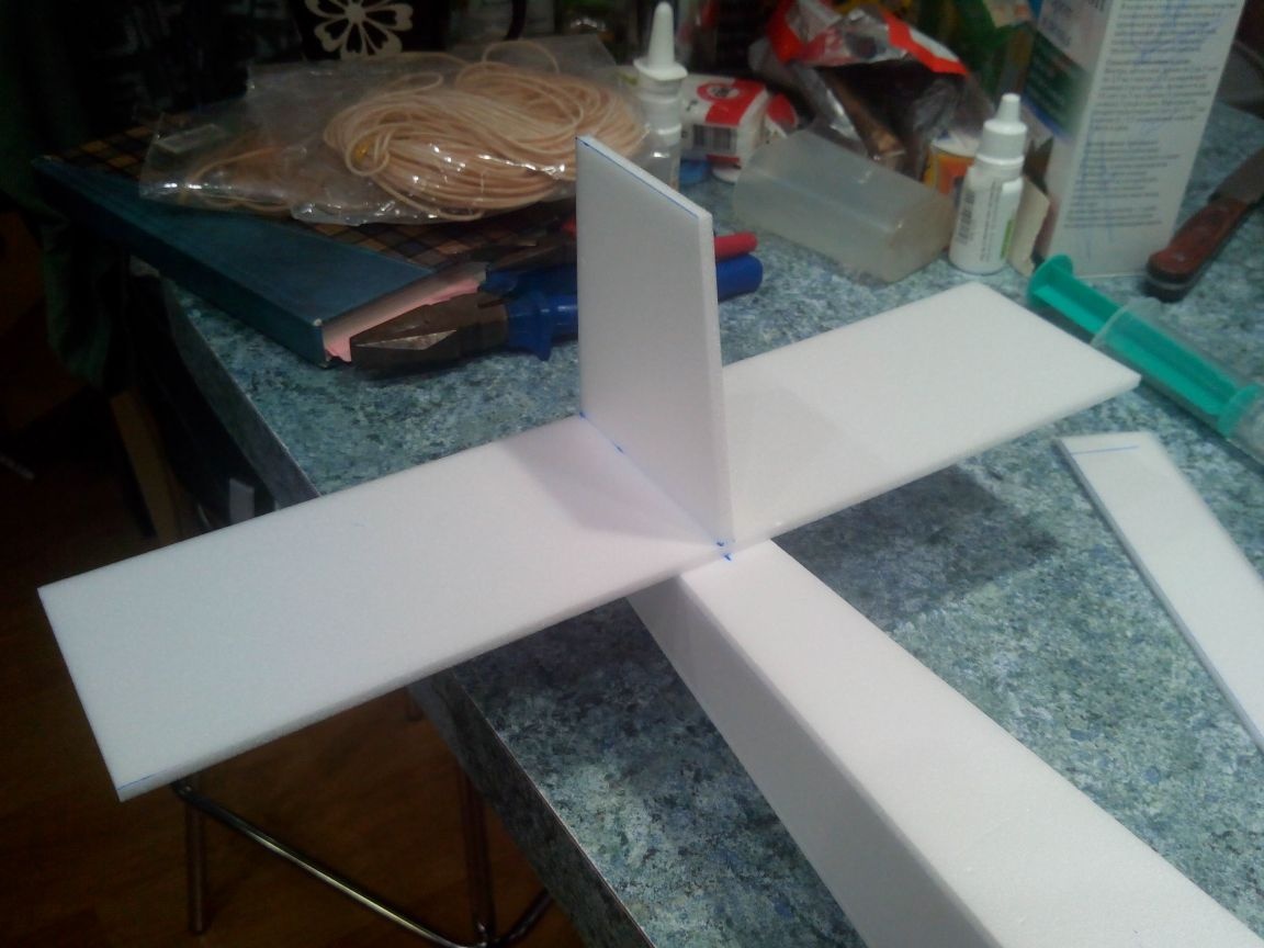
We cut out the consoles (400x150 mm - 4 pieces) and the front edge (370x10 mm - 2 pieces) from the ceiling tile, and glue the edges to the lower parts of the consoles.
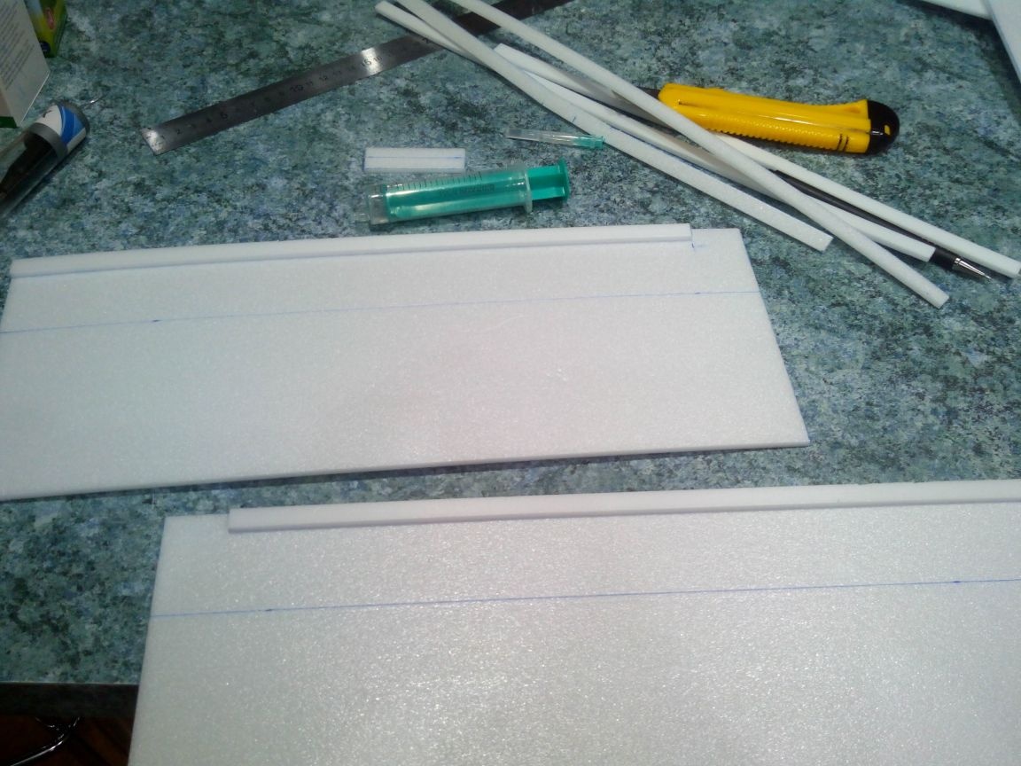
Glue the lower parts together and add a piece of the ceiling in front. The line is the position of the wing spar.
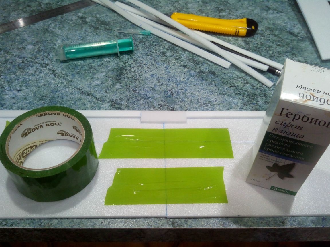
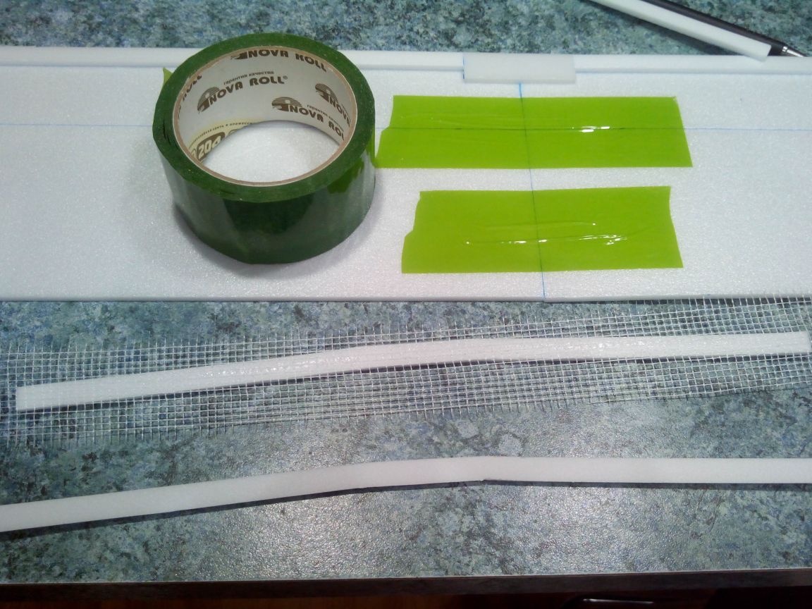
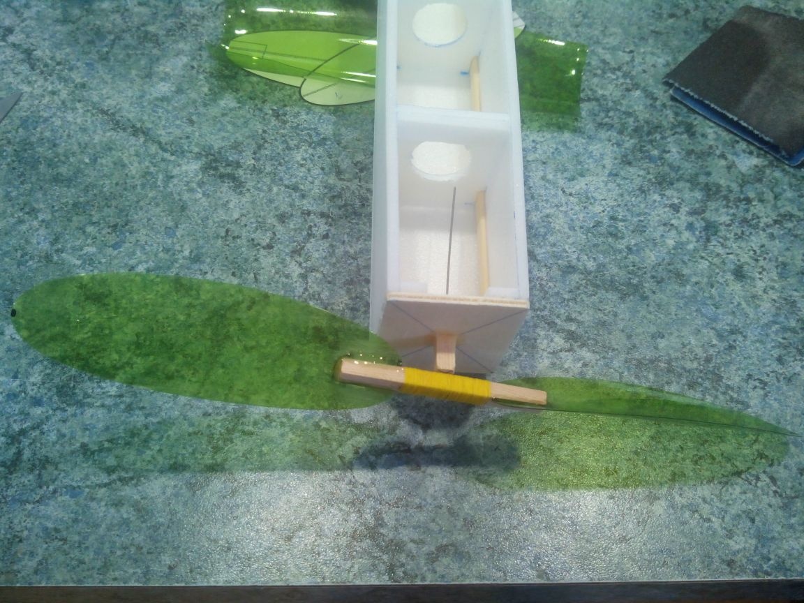
The spar itself is also from the ceiling (width 10 mm). To make the transverse angle V, we cut out two V-shaped blanks from the ceiling and reinforce one of them with a serpentine.
We glue the spar.
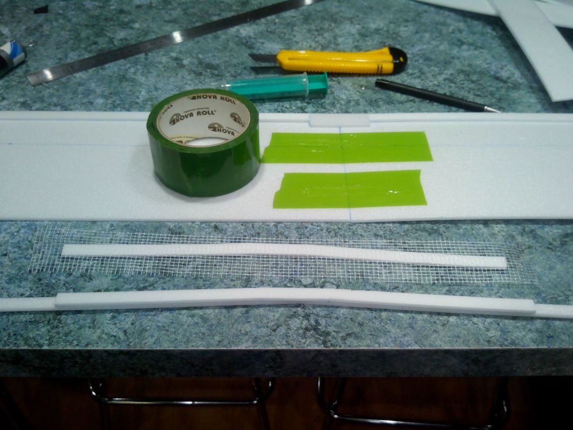
And cut off the excess sickle.
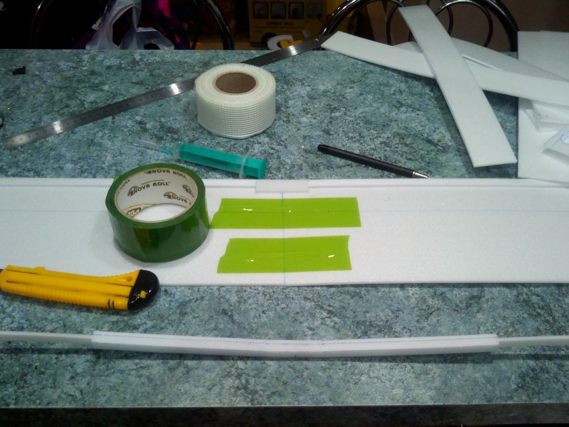
Glue the spar to the lower plane of the wing.
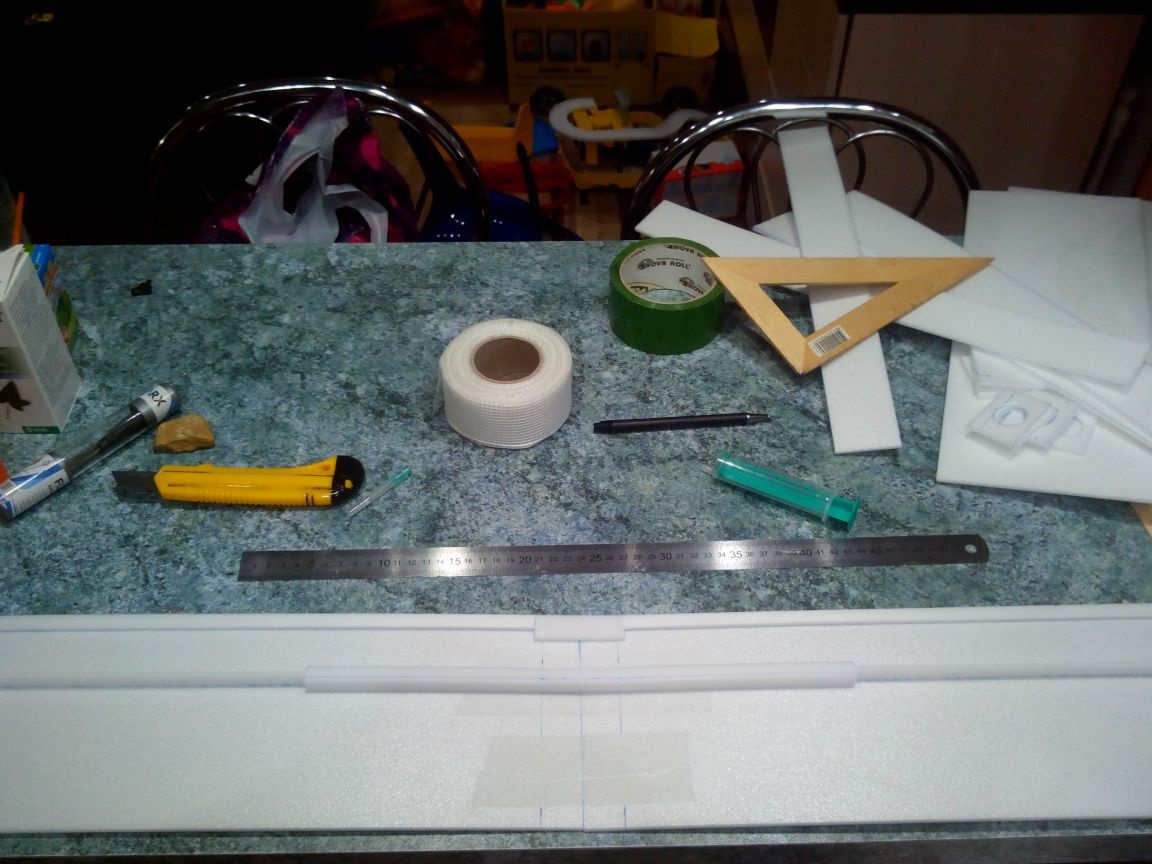
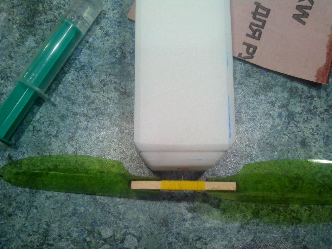
We strengthen the joint of the consoles with a serpentine and coat it with ceiling glue on top.
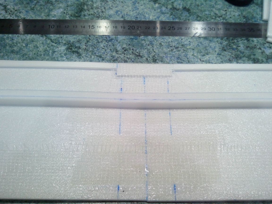
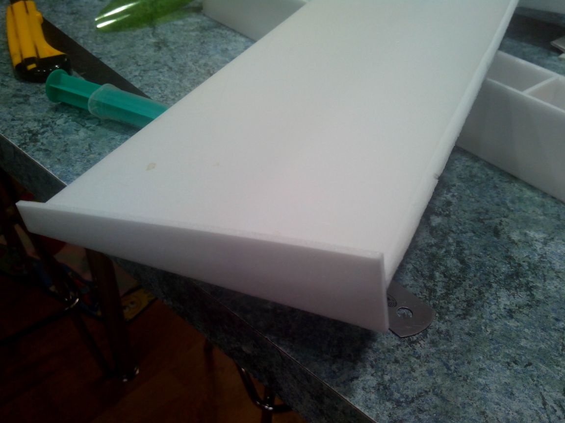
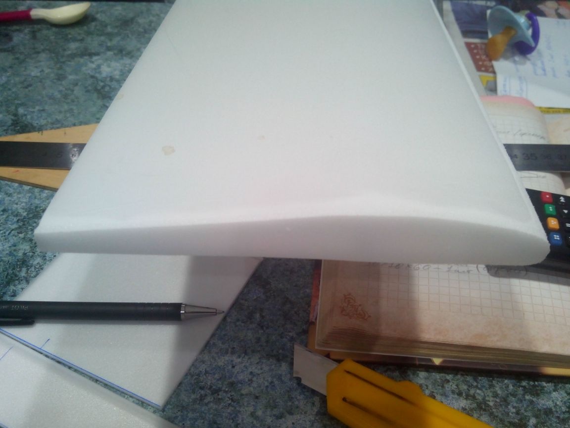
The upper parts of the wing (375x150 mm - 2 pieces) are bent on the pipe or on the edge of the table and glued to the lower part. The center section is cut from the ceiling (150x48 mm) and glued, greasing the joints with glue. It is better to dry over a small load by placing books or other objects under the wing ends so that the wing takes its final shape.
Round off the front edge of the wing with sandpaper and glue the wingtips.
After the glue dries, we cut off the excess and level it with sandpaper.
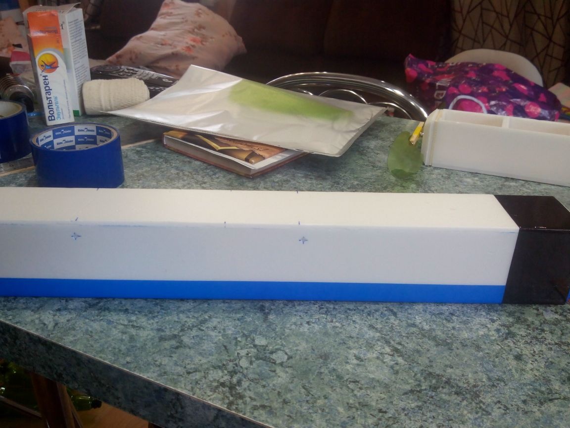
Step 2. Making the fuselage.
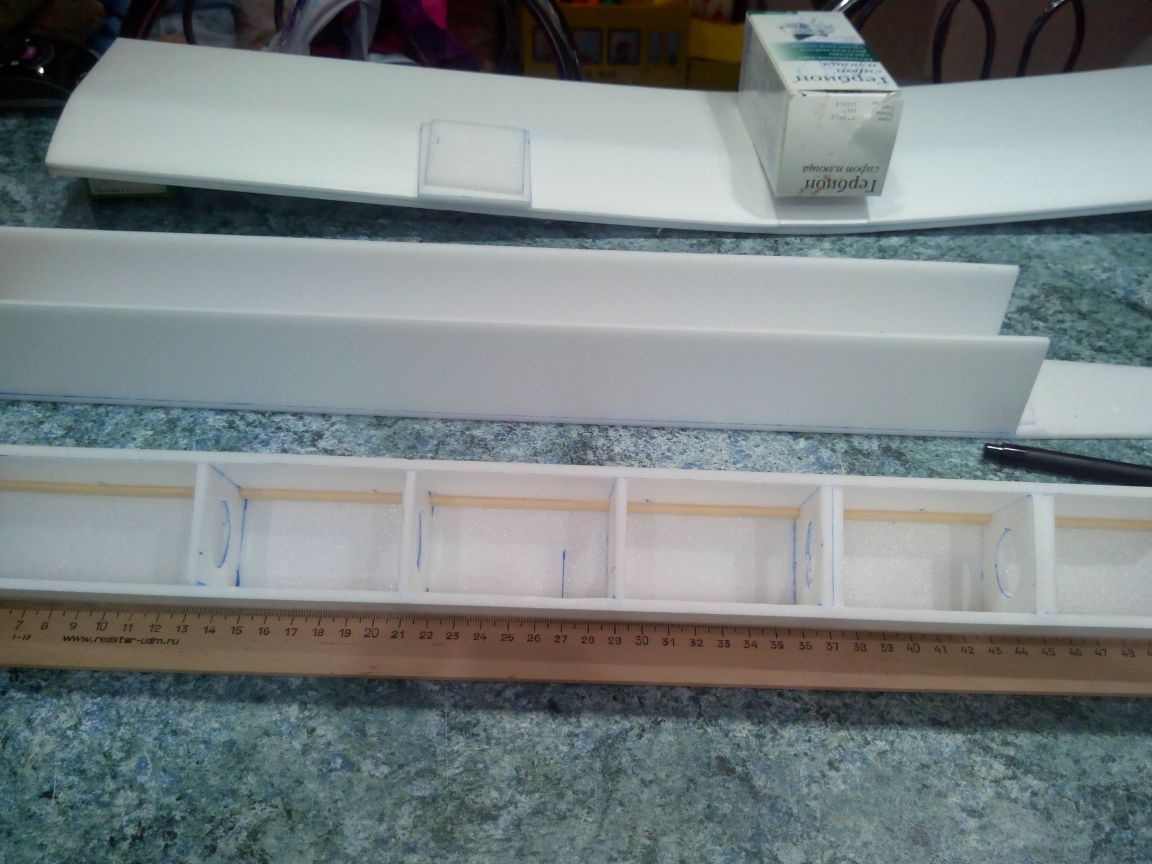
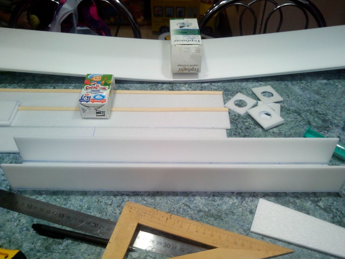
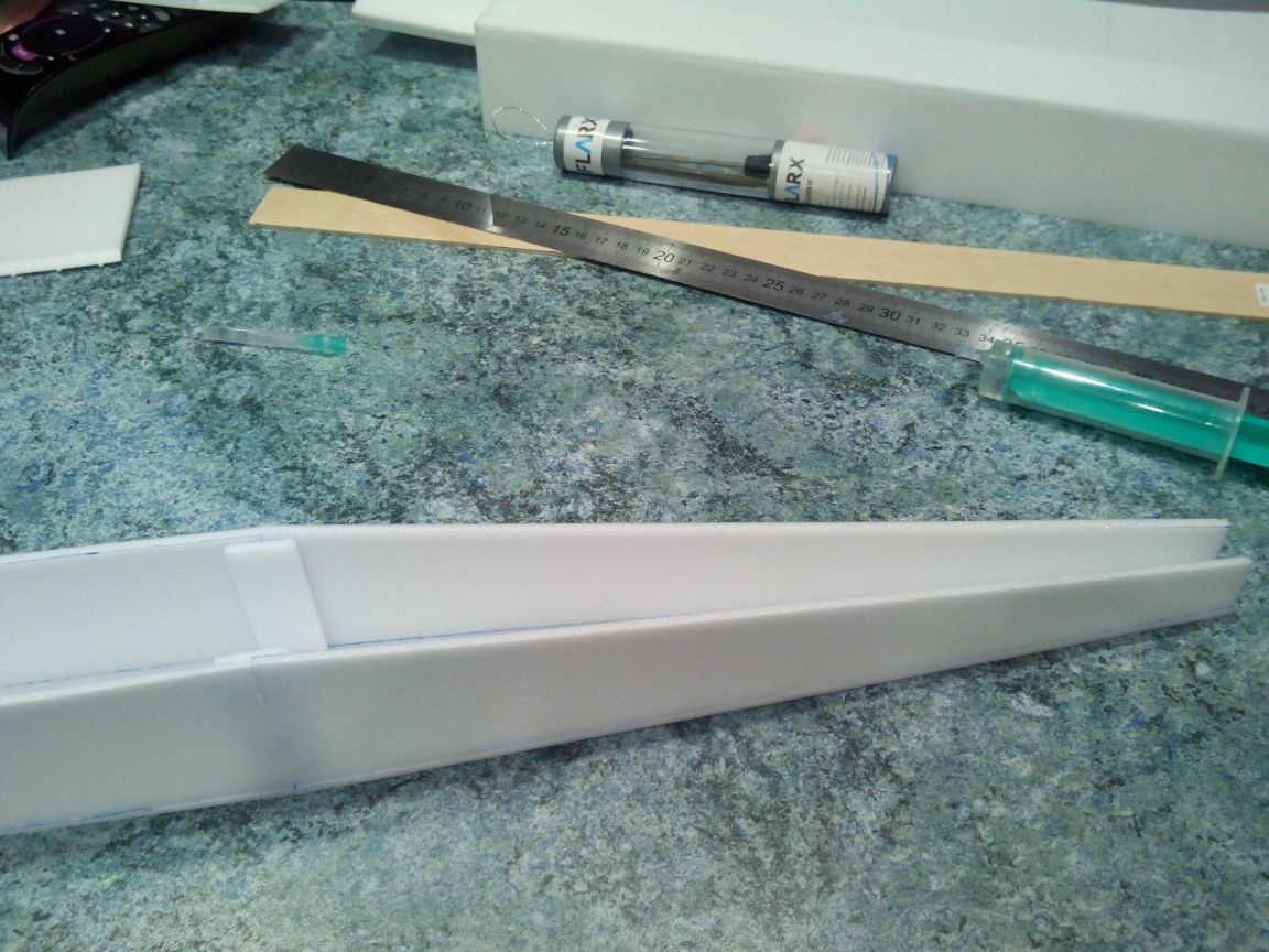
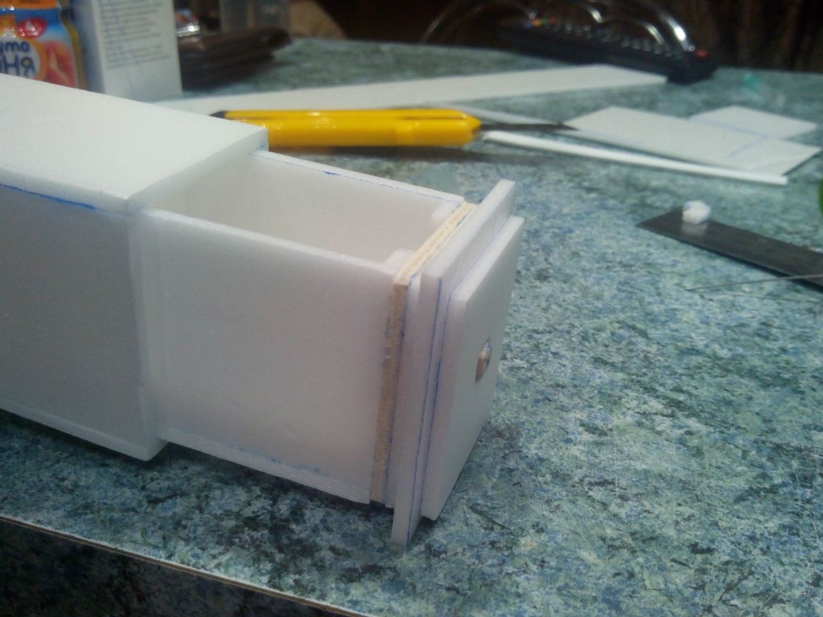
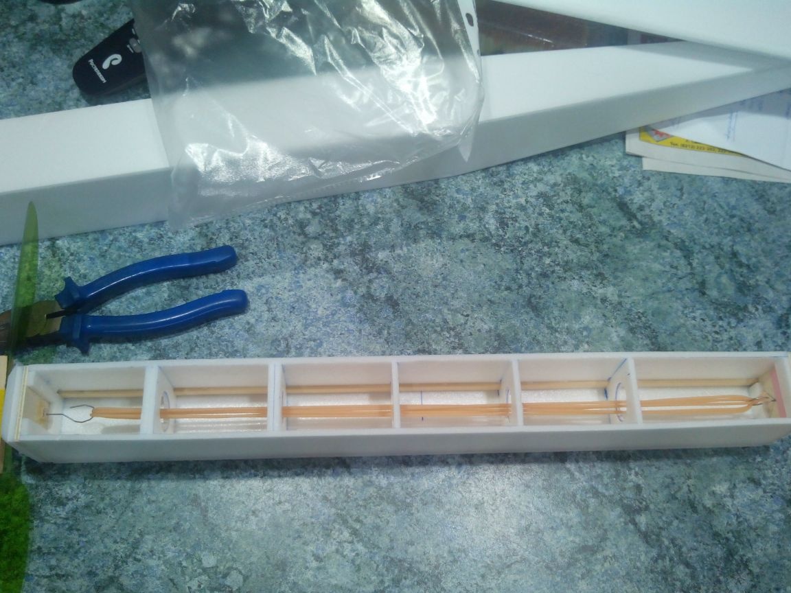
First, glue the motor compartment. It is a box reinforced with slats and with plywood frames at the ends.
We glue the rails to the sides of the motor compartment.
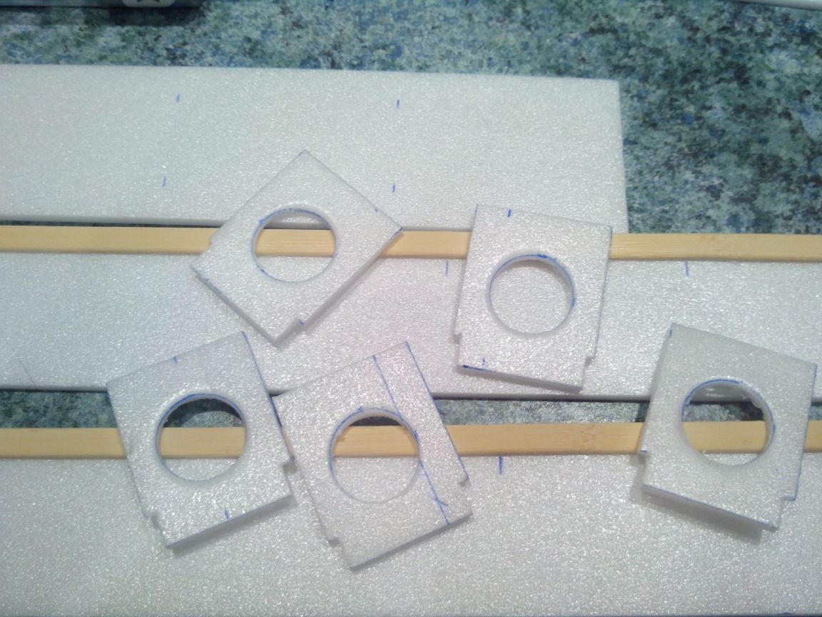
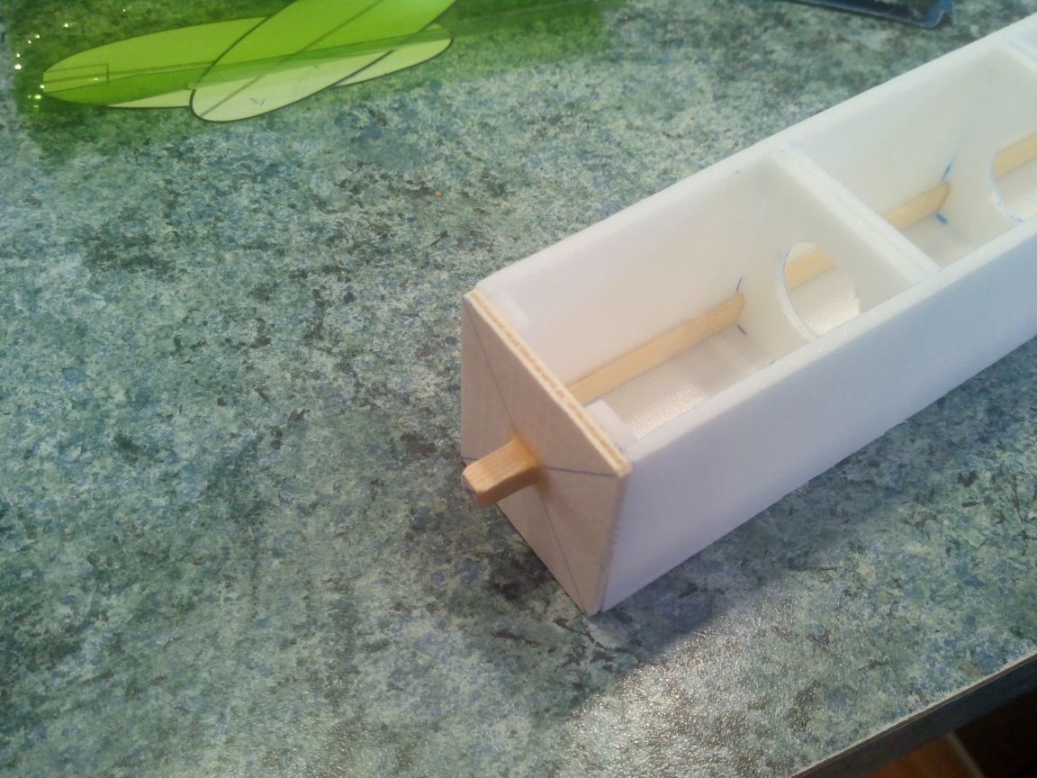
We prepare the frames, making holes and cutouts for the slats in them. The holes are conveniently made with a suitable diameter cap.
We glue the motor compartment and glue the ceiling frames.
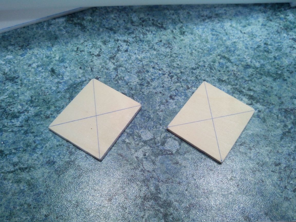
We cut out the bow and stern frames from plywood.
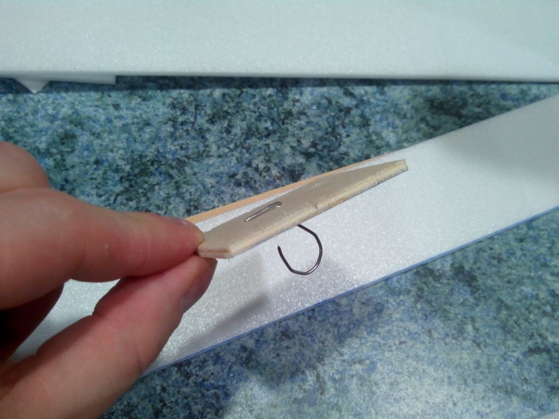
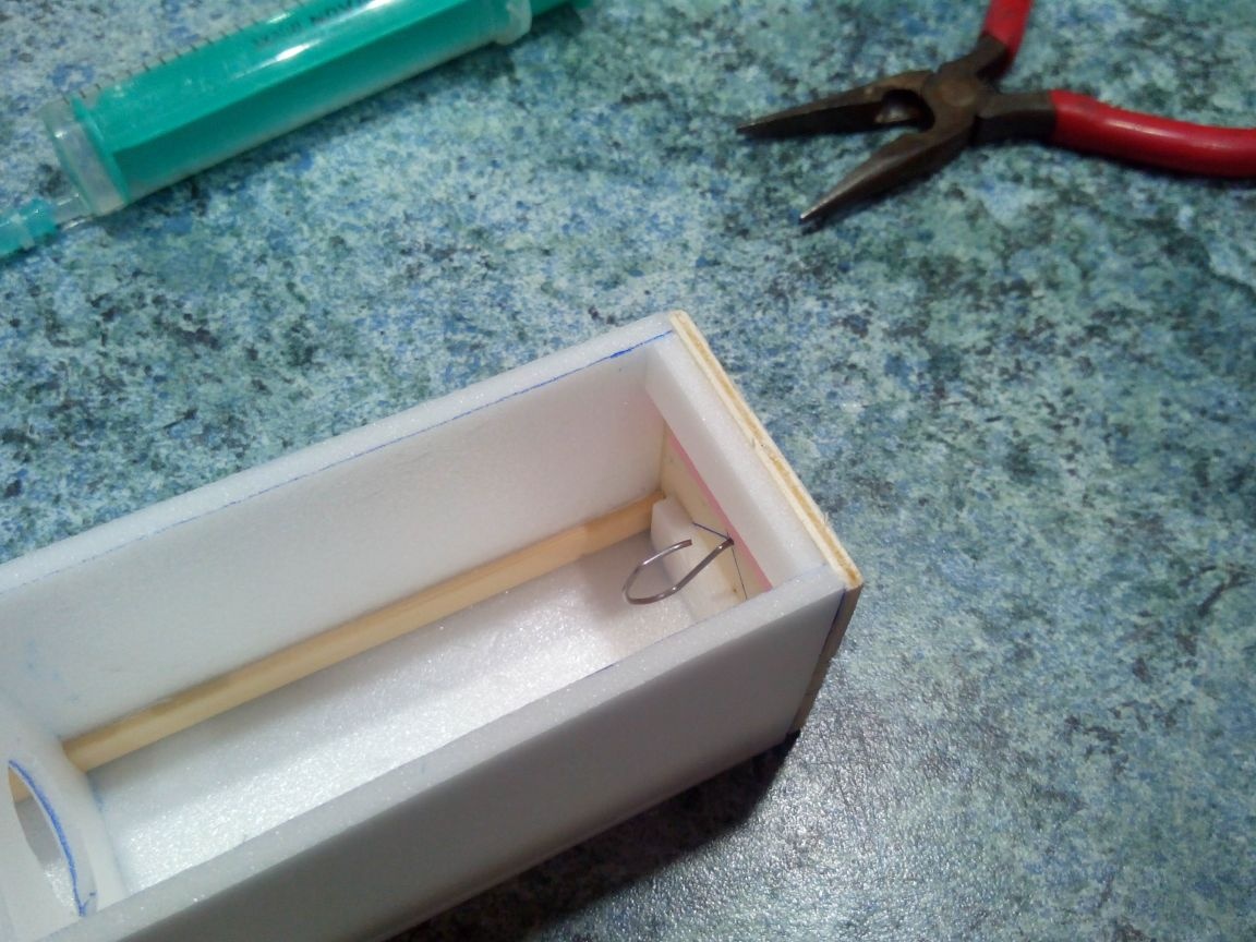
From the wire we make the rear hook and fix it in the rear frame (through the hole).
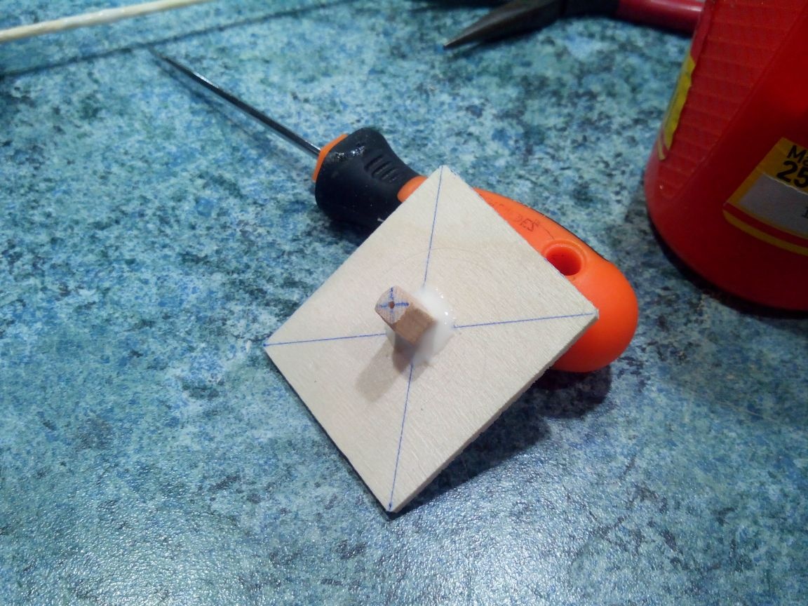
From a wooden block we cut the boss and glue it with a small slope into the nose frame (after making a hole). We drill a hole under the screw axis in a boss with a thin drill.
Glue the back frame with a hook.
Glue the front frame with the boss.
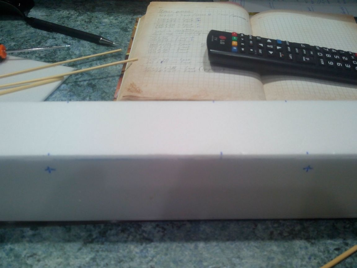
The fuselage box, in which the motor compartment will be located, is glued from the ceiling. In size, the box should be such that it fits tightly but effortlessly into the engine compartment.
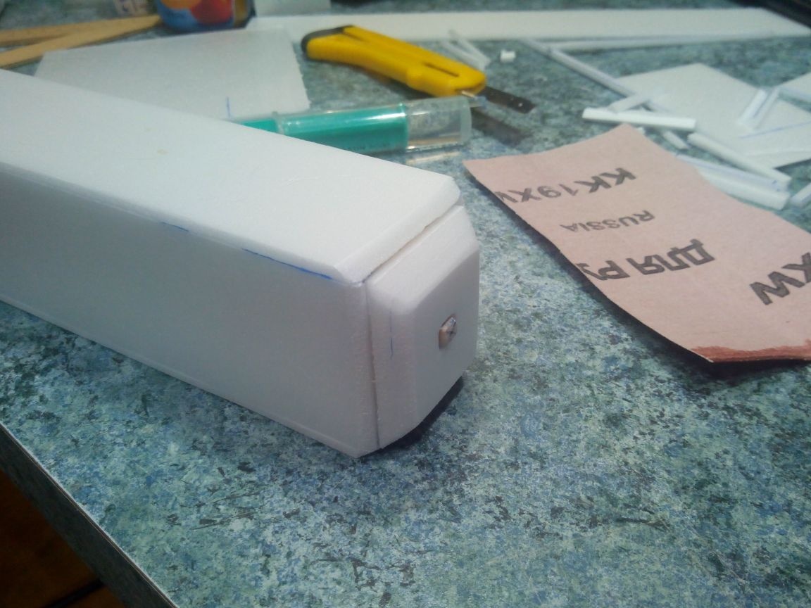
Glue the top of the tail and reinforce the junction of the ceiling strip. These strips of ceilings at the joints will also be limiters, so that the engine compartment does not fall heavily into the fuselage.
Similarly, glue the sides of the tail and the bottom.
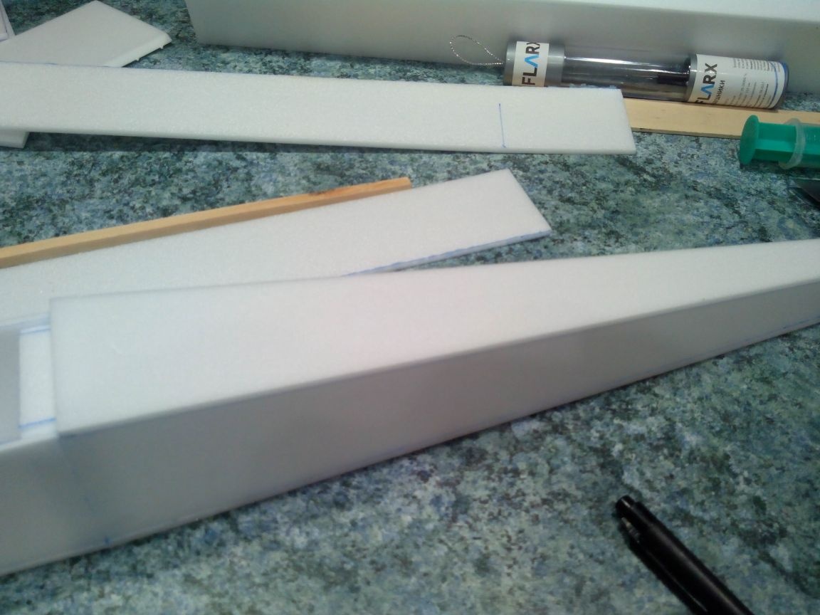
We seal the bottom of the fuselage.
We attach several layers of ceiling tiles to the engine mount.
Then cut at an angle and sanded, giving a little streamlined nose.
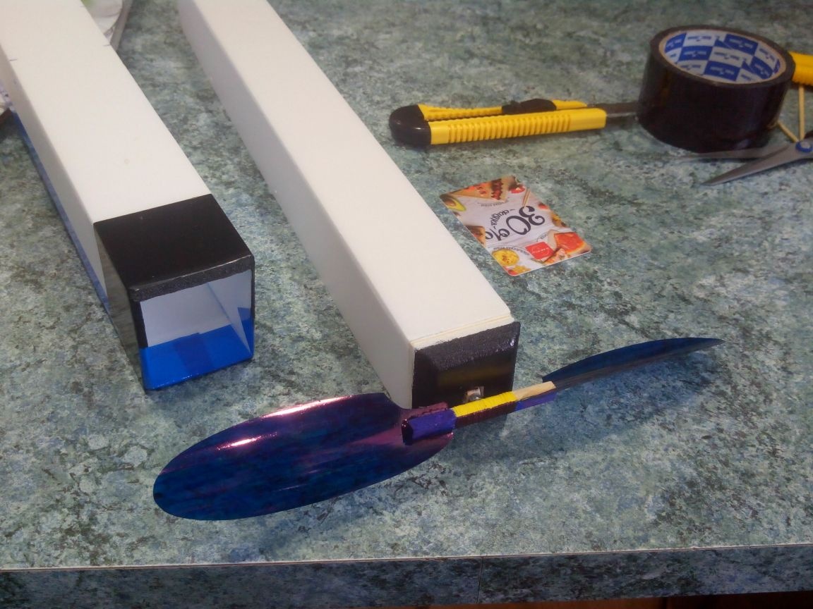
Step 3. Production of screw and tail.
The screw will be made of a wooden battens (hub) and a plastic bottle (blades).
First you need to draw a pattern of blades. The easiest way to do this is in the office editor by drawing an “ellipse” shape of a given size (height 12 cm, width 4 cm), and print the desired amount.
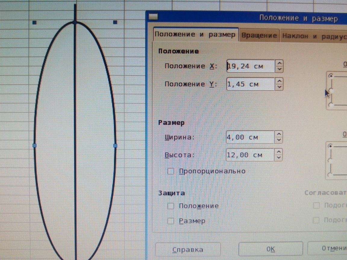
Then we cut out the templates of the blades and glue it with adhesive tape to an even plastic bottle. I recommend that you make a marker on the back side of the label in advance so that the screw can be glued evenly.
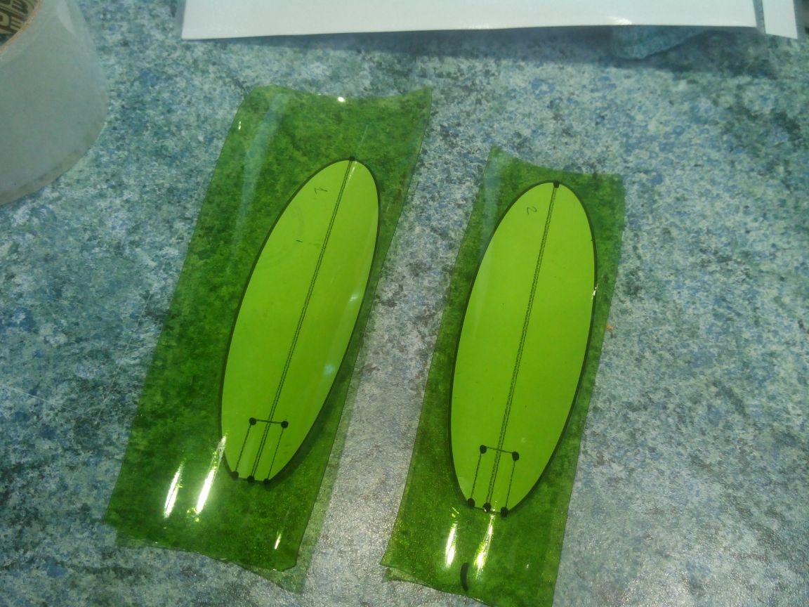
We cut the blades with scissors and sand the place of gluing them to the hub.
We cut the hub out of the rack (length 60 mm) and drill a hole for the shaft. We bend the shaft from steel wire, insert it into the hole and wind it with thread with PVA glue.
We make cuts under the blades with a jigsaw.
Glue the blades with five-minute epoxy glue.
So that the blades do not cling to the nose of the fuselage, we slightly cut them with scissors.
We insert the screw shaft into the boss in the engine mount and bend the hook for the rubber motor from the inside. We use a small nut as a washer. We thread the rubber motor through the frames and hook onto the hooks.
The tail is made of one layer of ceiling tiles. The dimensions of the stabilizer are 300x70 mm, the dimensions of the keel are 70x80 mm.
Step 4. Alignment, assembly and gluing.
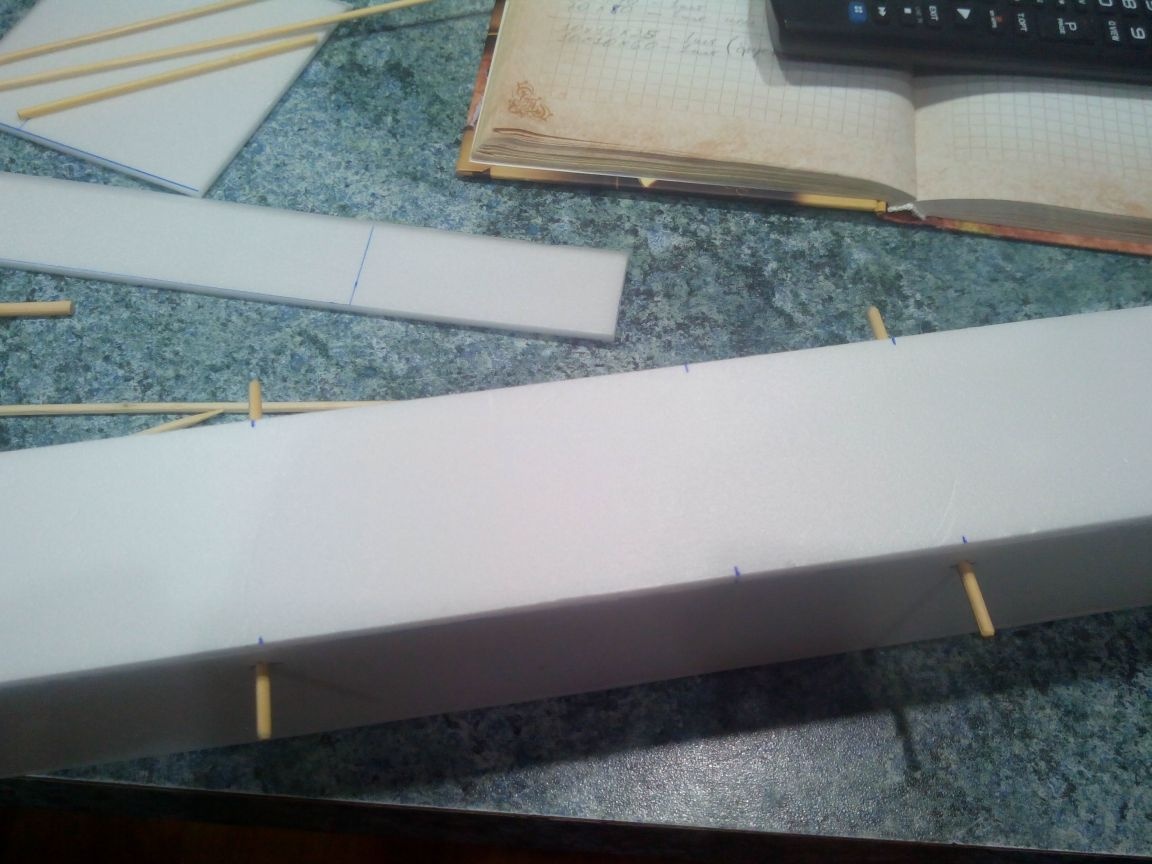
We insert the motor compartment with the rubber motor into the fuselage and find the center of gravity of the model by balancing it on a pencil, for example. We put a mark on the top of the fuselage and measure from it 5 cm forward and 10 back - these will be the places of the front and rear edges, respectively.
Under these marks, 1 cm from the edge, we make holes with an awl, piercing the fuselage and the motor compartment through. We insert bamboo skewers into these holes (length 8-9 cm). It is not necessary to stick these skewers - they must be removed so that there is access to the rubber motor.
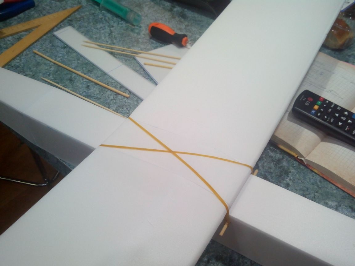
With two rubber bands for money we draw the wing to the fuselage.
There was the last touch - pasting the model with tape.
In order not to heavily burden the model, it is enough to glue over the center section, the front edge and the wingtips. So the wing will gain sufficient strength so as not to wrinkle from the elastic bands and withstand the planting model in the grass and bushes.
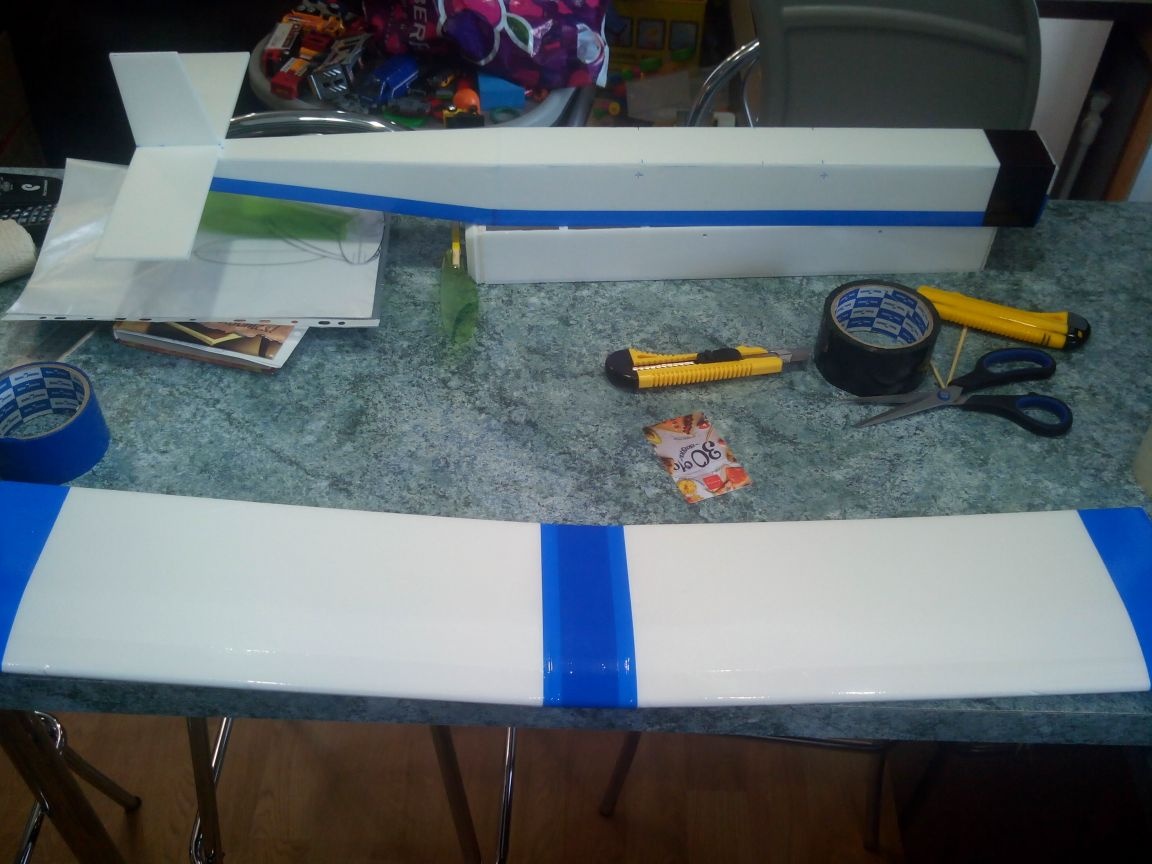
It is also not necessary to glue the entire fuselage with tape, it is enough to glue the bottom and nose.
The propeller blades and the nose of the engine compartment can be painted with markers.
A narrow strip of transparent adhesive tape can be glued to the front edge of the stabilizer so as not to damage it against grass during planting.
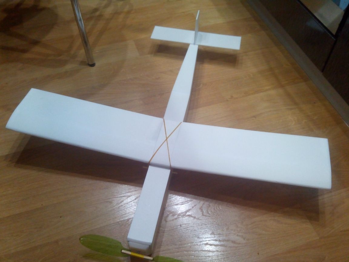
Everything, the model is ready!
A short video of the first flights of this airplane: