
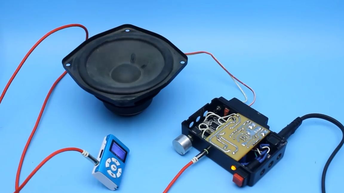
Most recently, the master literally for a penny bought a pair of speakers from a used system 5.1. He bought them solely because of their appearance. The owner offered the whole system, but alas, there was nowhere to put it. The speakers themselves are naturally passive. The power of each from a power of 7 watts. Inside there is only one dynamic head. Yes, and this is not the original Philips, but a Chinese clone.

The author stood these columns idle for about a week or two, after which he decided to make the most powerful power amplifier for them. Before starting, I set myself several tasks. In particular, the lowest possible cost of the project, the most compact dimensions and output power of about 10 watts per channel. Oh yes, and most importantly, it should be a full-fledged amplifier with a built-in network power supply.
I must say that all the points are fulfilled with a bang, well, at least the author thinks so. Let me remind you once again that this is the most cheap project, but despite this, the amplifier is quite listenable. But if you need something more and not homemade, then you can see what local shops or aliexpress offer. But this is not our choice, we are the inhabitants of our site.
Now let's talk about the components.
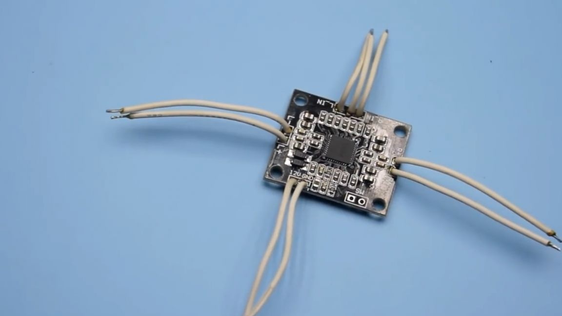
As an amplifier, a finished board based on the pam8610 microcircuit is taken.
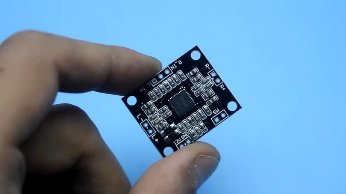
Such a board costs a little more than a dollar, and most importantly it works in class d, which means that the amplifier will practically not heat up. Therefore, there is absolutely no need for a radiator, and this, in turn, dramatically reduces the overall dimensions of the entire structure.
The amplifier is two-channel. Despite its rather modest size, it produces about 15 watts of power per channel. Such a circuit is powered from a source with a voltage of 12 V.
The power supply itself is pulsed. The board was specifically designed for this project.
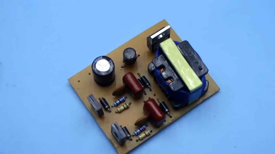
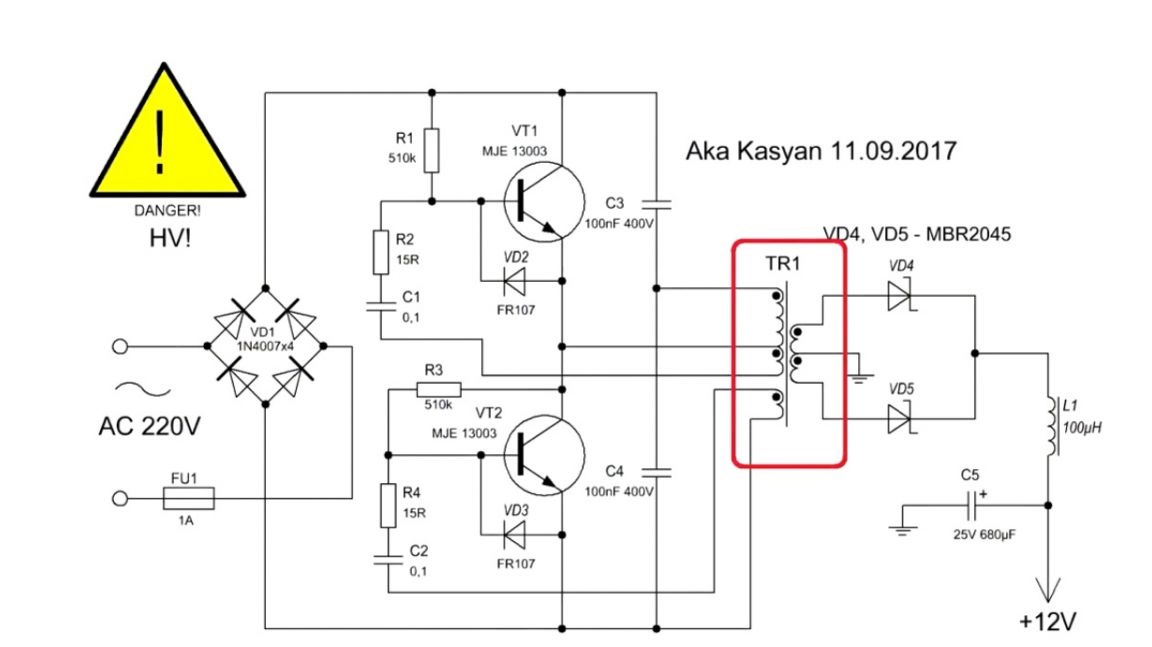
This is a half-bridge self-generating network switching power supply. The circuit is simple, no chips, just a couple of transistors. In essence, this electronic a transformer, but differs from classical circuits in that it starts without load, and according to the author, the device works a little more stable. How to collect exactly the same power source, what winding data and other details can be found in one of the author’s past videos. You will find a link to this video in the description under the video for this homemade product (link to the source at the end of the article).Further briefly on the manufacturing process of the power supply.
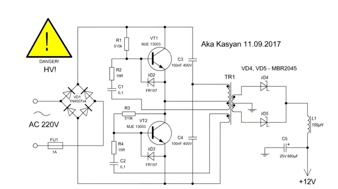
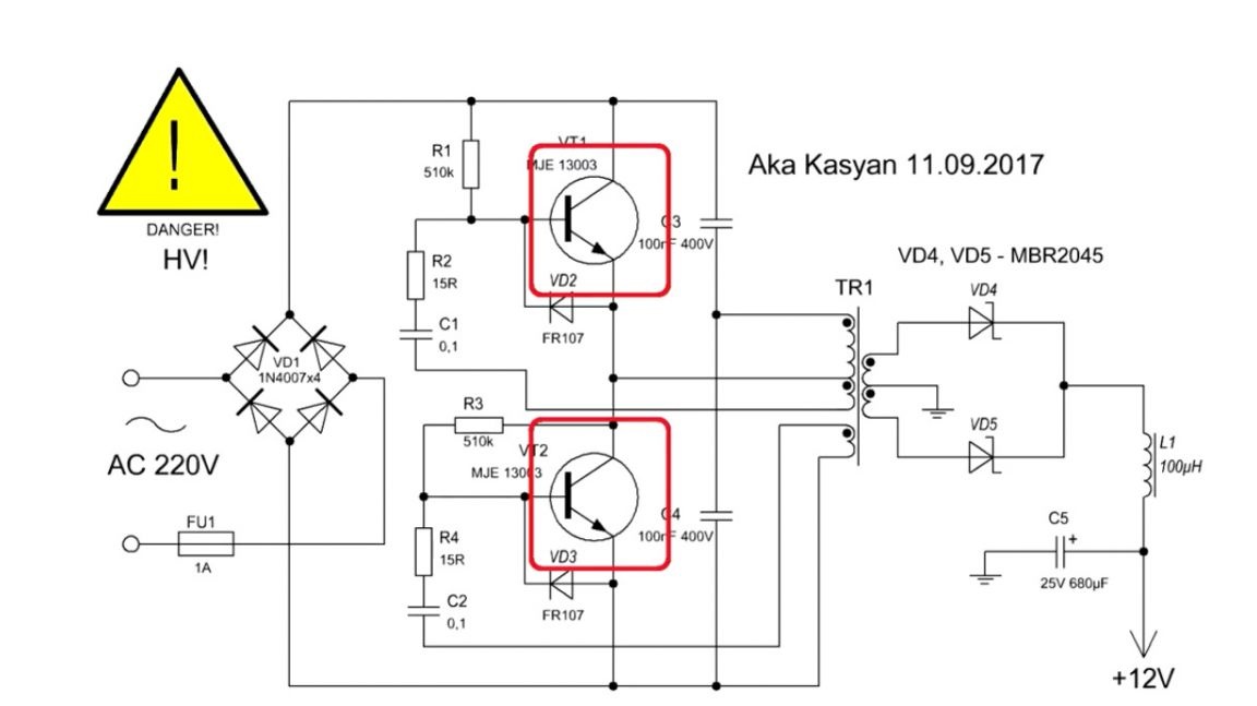
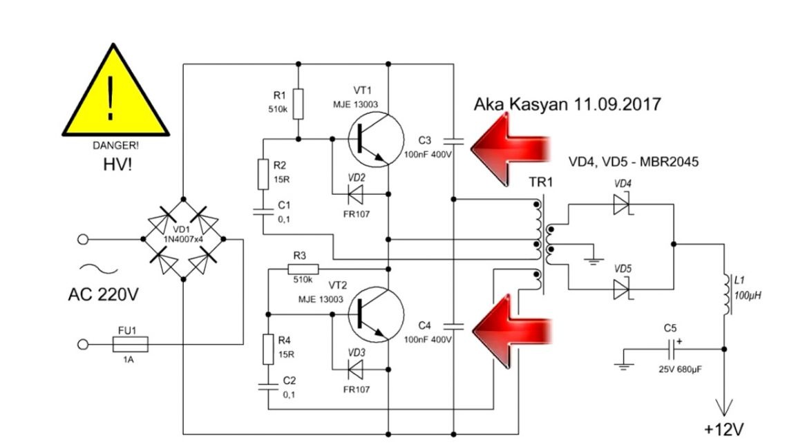
Now you are presented with a circuit that the author has copied from a rather rare electronic transformer. In this scheme, the base windings for the keys are wound on the main transformer, so there is only one transformer. There is also no dinistor. The presented scheme is painfully simple. The transformer does not need to be carefully calculated.
A few words about the components: 2 transistors from the MJE line (you can use MJE 13001, 13003,13005 more powerful ones do not make sense); half-bridge capacitors should be rated for 250 V, and preferably 400 V. At the output we have a half-bridge rectifier (a double Schottky diode MBR 2045CT is used).
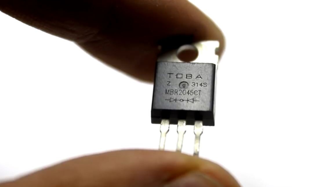
Such a diode has a multiple current margin. You can use diodes for a couple of amperes, but our option is easier to find, if you have at hand, an inoperative computer power supply.
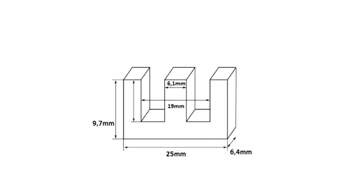
Throttle. Its inductance is about 100 μH, the diameter of the winding wire is 0.65 mm. The parameters of this throttle are not particularly critical. During preliminary tests, the author used a choke, whose inductance differed by 50%, and they all worked fine. Pulse transformer is the most difficult part in this circuit. The dimensions of the core used by the author are presented below.
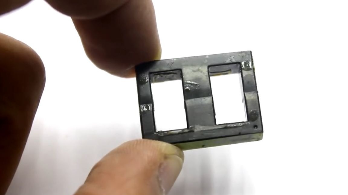
Since the circuit is push-pull, the core halves should not have any clearance. It is very important to remember and follow the winding sequence of the windings. First, a primary or network winding is wound on a bare frame. It is wound with a 0.3 mm wire and contains 130-140 turns. The winding is wound in layers, it is desirable to isolate each layer. Next, one of the basic windings is wound. It contains 5 turns and is wound with the same wire as the network winding. Insulation is placed on top of this winding, and a second winding is wound. It is identical to the first and contains 5 turns of 0.3 mm wire.
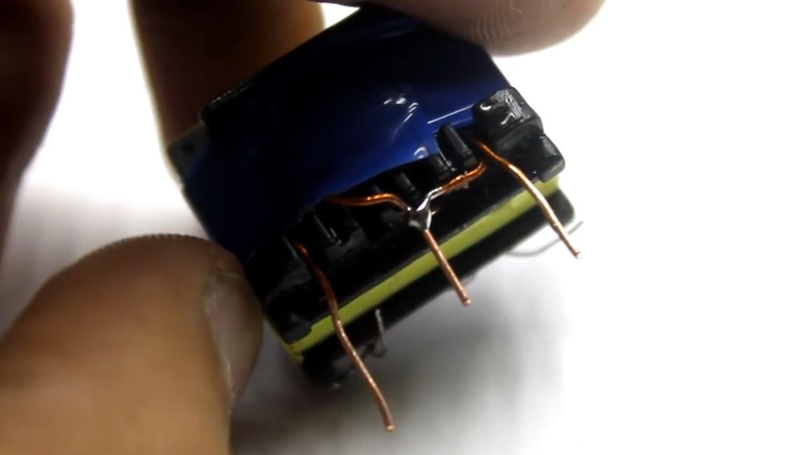
Then we wind the secondary winding. This winding is wound at the rate of 1 turn - 1 volt. In this case, the winding contains 2 to 12 turns with a wire of 0.8 mm. After winding, the beginning of the first shoulder is connected to the end of the second, for the formation of a midpoint, according to the scheme we have this mass.
The presented circuit does not have protection against short circuits, therefore, in no case do not short-circuit the output and never touch the board during operation. The cost of building such a power supply is minimal. All components can be found in old computer power supplies, in ballasts, economy lamps, and so on.
Such a power supply can give a load of 30-50 W with this arrangement of components. The output voltage is 12 volts.
Let's start the build.
The first step is to prepare the wires. The author, for this homemade product, used these ones:

The wires must be cleaned and tin-coated accordingly. Then solder to all inputs and outputs of the audio amplifier, as well as to the power supply contacts. It looks like this:
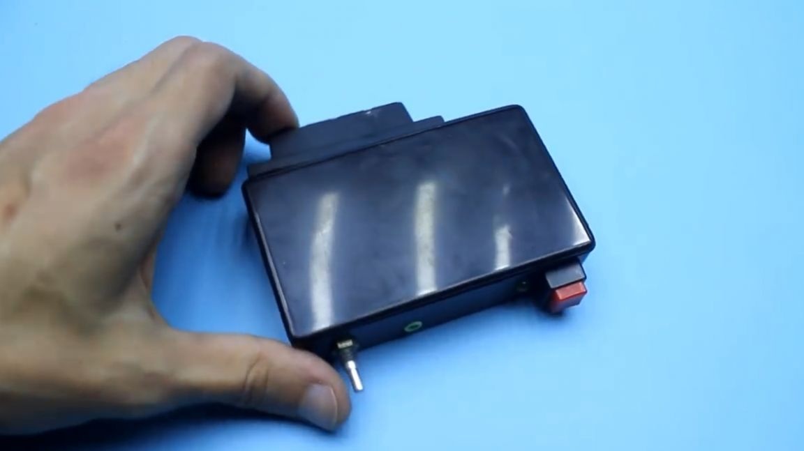
Further, under this whole thing, we need an appropriate building. Since the board of the audio signal amplifier has rather small dimensions, and almost all components of this homemade product do not have any impressive dimensions, a very small plastic box will be suitable as the body of the future audio amplifier.

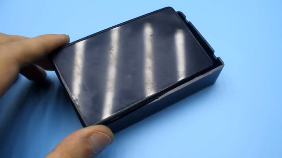

In such a case, I think, all the components of our home-made device will fit freely.
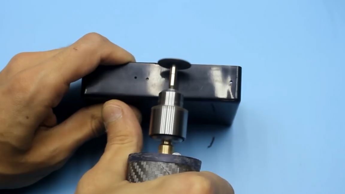
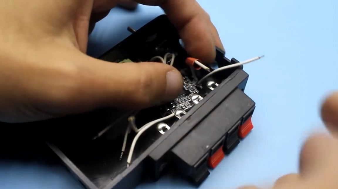
Then we will install the speaker column (4-pin) in the plastic case of the future product.


To do this, cut a hole in the housing. The author first, using a screwdriver, drills small holes, and then, with a drill with the appropriate nozzle, cuts a rectangular hole in the body, the required size for installing the column jack.
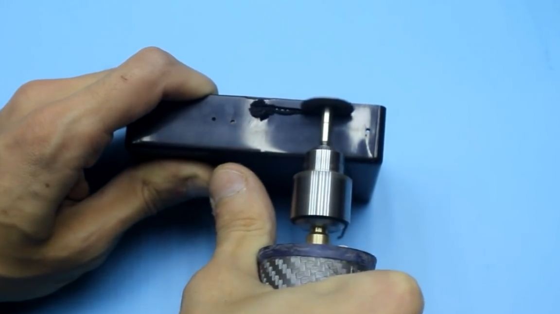

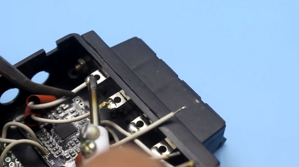
Column nest in place. You can immediately irradiate contacts.
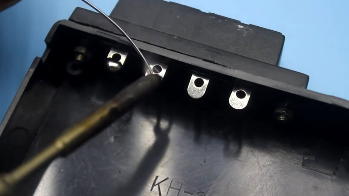
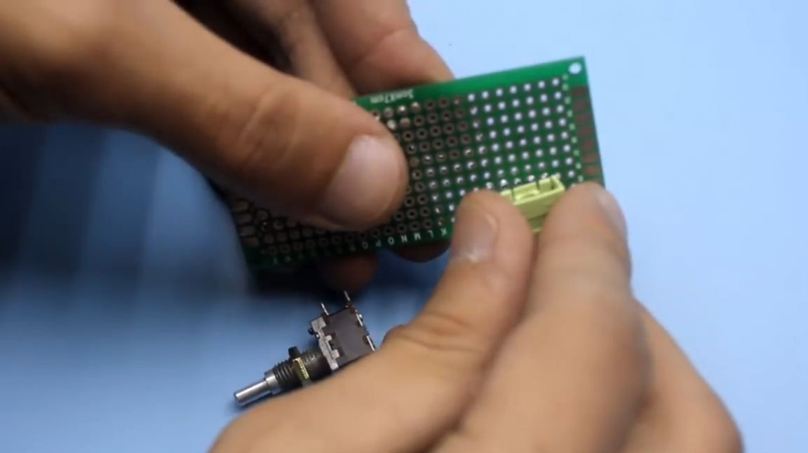
Next, set the volume control and the input for a mini jack 3.5 mm.
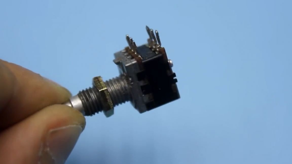
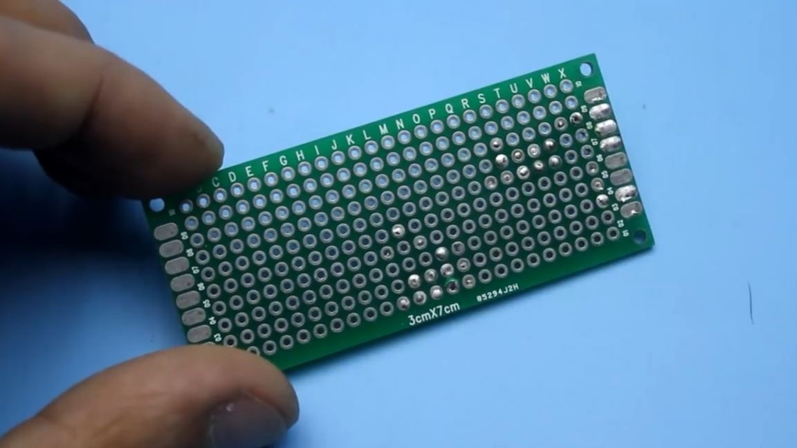
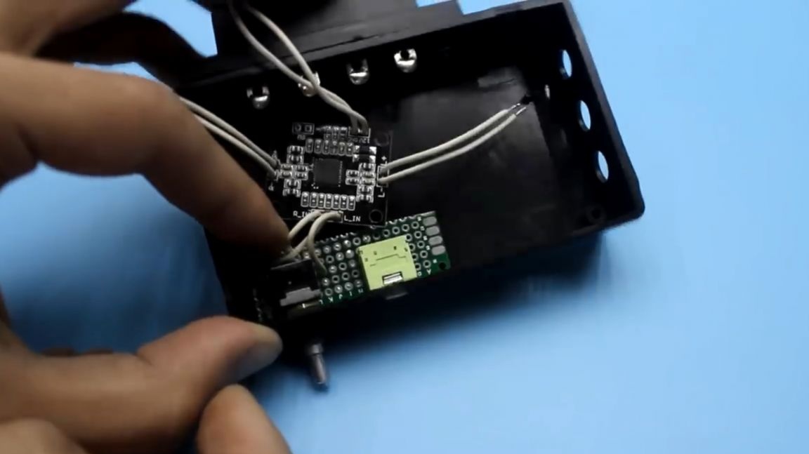
The author placed these components on a breadboard printed circuit board and soldered.
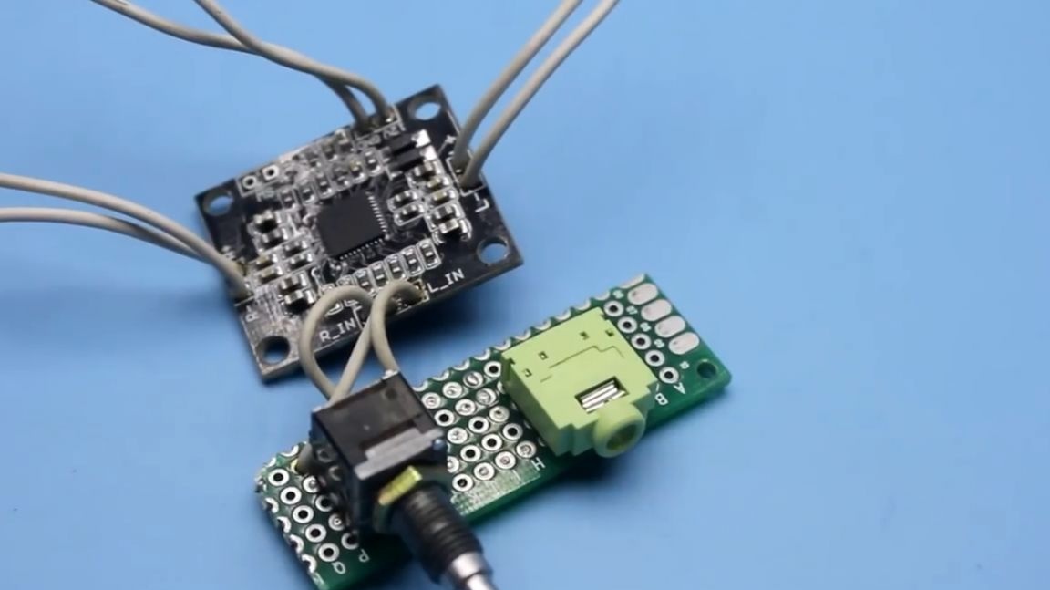
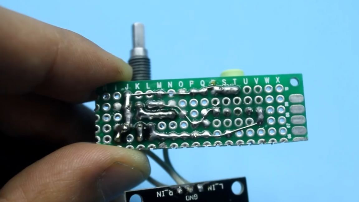
Now let's install the pam8610 audio amplifier and a breadboard with a volume control and audio input into the case. To do this, 2 holes must be made in the plastic case.

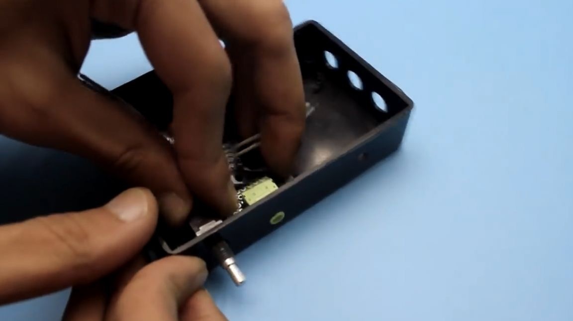
Then we cut the required amount, as well as the required length, of the heat shrink tube.

We put pieces of heat shrink on the wires coming from the pam8610 chip. Then we solder the wires to the previously tinned contacts of the column socket and isolate the joints with a heat shrink tube.
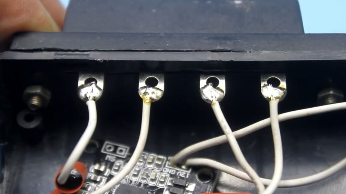
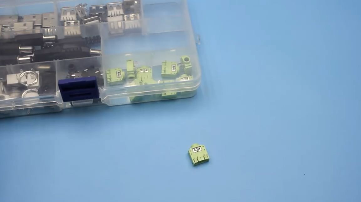
Next, you need to determine the location of the socket for connecting power.
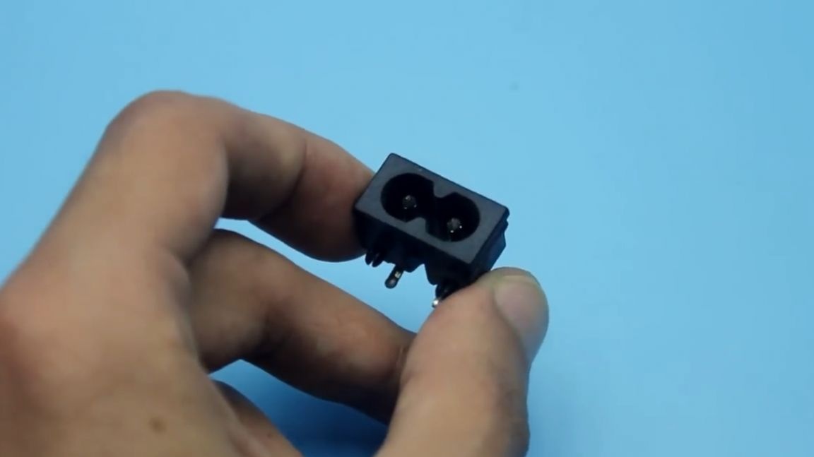
When we have decided on the placement, we cut out a place under the connector in the side of the case.
Then, using hot-melt adhesive, we fix the connector on the wall of the housing.


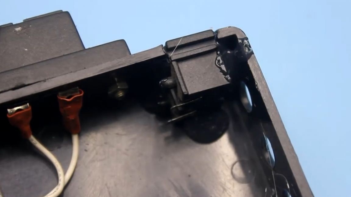
Then we will place the power on / off button on the side of the case. We also turn on the LED (the author chose a yellow LED), which will be an indicator.
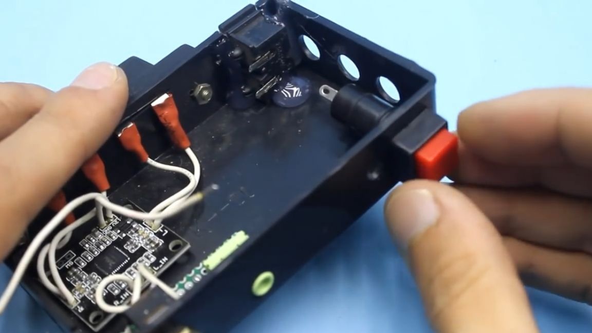
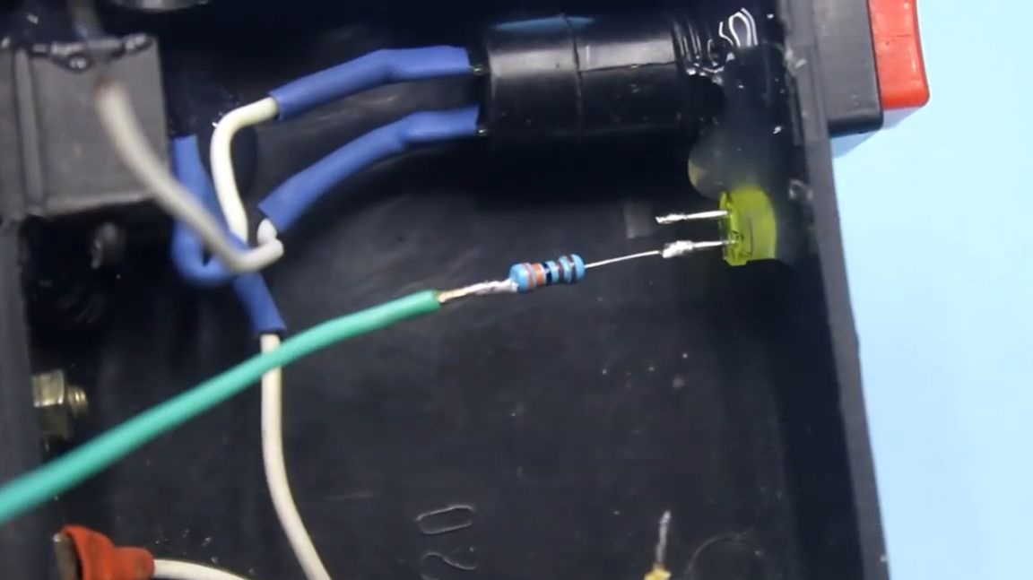
If the LED emits light, therefore, the device is turned on and working. It is unforgettable to pick up and solder the corresponding current-limiting resistor to the LED cathode. We isolate the joints by a heat shrink tube.
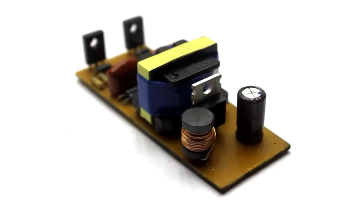
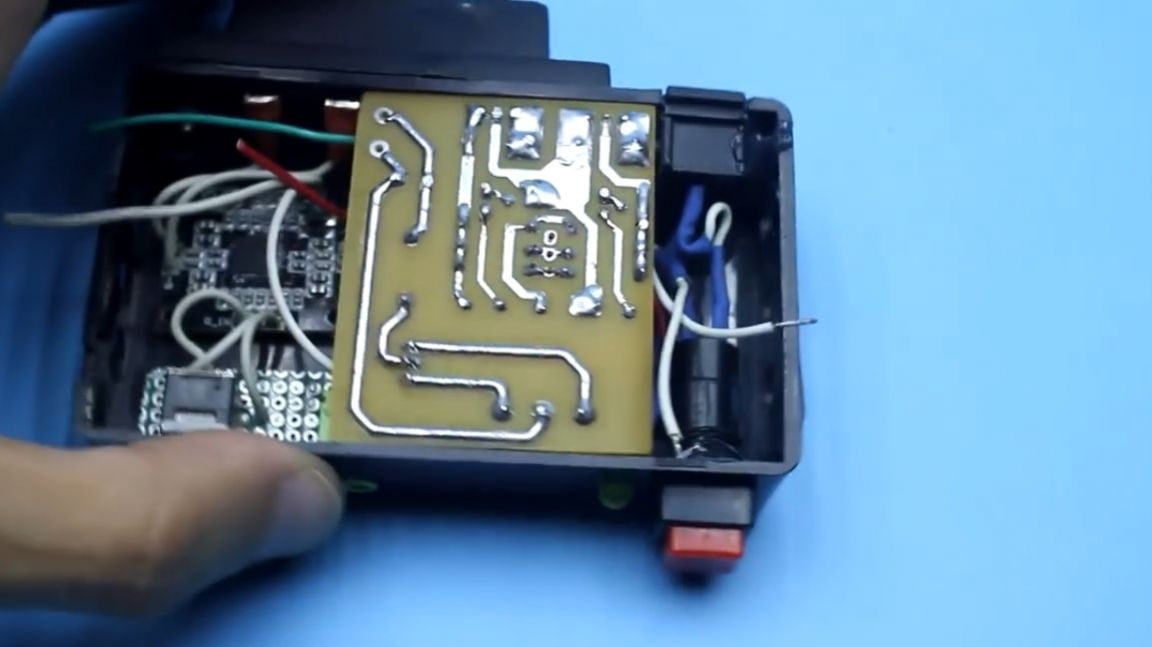
Now it's time for the power supply. This is how it looks:
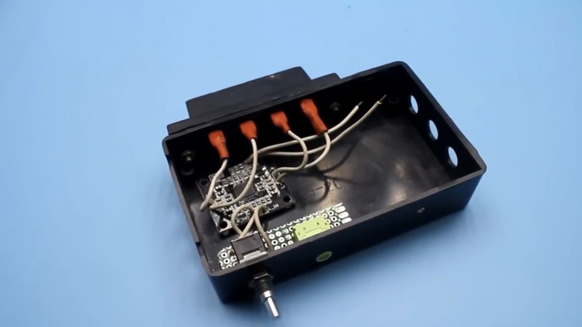
We place the power supply in a plastic case and solder the remaining wires.
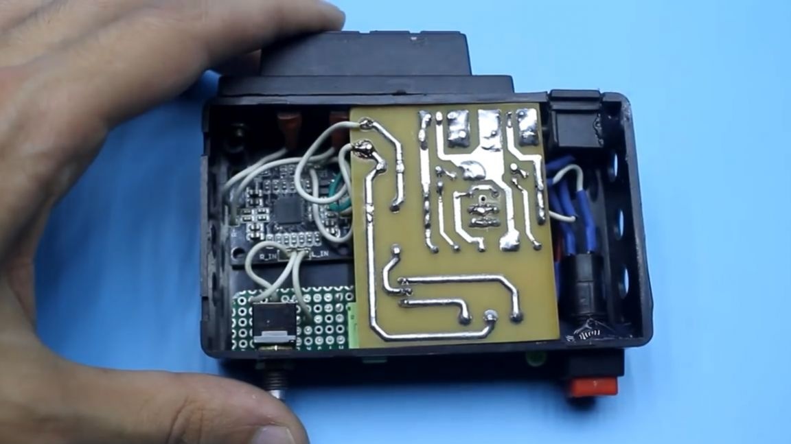
That's basically it. Homemade mini amplifier for speakers is ready. You can close the housing cover.

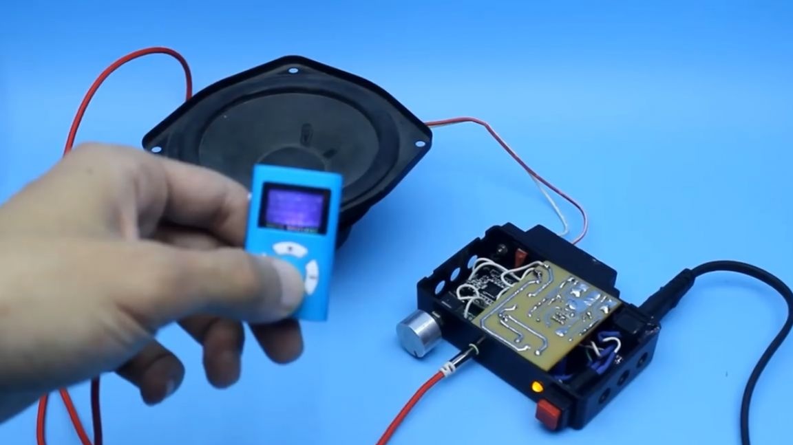
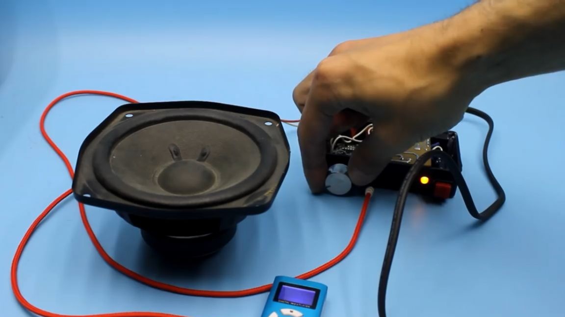
Thank you for attention. See you soon!
Video: