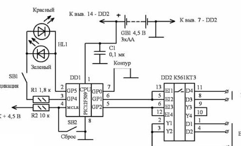
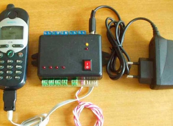
It will send a signal to your mobile phone when any sensor of the system is triggered. It works simply - the sensor acts on the auto redial button and a call comes to you. The circuit is based on the PIC12F509 controller and the K561KT3 chip.

The microcontroller controls the DD1 IC keys that control the power button of the phone and the call button. The SB1 button turns on the indicator, green indicates normal operation, red indicates system operation. To reset the settings, press SB2.
Construction and details:
1. PIC12F509
2. K561KT3
3. R1 1.8k
4. R2 10k
5. C1 0.1mk
6. Cr. Light-emitting diode
7. Green Light-emitting diode
The alarm is powered by three AA batteries, or one flat R12.
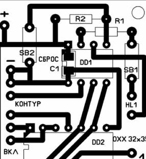
Board with elements installed on it

Before connecting the phone to the signaling, you need to put a dialer on your number on button 1. Turn off the sound greeting. We open the phone and solder to the buttons on. I1 wires 20 cm long. 3 from the button on And 2 from 1. We check the operation by closing the wires after resetting the SB2 button. Then we solder the wires and check the operation of the device.
And most importantly, charge the cell phone’s battery in time.
Microcontroller programming file and ohh.asm program:

