
I want to note that this article is likely to be more useful and interesting for car enthusiasts, since in this case we will consider an extremely simple, fairly low-cost and fairly reliable relay turn signal circuit.
As you know, basically there are two types of relays: electromechanical and solid state.
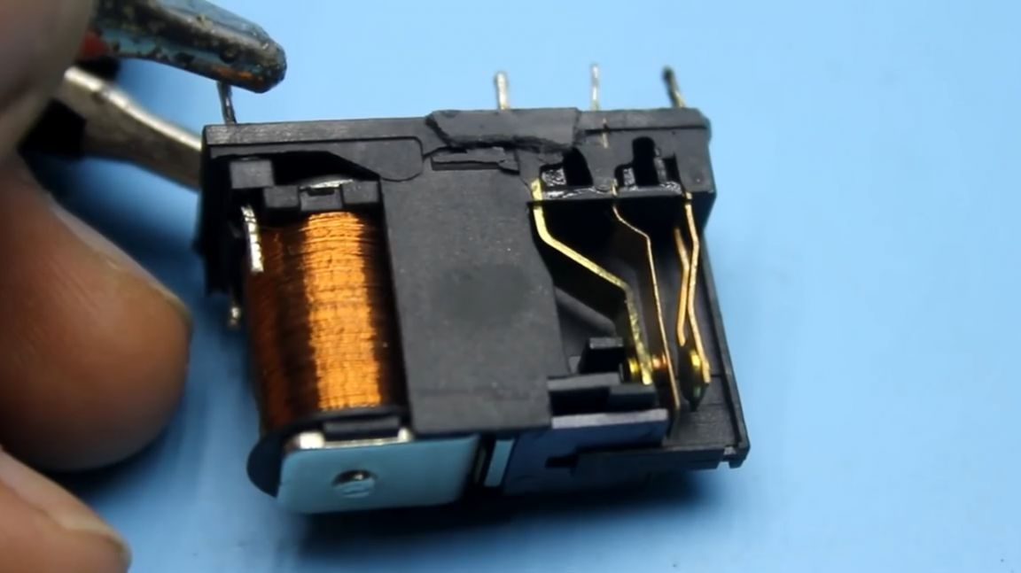
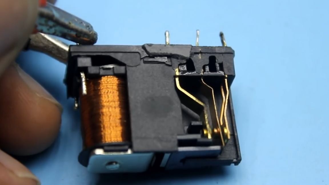
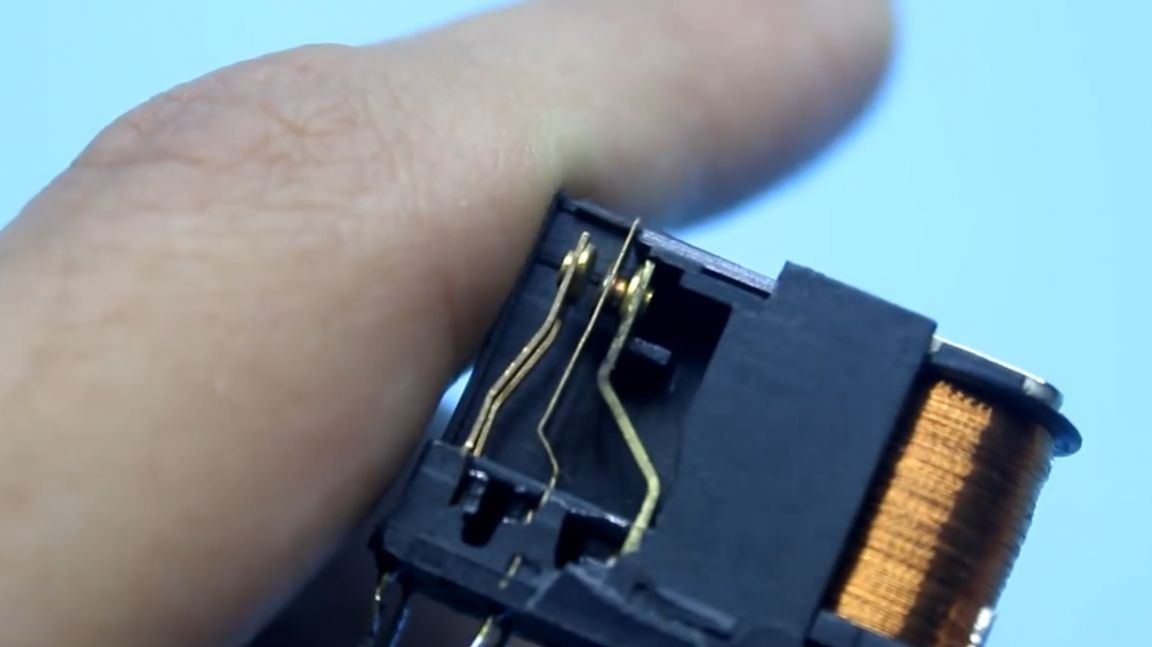
The most basic drawback of a conventional or electromechanical relay is that the contacts burn out over time. In addition, do not forget that their sticking is not excluded, even if the relay is new.
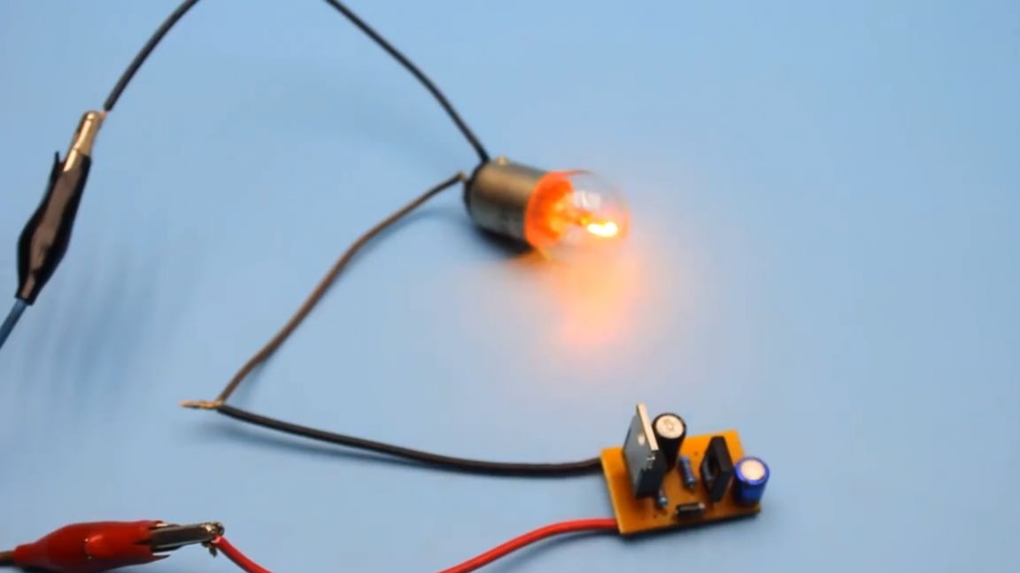
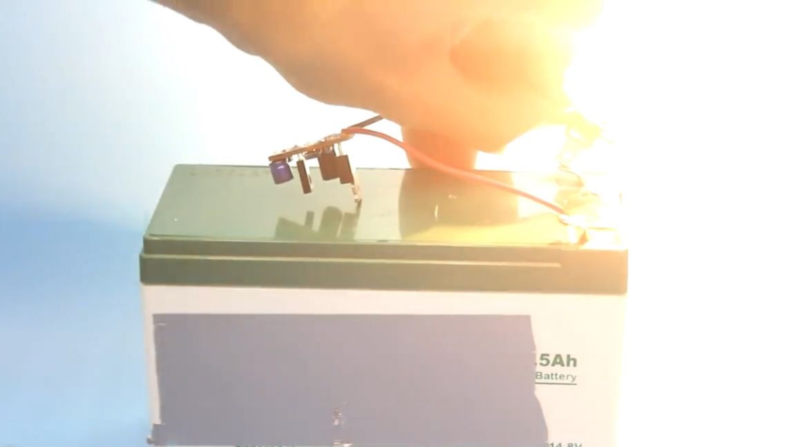
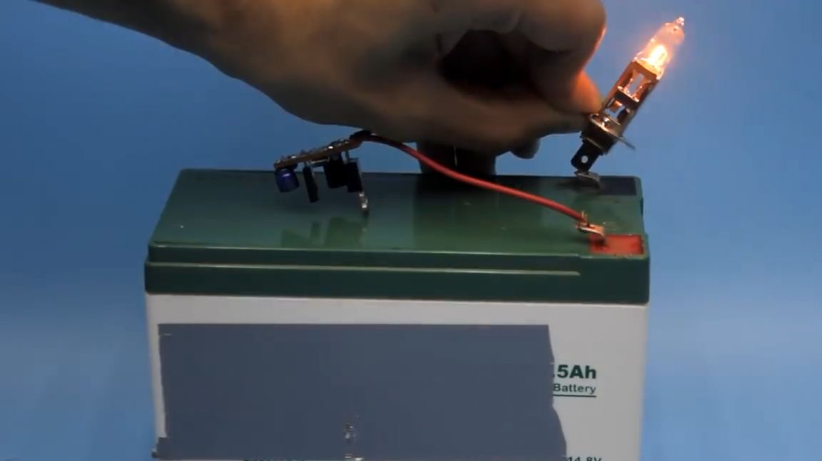
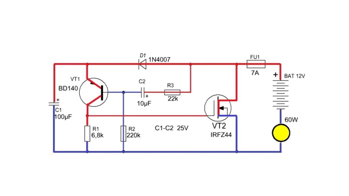
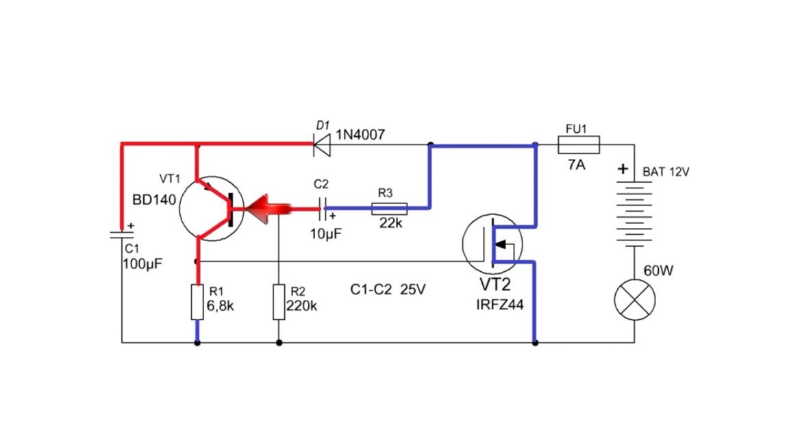
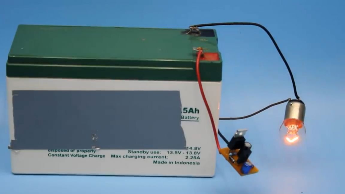
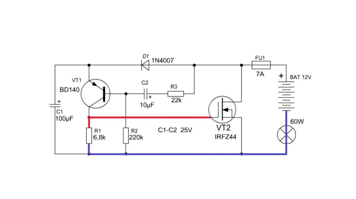
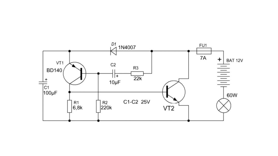
The presented circuit does not need additional configuration and will work immediately after inclusion in the circuit. And it connects to the power plus gap, or in other words, in series with the load. This is clearly demonstrated in the figure below:
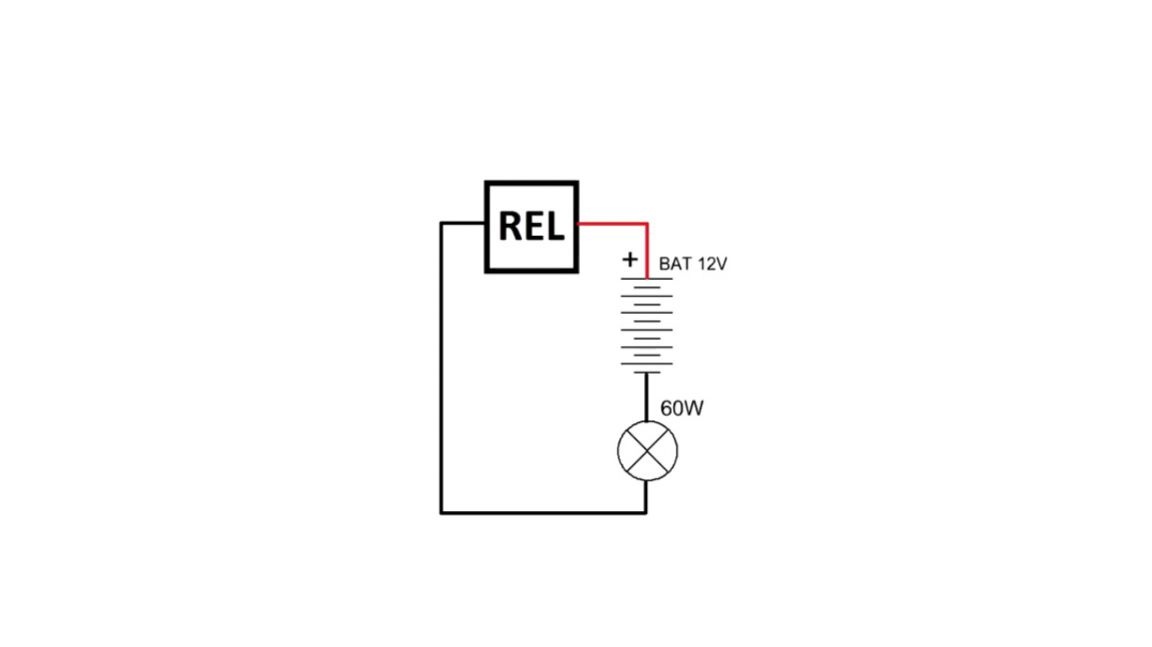
Such a scheme will work well forever, but it will cost much less than the finished version from the store.
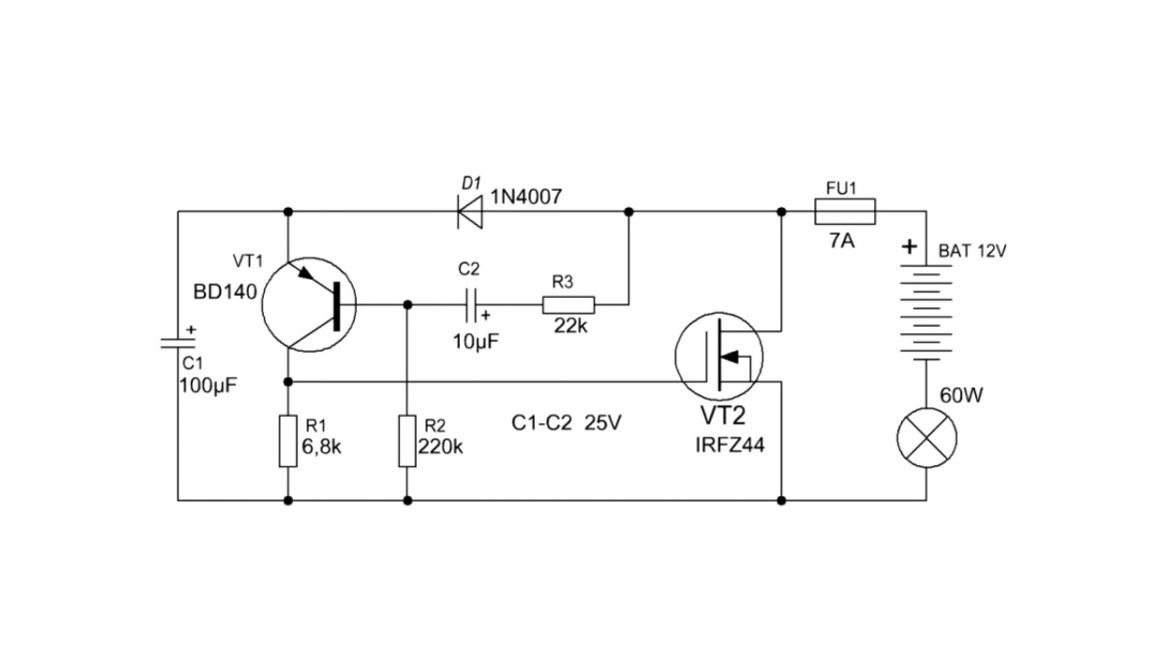
Now let's take a closer look at how this circuit works. In fact, this is an asymmetric multivibrator, slightly adapted for working with a field key. At the initial time, the capacitor c1 is charged through the diode d1, both transistors are closed.
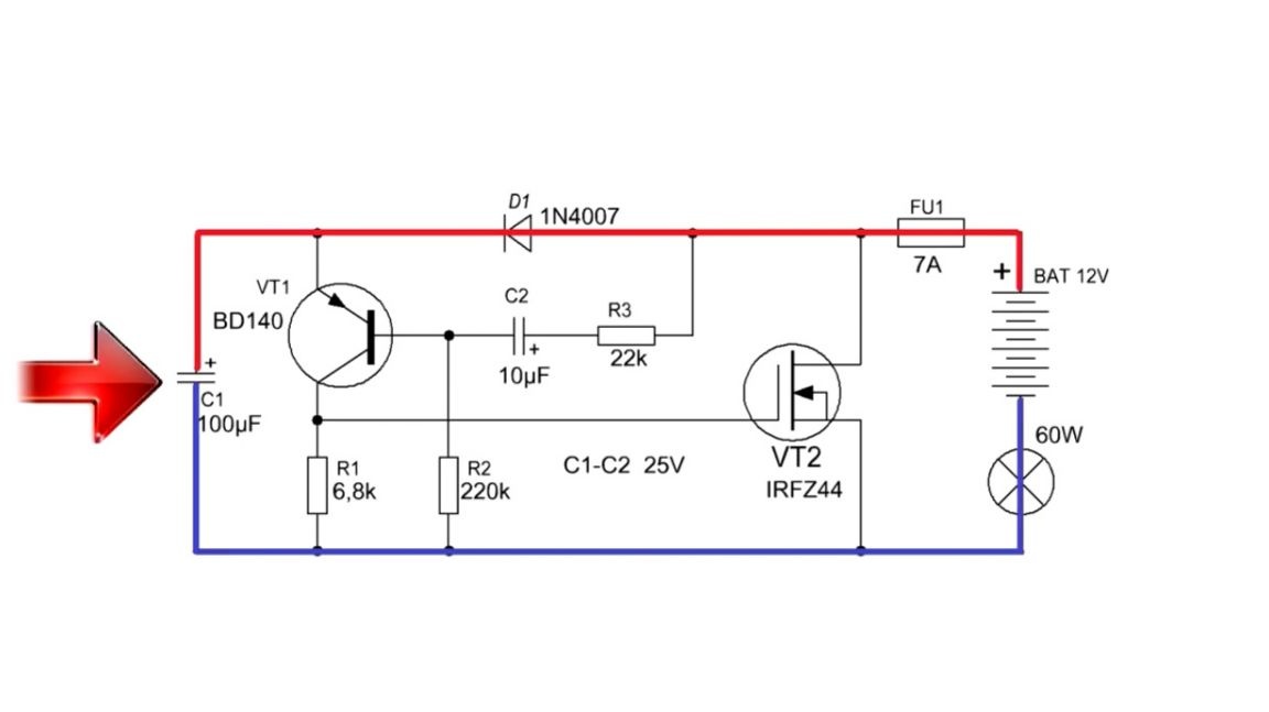
An electrolytic capacitor c2 is charged through a resistor r3.
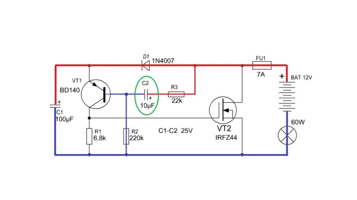
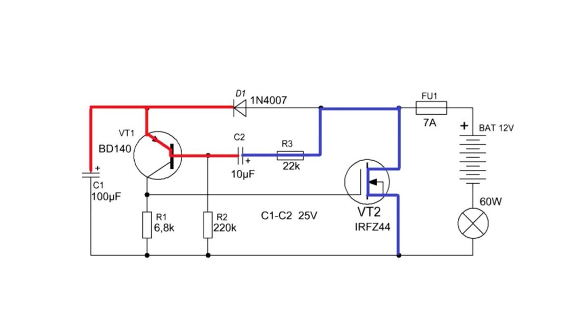
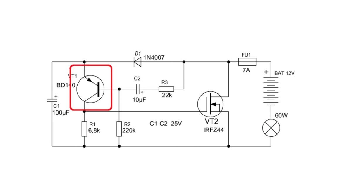
After some time, the voltage on this capacitor gradually increases to a certain value. And as soon as it is greater than the unlock voltage of the transistor vt1, the latter will work. Through its open transition, the voltage goes to the gate of the field-effect transistor, as a result of which it will instantly work, switching the load.
Roughly speaking, we use a field-effect transistor as a conventional switch, which is controlled by a generator circuit using a low-power transistor.
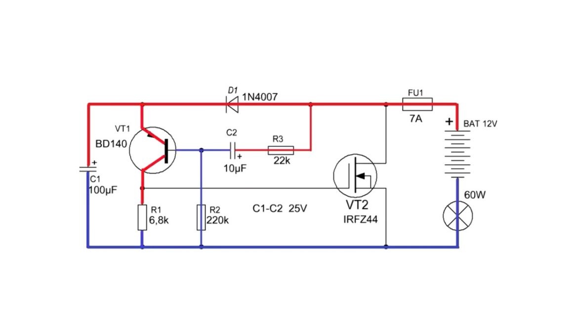
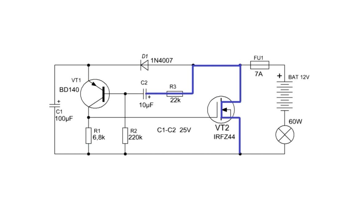
Further, after the key is triggered, the right side of the capacitor will be connected to the power supply, and the left, through the emitter junction of the first transistor, to the power plus. That is, the capacitor is charged with reverse polarity.

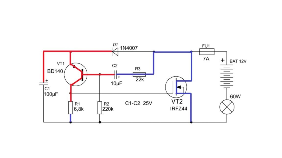
The charging current of the capacitor will keep both transistors in a saturated state.In this mode, the transistors are fully open and the efficiency of the circuit reaches its peak. As the voltage on the capacitor rises, the current of its charge will drop and the keys will accordingly exit the saturation mode, and in this state the power switch will already heat up.
Since the capacitor was charged with reverse polarity, roughly positive power will be applied to the base of the vt1 transistor, which leads to high-speed blocking of the transistor, and after that the field pole closes.
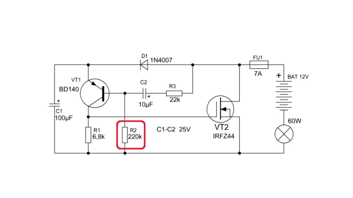
All this time, an insignificant current flowed through the resistor r2, which almost did not affect the operation of the ongoing processes.
If an explanation of the work of this simple scheme has forced you to brains, you will forgive.
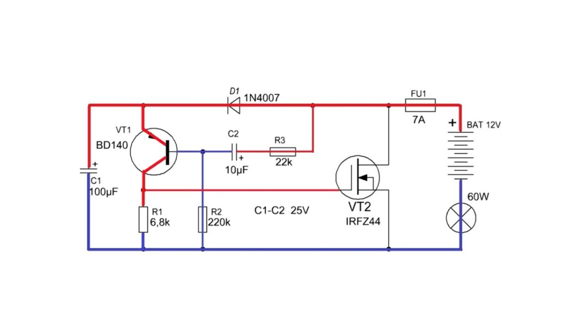
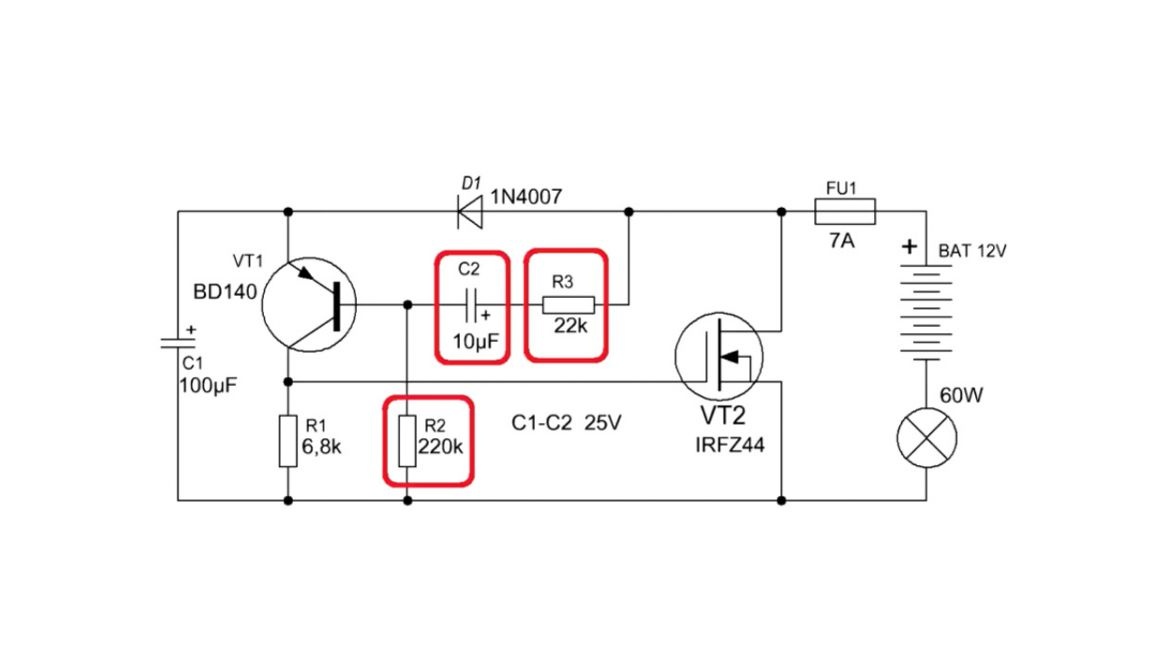
The response time of the field effect transistor, and therefore the flashing of the lamps, depends on the values of the capacitor c2 and the resistors r2 and r3. The larger the capacitance or resistance of the resistors, the lower the frequency of flashing. And vice versa, the lower the nominal value of the resistors r2 and r3, as well as the capacitor c2, the correspondingly the higher the blink rate of the turn signals.
Resistor r1 performs several functions. One of them is providing reliable locking of the field key.
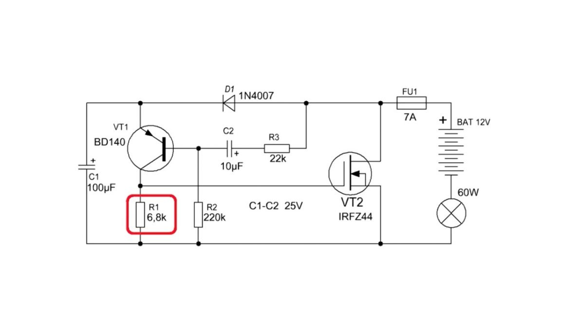
The transistor in the generator circuit can be taken of any average power, like bd140.

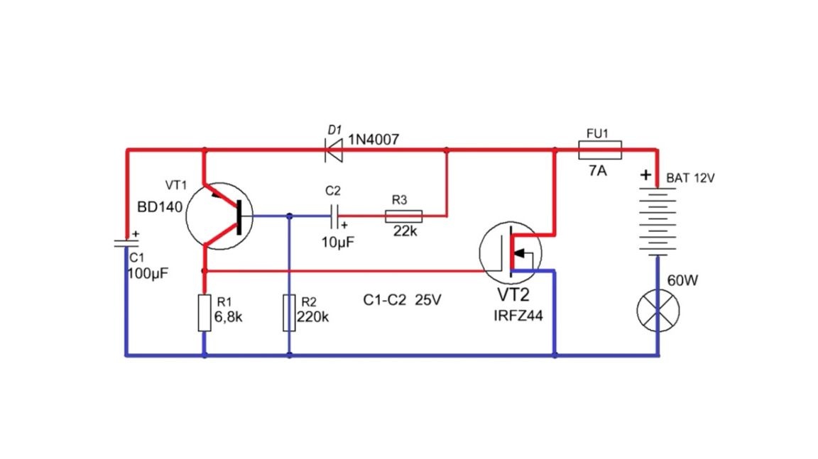
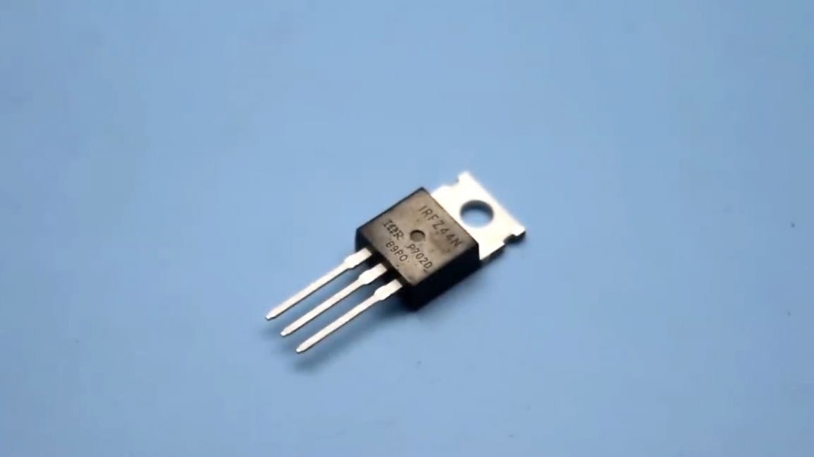
The choice of a field effect transistor depends on the power of the switched load. Transistors from old / non-working motherboards of a stationary personal computer are great for these purposes. In this case, the author put irfz44, as the most popular option.
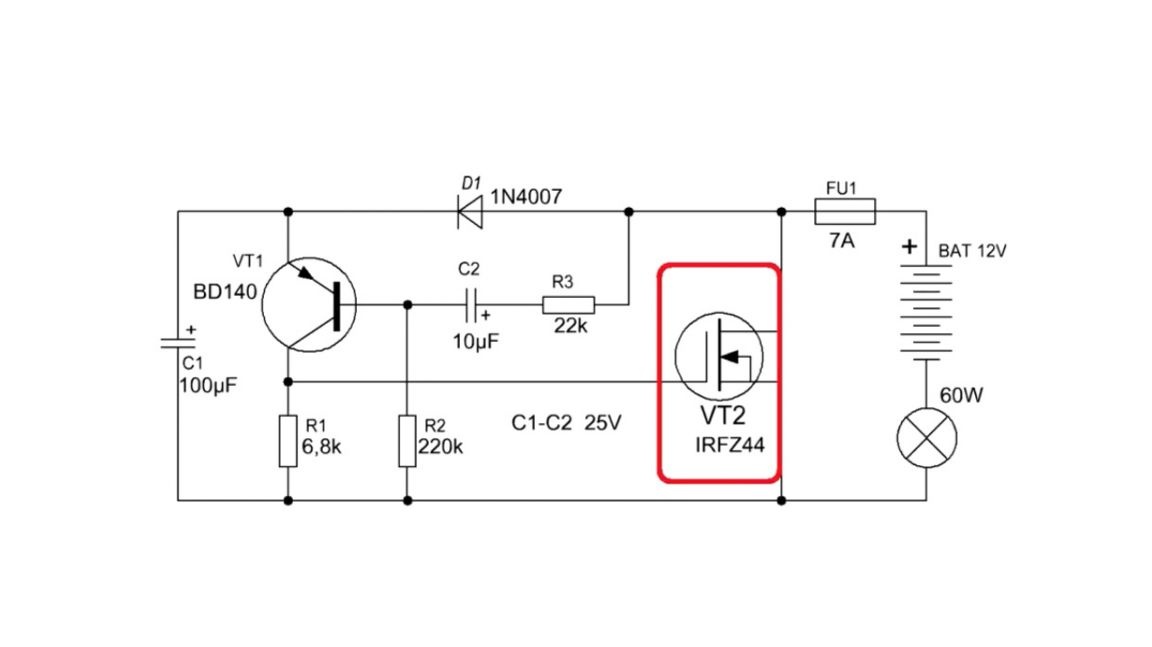
With this arrangement, the circuit can switch loads with a power of up to 100-150 watts, but most likely, a small radiator will need to be screwed to the transistor.
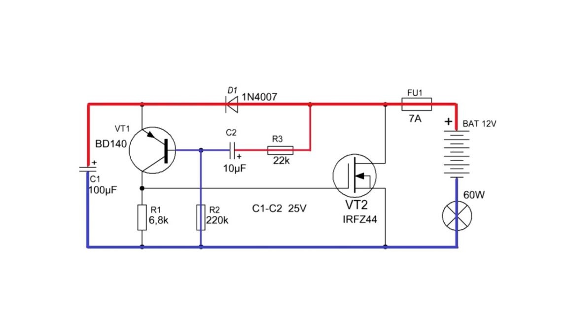
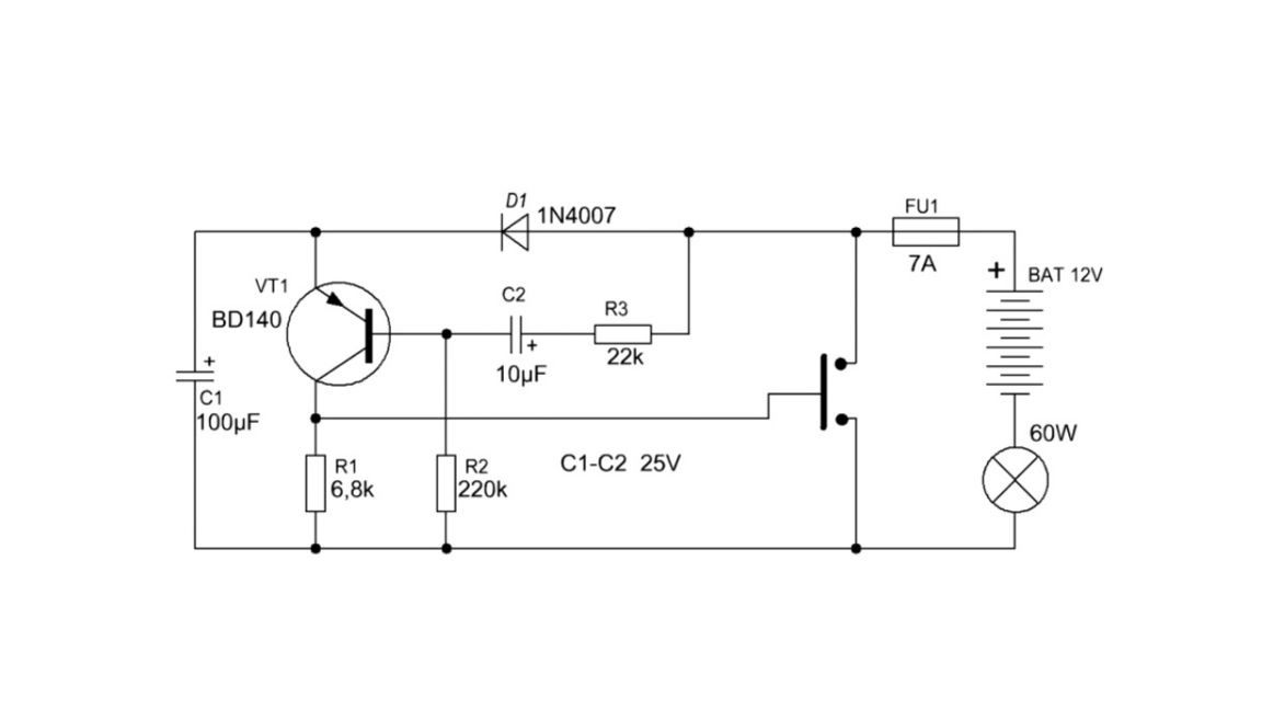
And with a power of about 50 watts, a radiator is not necessary. If the load is not very large, for example, an LED lamp, then a bipolar reverse transistor can be used instead of a field effect transistor. In this case, the circuit will look like this:
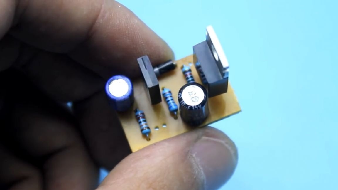
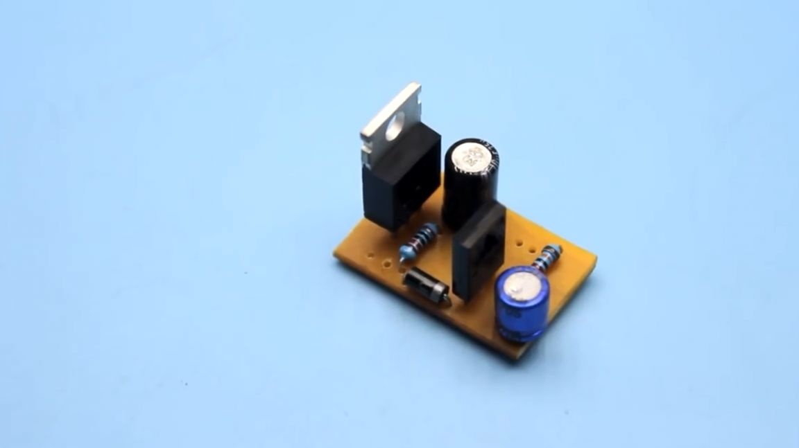
Just in case, the author spread the circuit board, although, in principle, everything can be assembled on the layout.


You can find a link to the board in the description under the original video of the author of the project. Link to the video below.
Thank you for attention. See you soon!
Video: