Watching the constantly arising energy in the nature around us (wind, sunlight, water energy), there is a desire to try to use this free energy. Of course, living among the mainland and in a temperate climate, the alternative energy that comes to us is small, we do not have coastal winds and a desert sun. Yes, the energy is not great, but it comes to us almost constantly. And if you make a device for its accumulation and use, do it yourself, from improvised materials, then this energy is free.
In some cases, you may need a small amount of electricity to power a low-power device. For the operation of a compact weather station, monitoring the water level in the tank, for emergency lighting and controlling the automation of the greenhouse. For each of these devices, you must have a power source. With periodic use of the device (for example, in the dark), it is advisable to use a battery-powered IP. Moreover, for its charging, it is most beneficial to use a renewable energy source, which will make the IP economical and autonomous. And when using wind and solar energy, the device, in addition, will be compact and mobile.
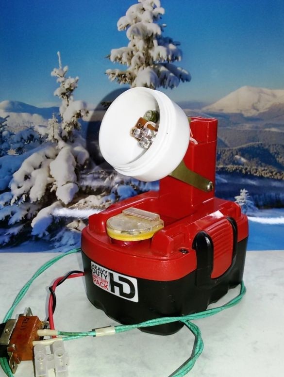
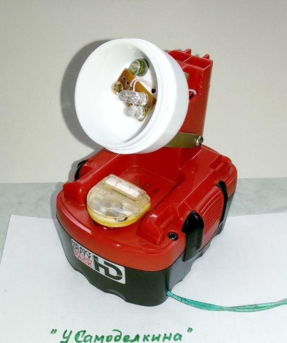
This article proposes to make a rechargeable LED lamp with charging from alternative natural sources of energy. Base for homemade served as a housing and reconditioned NiMH battery cells for a screwdriver, discussed in article.
Device diagram
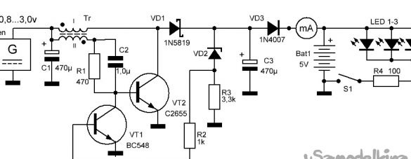
The circuit is a chain of an energy generator, energy converter, battery and light source. The energy converter is a stabilized voltage converter. It converts a low DC output voltage from a Gen source (wind generator or solar panel) to an increased voltage sufficient to charge a battery of four Bat1 NiMH batteries. The device is able to increase the input voltage from 0.8 ... 6.0 volts to the output 8 ... 30 volts. In this circuit, the output voltage is stabilized and does not exceed the maximum charge (1.8v x 4 = 7.2v).
Consider the operation of the converter.
The circuit is based on a blocking generator, consisting of a transformer, a transistor VT2, a resistor R1 (selected within 360 ... 1200 ohms) and a ceramic capacitor 0.33 ... 1.0 microfarads. During the operation of the blocking generator, due to the EMF of self-induction, which is developed by the primary winding, a high pulse voltage is generated at the transformer output. This voltage is rectified by the diode VD1, and then supplied to a rechargeable battery.
Stabilization of the output voltage of the converter.
Many rechargeable batteries cannot be recharged, as this shortens their service life. Therefore, in the considered circuit, stabilization of the output voltage is used. To do this, a VT1 type BC548 transistor, a Zener diode VD2 (stabilization voltage is selected), resistors R2, R3 are added to the circuit.
When the rectified output voltage from the blocking generator exceeds the stabilization voltage threshold, the zener diode begins to pass current through itself. This current flows to the base of transistor VT1. This transistor, in turn, begins to open and shunt the base-emitter transistor VT2 generator. This causes a decrease in the gain of this transistor, respectively, decreases the amplitude of the output signal.
Due to the fact that the NiMH battery has a significant capacity and can be charged with currents up to 1C, and the output current of the voltage converter is not high under normal conditions, the stabilization of the converter by current was not considered.
Manufacturing a voltage converter.
1. Details for the manufacture of the Converter.
The basis of the blocking generator is a transformer, which must be purchased or made with your own hands. Transformer design options are possible:
The primary winding of the transformer consists of 45 turns of wire with a diameter of 0.3 ... 0.5 mm, wound on a ferrite core with a diameter of 10 and a length of 50 mm. The secondary winding (feedback winding) consists of 15 ... 20 turns of the same wire wound over the primary winding.
The transformer is wound on a 2000NM ferrite ring of size K7x4x2 ... K12x7x5 and contains two windings of 20 ... 30 turns of PEV wire 0.3 ... 0.5.
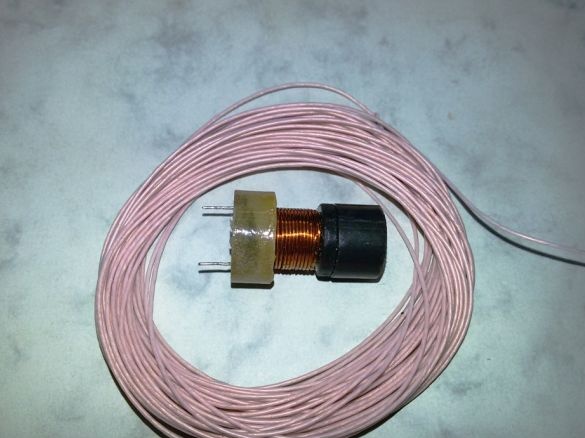
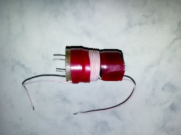
In our case, we’ll do it even easier. We take a ready-made inductor from 300 mH and above, over its winding we wind 20 ... 25 turns with a wire of 0.2 ... 0.5 mm, in the same direction. We connect the windings according to the scheme, taking into account the beginning of the winding (indicated by a dot). We fix the new winding with heat shrink, adhesive tape, glue. Such a transformer pumps no worse than a ring.
Transistor VT1 any low-power n-p-n type - KT315, BC548. Transistor VT2, n-p-n type, is selected depending on the load. The transistor VT2 does not need a cooling radiator, since the blocking generator operates in a pulsed mode.
It is advisable to use the VD1 diode from the “fast” series 1N4148, 1N5819 (Schottky), KD522 - suitable for current.
At the Zener diode VD2, the stabilization voltage is selected depending on the required output voltage. VD3 diode any suitable current.
Capacitor C1 smooths the fluctuations in the incoming voltage, and the capacitor C3 of the output voltage. The VD3 diode prevents the discharge of Bat1 batteries if there is not enough input voltage on it. The microammeter serves as a visual indicator of the charging current of the battery.
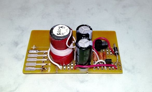
2. Assembly of the voltage converter.
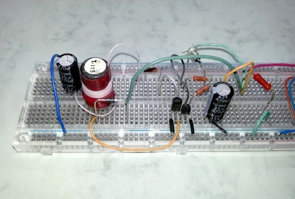
We complete the converter with parts according to the scheme. We assemble the converter parts on a universal circuit board. We connect the circuit to a regulated voltage source.
3. Configuring and debugging the operation of the converter.
We disconnect the Zener diode VD2 from the circuit, instead of R1 we set a tuning resistance of 4.7 kom. As the load of the converter, we install a 1kΩ resistor. By changing the resistance R1, we achieve the maximum voltage at the load. Without load, this circuit can produce 100 volts or more, so when debugging, it is advisable to set the output capacitor C3 to a voltage of at least 200V and do not forget to discharge it. Since the voltage amplitude at the output winding can be quite high, it is recommended to turn on the damping resistor with a resistance of 10 ... 100 k in series with the multimeter. It will help prevent damage to the device during measurements at various points in the circuit. To measure the constant voltage from the output of the rectifier diode, a capacitor with a capacity of up to 10 μF and a voltage of at least 250 V should be connected in parallel with the voltmeter. In this case, the voltmeter readings will be more accurate, since we will also measure the pulse voltage.
We measure the value of the optimal resistance of the variable resistor R1 and replace it in the circuit with the corresponding constant resistor. We install the Zener diode VD2 in the circuit, at the closest to the desired output, stabilization voltage. By selecting a zener diode, we achieve the required output voltage. This is the voltage we will use to charge the battery.
If the converter does not start, then we interchange the ends of one of the transformer windings.
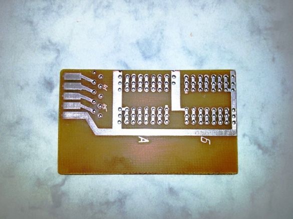
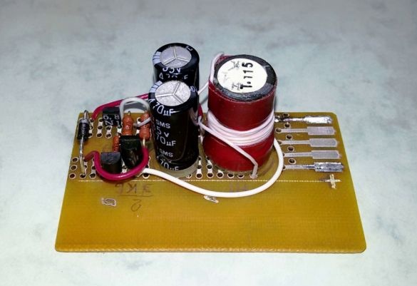
4. We prepare the blank for the working board by cutting out the desired size from a typical universal board. The dimensions of the working board are selected based on the dimensions of the proposed transducer housing and the place in it for installing the board.
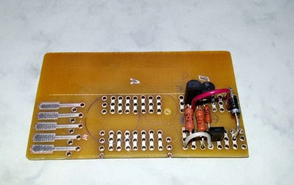
5. We carry out the wiring of the debugged circuit to the working board.
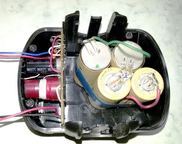
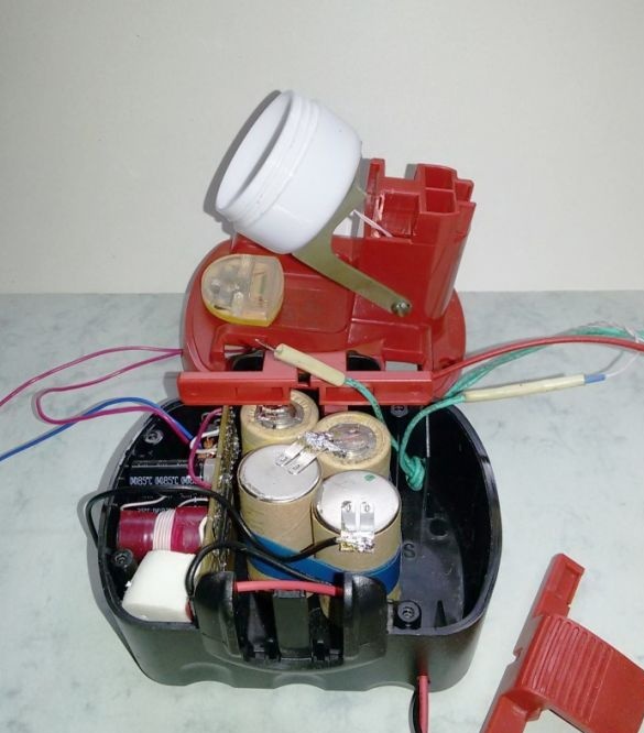
6. Install the converter board in the intended place of the base of the case from the NiMH battery for a screwdriver. We place a block of four restored elements of this battery in free space.
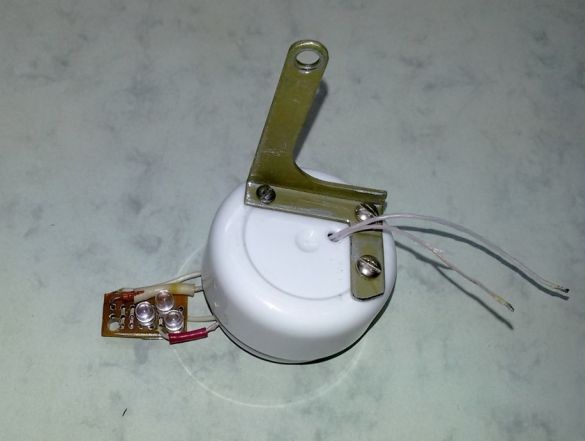
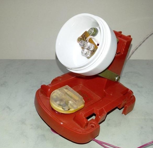
7. On a small PCB board we assemble a light source for the manufactured battery lamp. We solder on it a matrix of their three parallel-connected LEDs and limit resistance (see diagram). To fix the LEDs in the lamp, we drill a hole in the corner of the board.
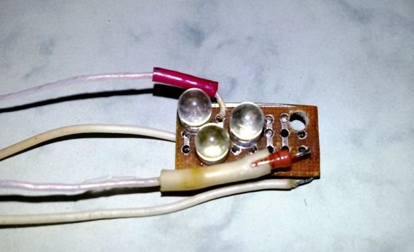
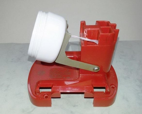
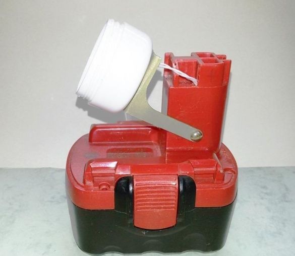
8. To accommodate the LED light source, we select a small plastic protective reflector case. We manufacture a transition metal bracket for adjustable installation of the reflector to the converter housing. We install and fix the LED board in place.
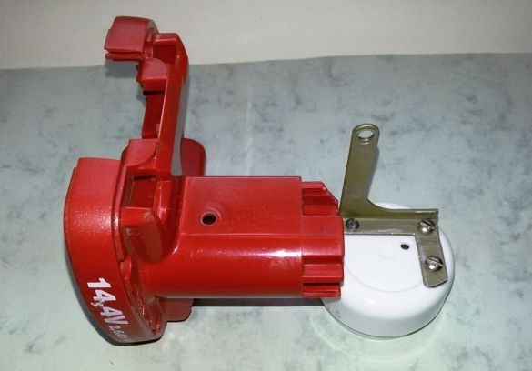
9. We assemble the upper part of the converter housing.
10. As a visual indicator of the presence and relative magnitude of the charging current of the battery, in the free space of the upper part of the converter housing, we place a microammeter - an indicator from an old tape recorder. The microammeter is designed for low current, so we calculate, select and connect a shunt resistor to the device to control the value of the expected battery charge current.
11. Connect the conductors to all parts in a single circuit.
We connect the converter board to the battery of the battery through the protective diode VD3 and a control microammeter. We bring out the connector for connecting the converter to an alternative energy source (wind generator or solar panels). We connect the LED light source to the battery through an external switch. Combine everything in a single building.
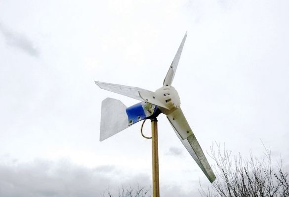
12. It is planned to use the manufactured rechargeable LED lamp, together with a wind generator based on a 24v / 0.7A permanent magnet permanent magnet motor. But that's another story.