
Hello to all lovers homemade. Many beginner hams collect radio designers that help to understand the principle of operation of individual components, capacitors, transistors and diodes. In this article I will tell you how to make a simple multivibrator based on a kit, which you can order on aliexpress at the link at the end of the article. This kit kit will help you in developing soldering skills, as well as concepts of what and how it works. Such a radio designer is often used in radio schools, and its advantage is that it is suitable for assembly even for beginners, there is nothing difficult to assemble.
Before proceeding to read the article, I suggest watching a video showing the assembly process and a small check of the finished kit.
To make a multivibrator-flasher do it yourself, you will need:
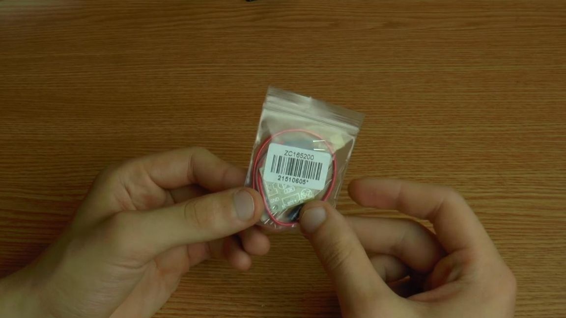
* Kit
* Soldering iron, solder, flux
* Side cutters
* Device for soldering "third hand"
* 3.7 volt battery
* Multimeter
Step one.
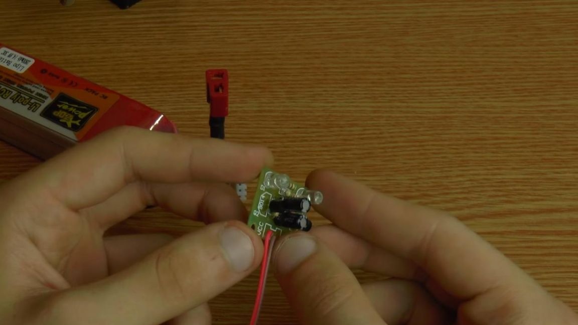
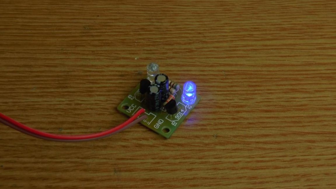
The kit of this kit kit is very modest, there are not very many details, just four resistors, two 9014 transistors, a couple of LEDs and polar capacitors and the printed circuit board itself, whose quality can be considered average, the tracks are made on one side.
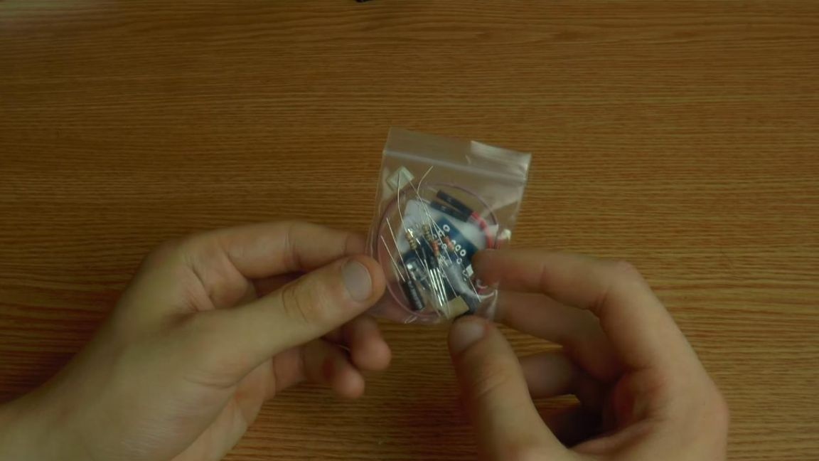
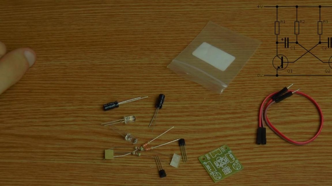
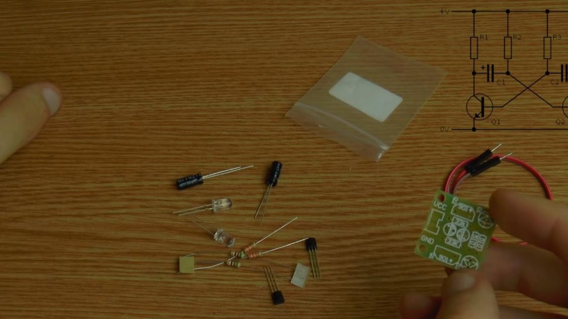
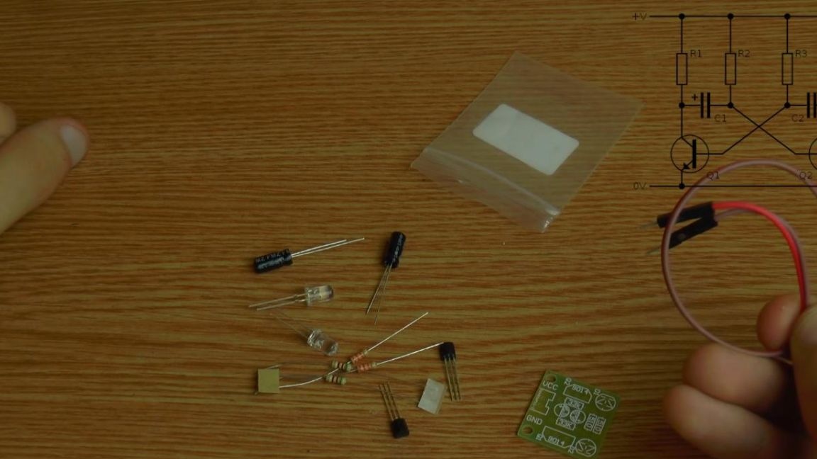
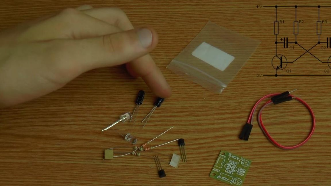
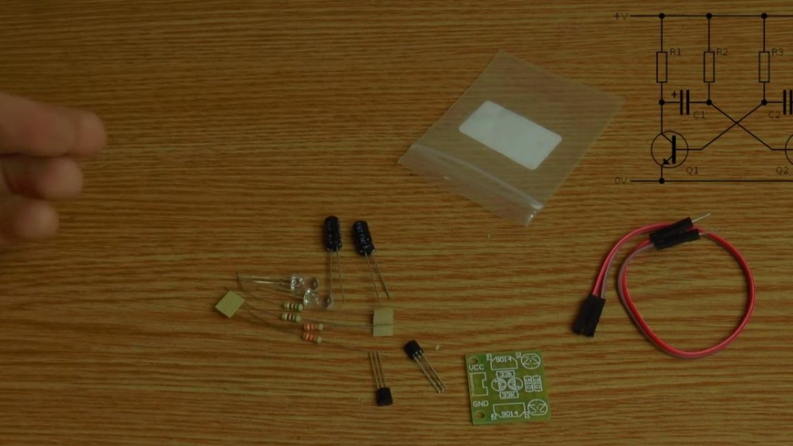
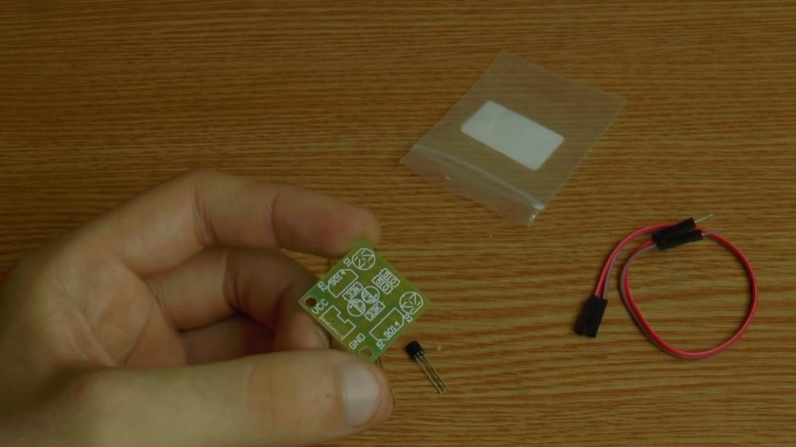
Also do not forget to put in the wires to connect the power. The number of components speaks for itself; assembly will be possible for everyone.
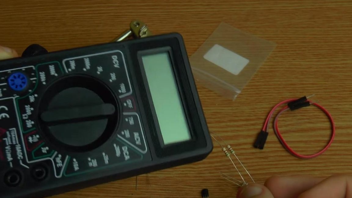
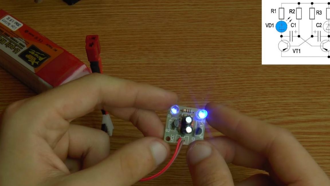
First you need to determine the values of the resistors, on the diagram we have four of them, and the values themselves are signed on the board. You can determine the resistance of the resistors using a multimeter, but if it is not there, then spending a little more time you can do this using the lookup table and the color coding on the resistor case, there are also sites with an online calculator in which you can simply enter the colors of the strips on the resistor and find out his resistance.
Step Two
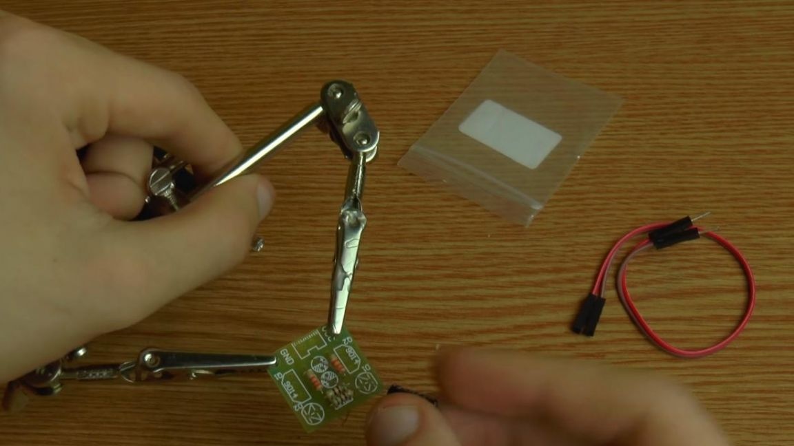
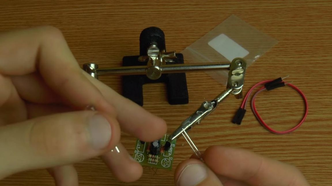
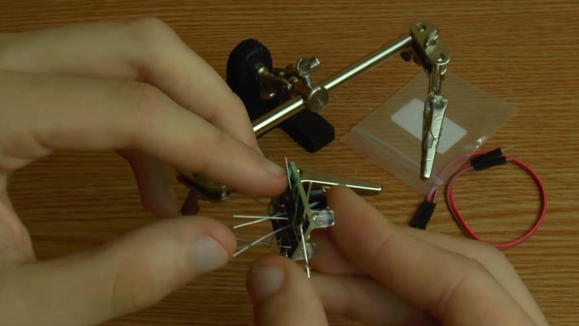
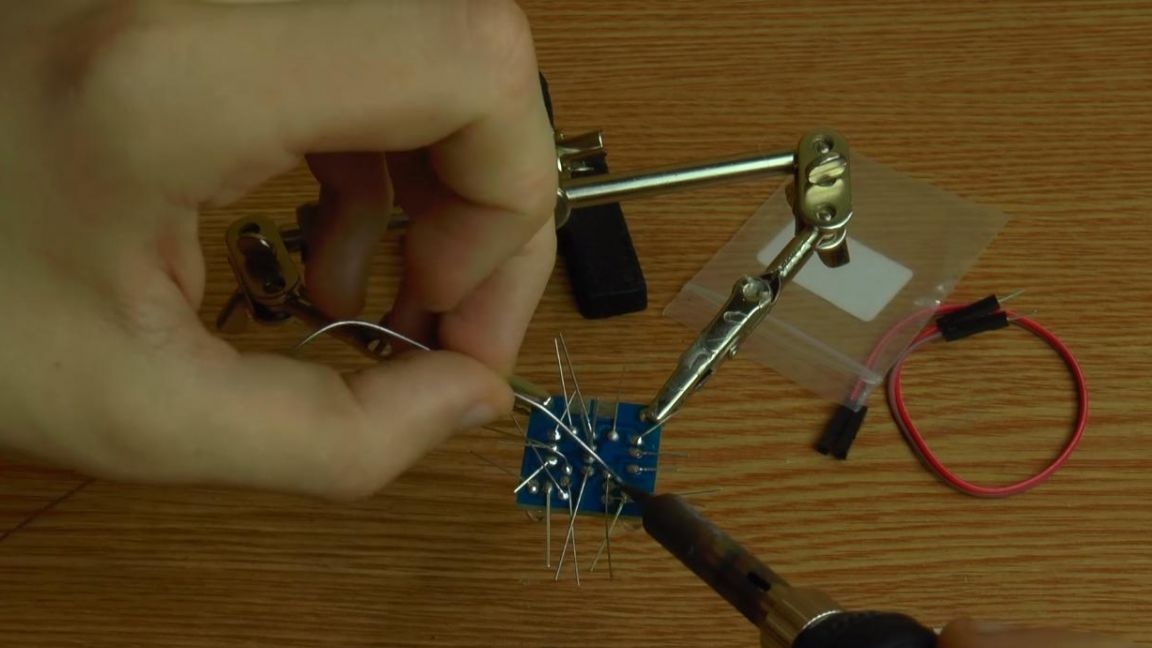
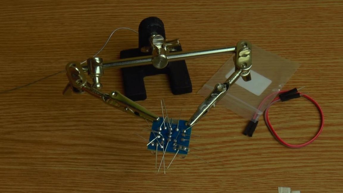
We fix the board in the "third hand" soldering device and install the resistors according to their nominal value.
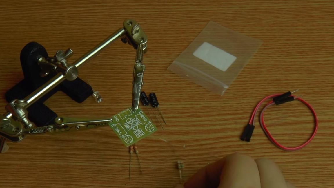
Next, we turn to the arrangement of polar capacitors, their values are the same, on the board there is a place indicated by a circle under them, the shaded semicircle corresponds to the negative output, and on the capacitor the minus is indicated by a gray strip.
You can also determine the polarity of the capacitor by the length of the terminals, long terminal plus, short minus.
Step Three
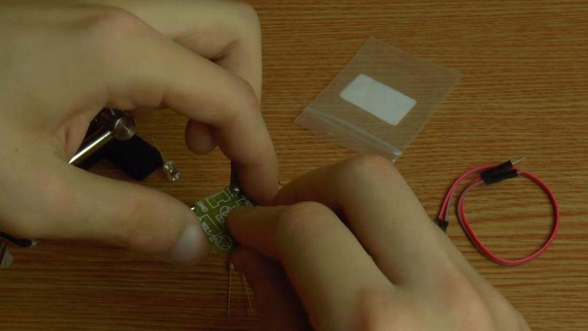
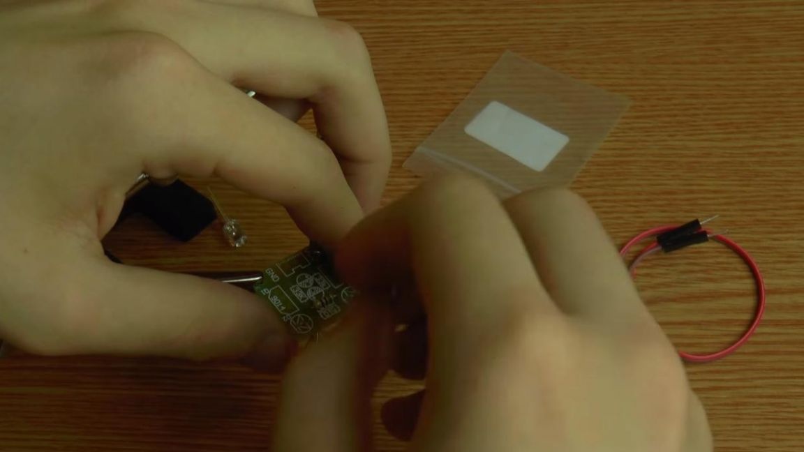
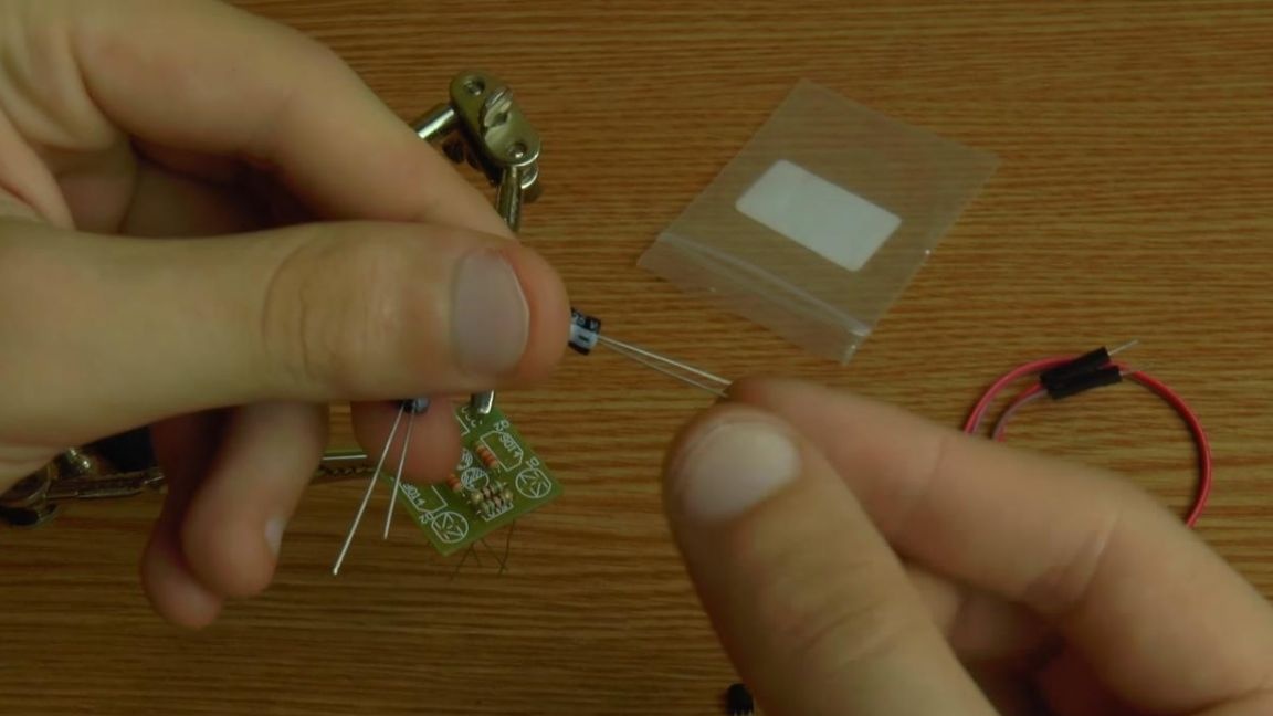
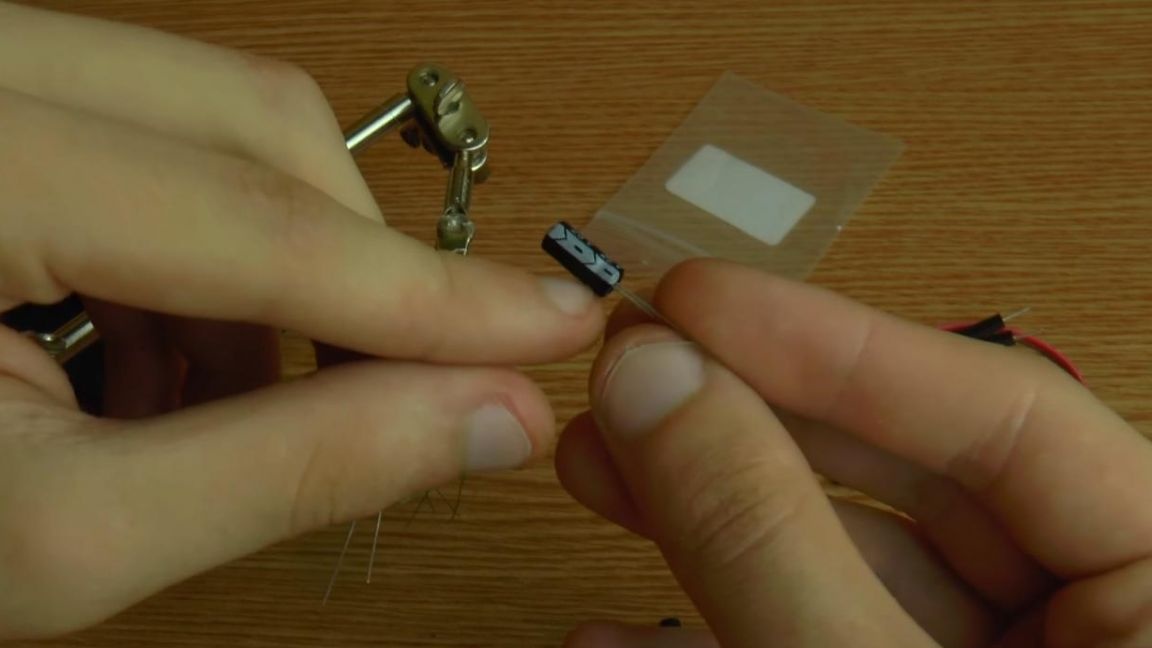
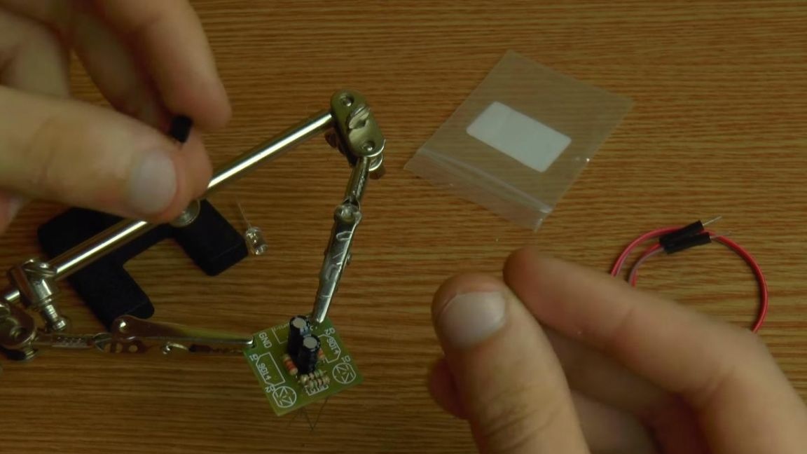
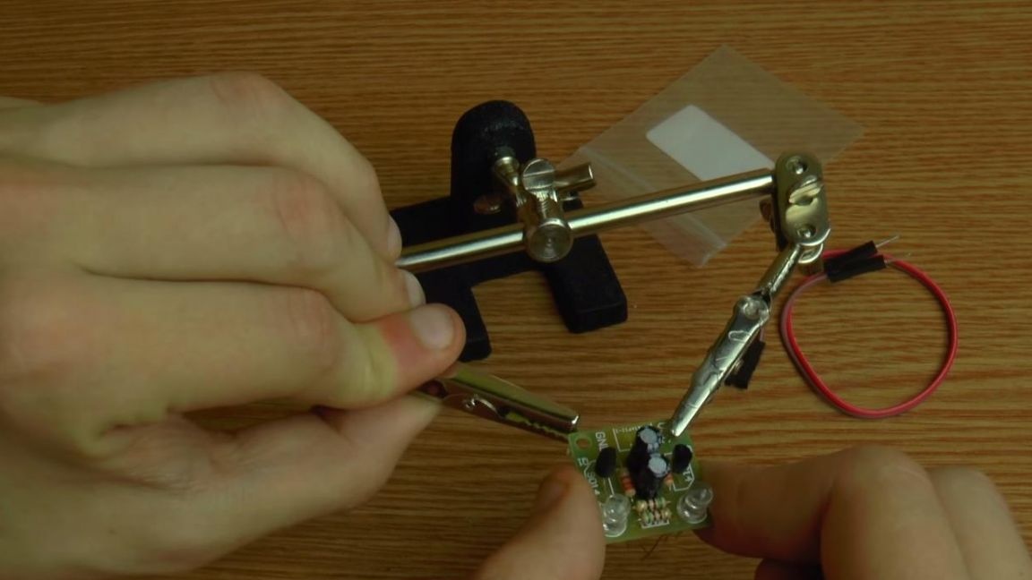
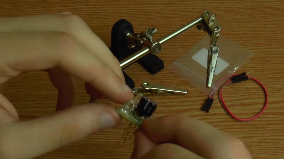
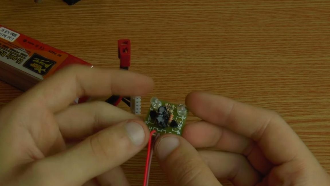
Now you need to install two transistors with the marking 9014, we arrange them according to the picture on the board, which repeats the contour of the semicircular body.
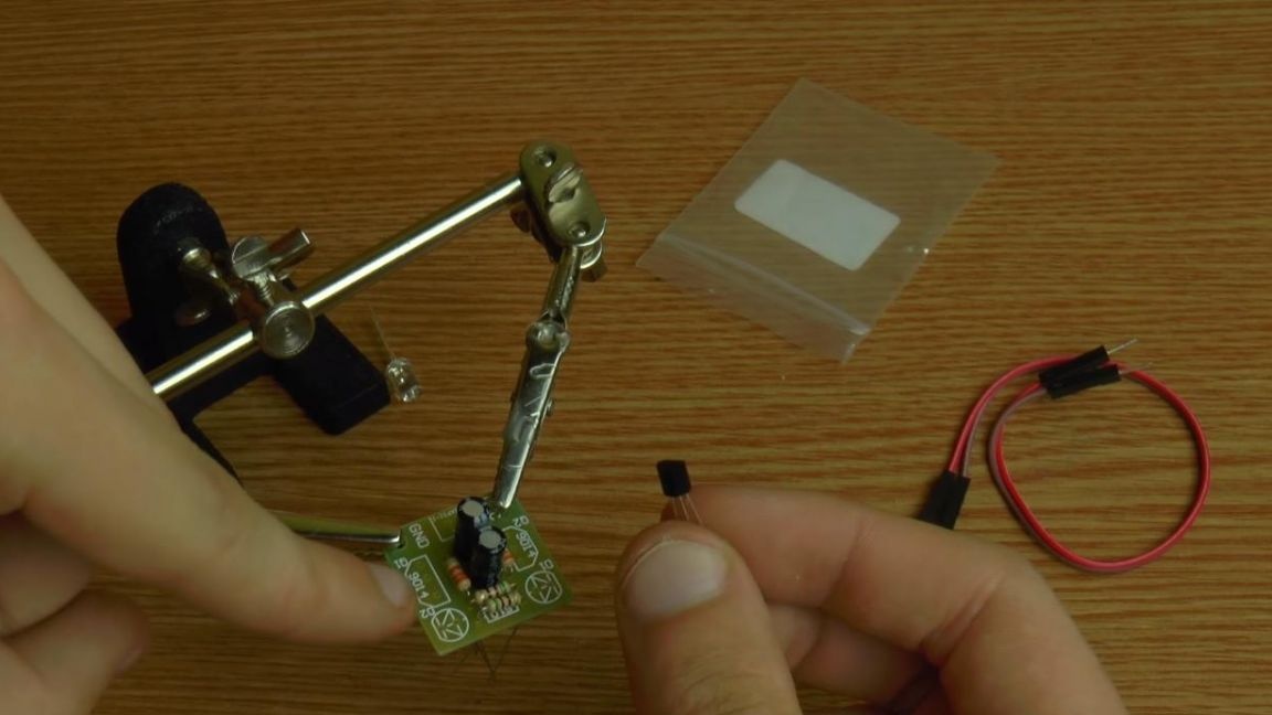
Next, put two LEDs. The long leg of the LED is a plus, a short minus. On the board itself, a triangle with a strip is depicted, a strip corresponds to a minus, a triangle to a plus terminal.
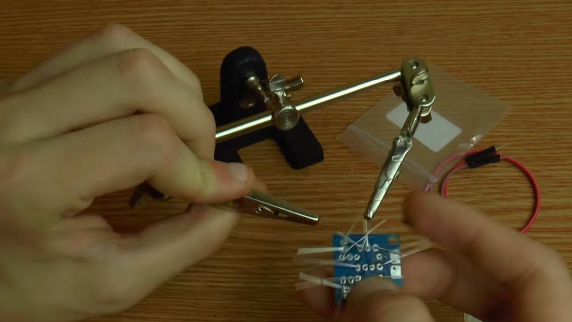
Step Four
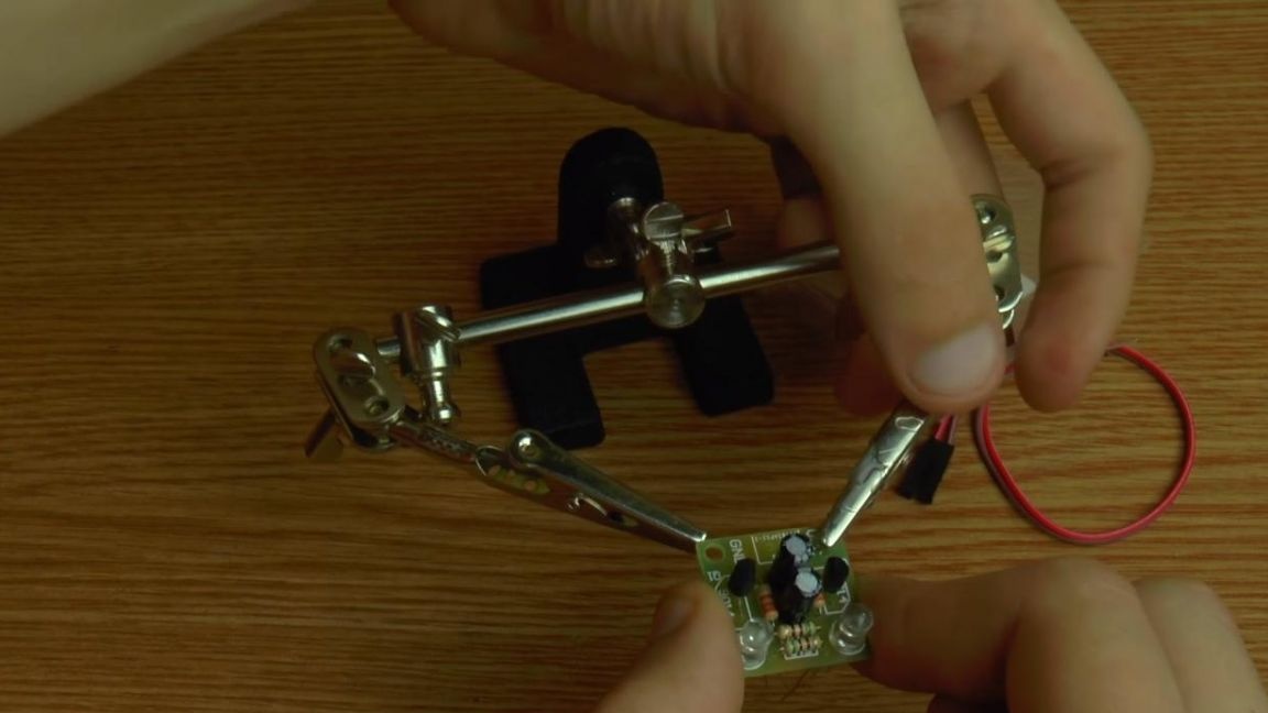
In order for all installed radio components not to fall out of the board openings, it is necessary to bend the terminals of the components.
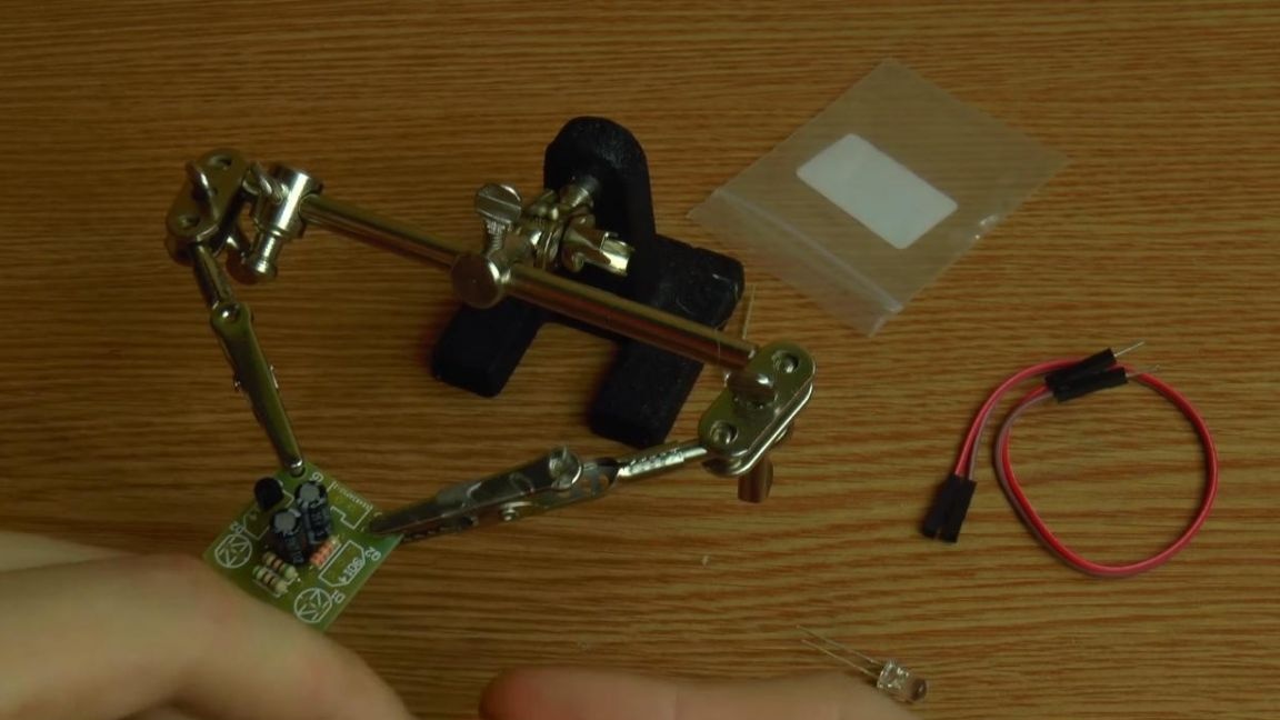
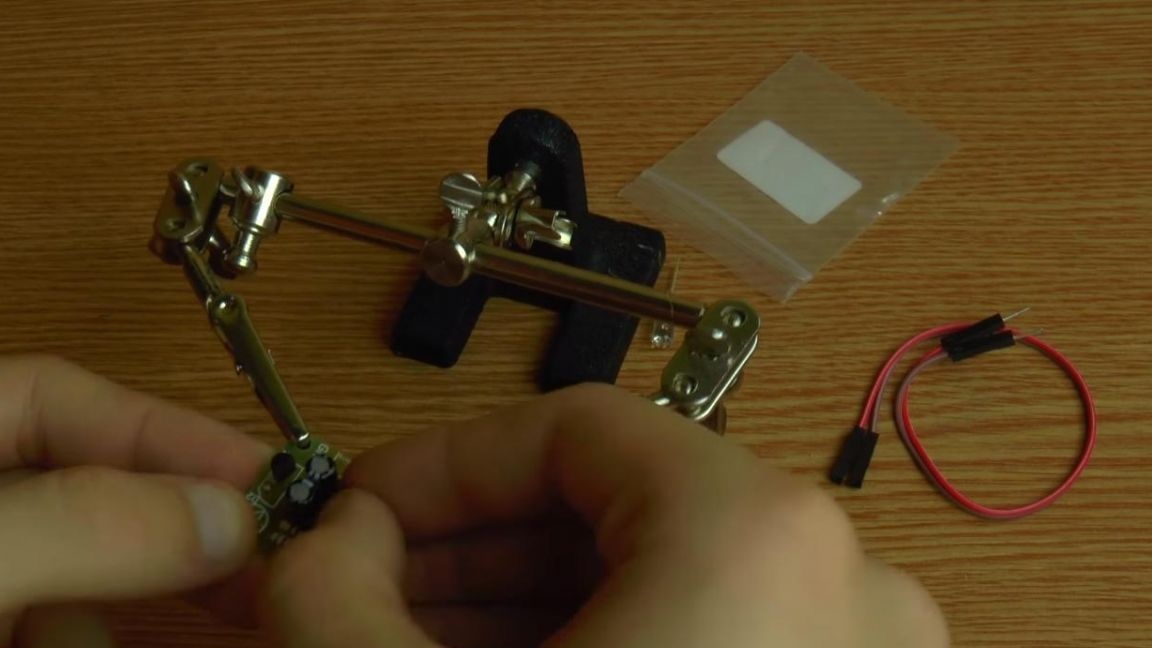
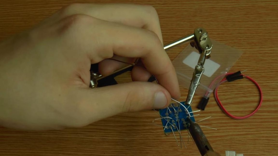
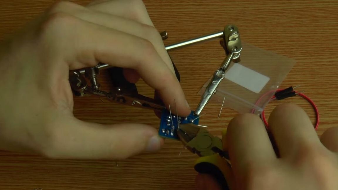
Next, we clamp the board in the soldering device "third hand" and apply the flux. After applying the flux to the contacts, solder the conclusions with a soldering iron.
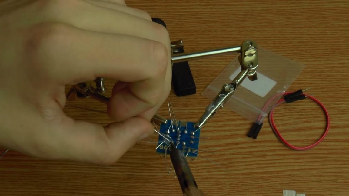
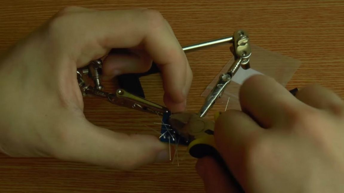
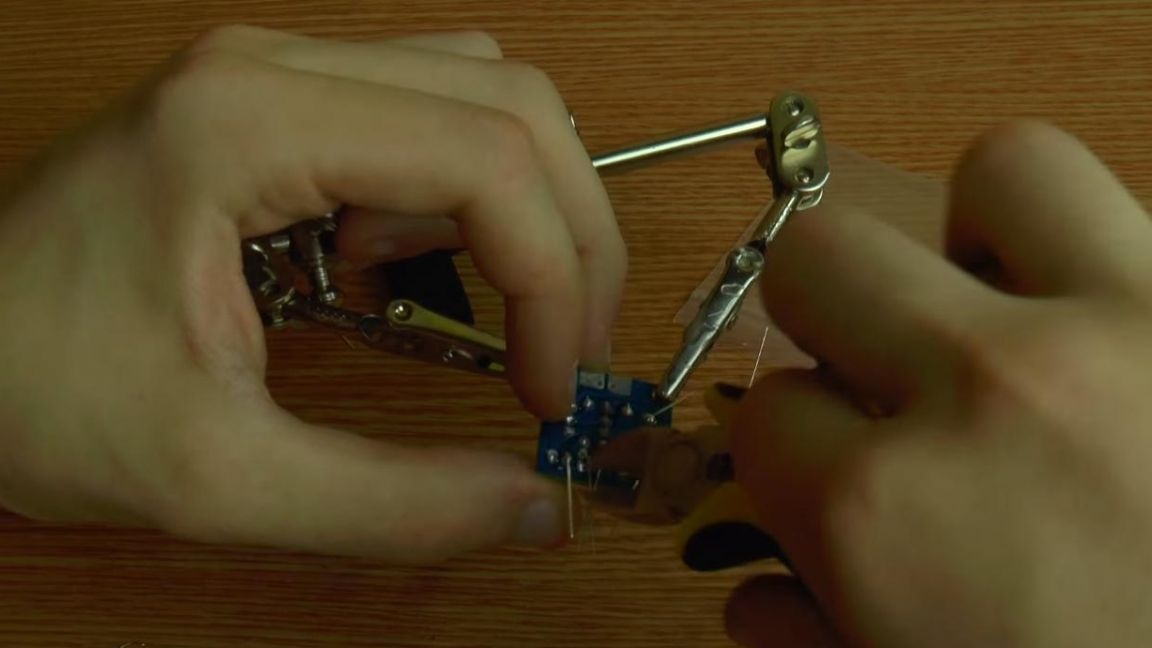
After soldering, we bite off the conclusions with the help of side cutters. When removing the excess part of the legs of the radio parts with side cutters, be careful, since the board tracks do not hold so tight and can be removed together in the output.
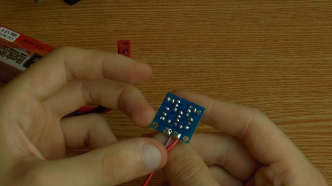
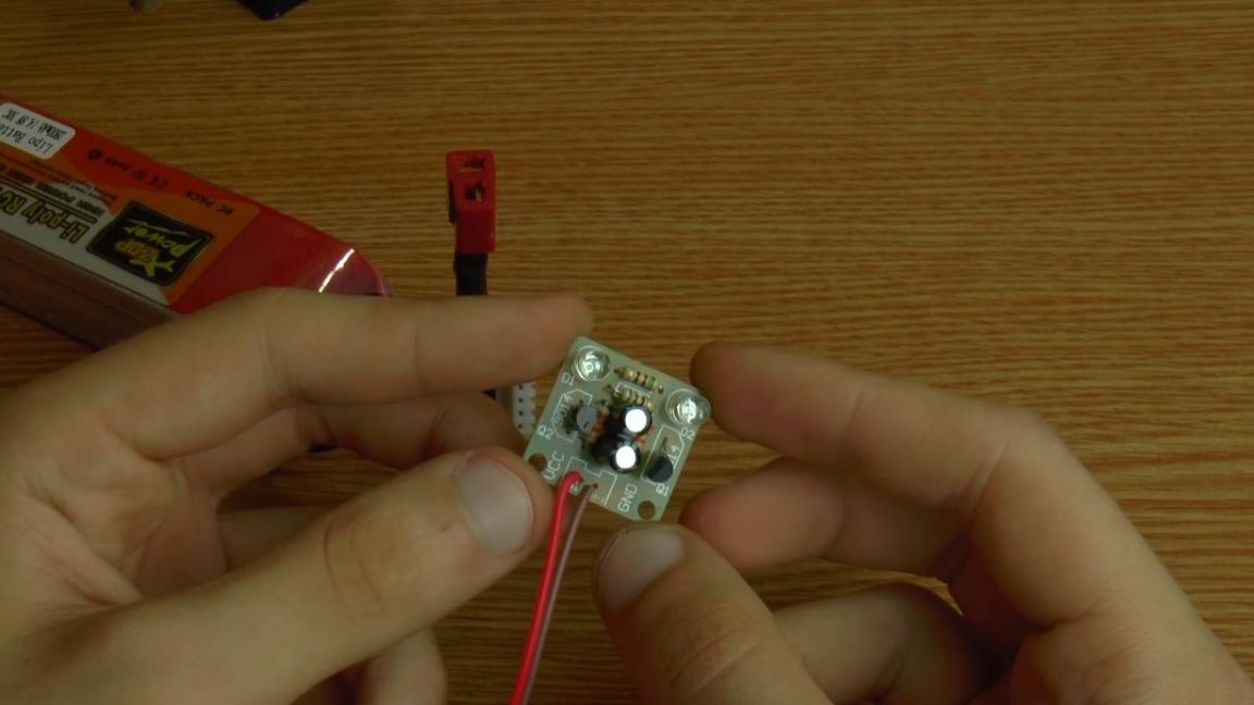
Then we solder the wires to connect the power and wash the board from the flux, for this acetone or galosh gasoline will work well.
Step Five
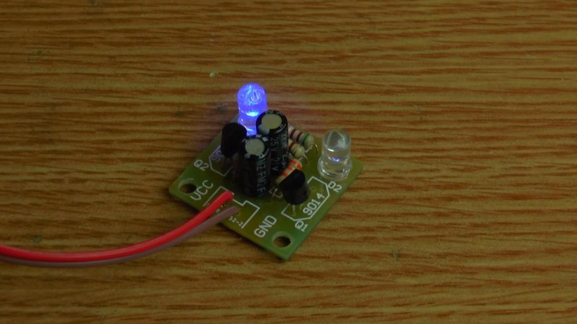
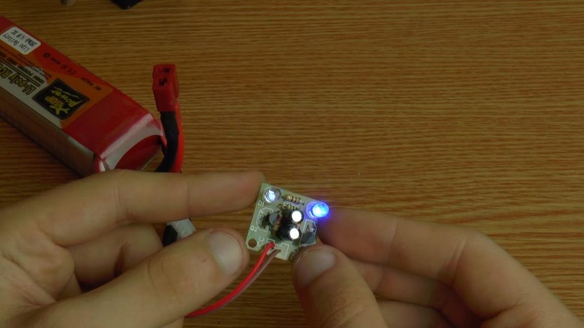
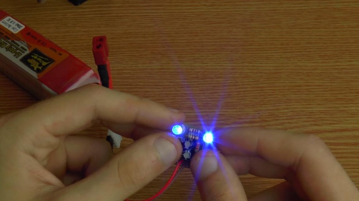
It's time to check the multivibrator, we connect the battery with a voltage of 3.7 volts. As you can see, the circuit has worked, the LEDs light up alternately.
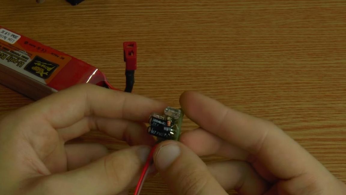
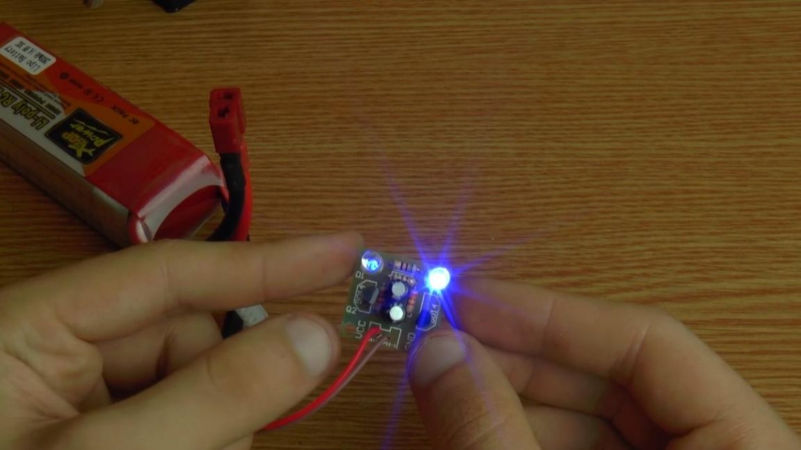
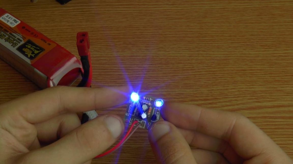
The blinking frequency can be changed by the capacity of two electrolytic capacitors, if it is reduced, the frequency will increase and, conversely, when the capacity is increased, the blinking frequency will decrease.
That's all for me, this homemade product is suitable for those who want to try themselves in the assembly of radio designers, as well as give an idea of the operation of the simplest radio components and help to master the basics of soldering.