

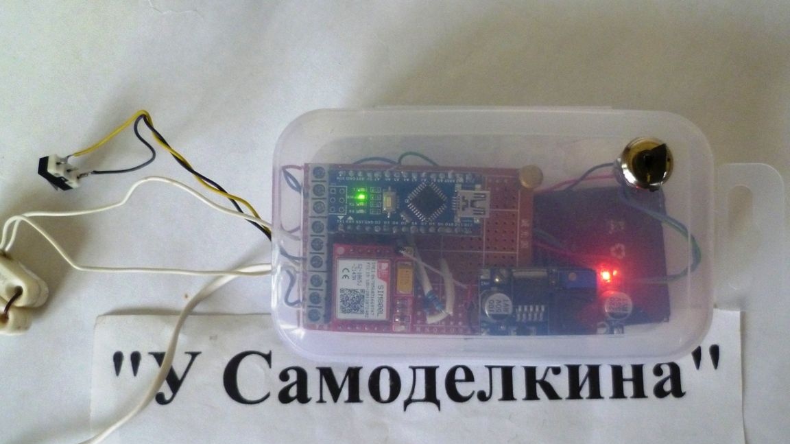
With the onset of the summer season, there was a need to protect the country house. I wanted to make a simple but reliable burglar alarm with a signal transmitted to a cell phone. It was decided to assemble a device with alarm transmission to a cell phone based on electronic circuit boards purchased on Aliexpress. As they say cheap but cheerful. The main elements of this design are the GSM SIM800L module and the Arduino board (you can use any Nano, Uno, Pro Mini and the like).
The device has five alarm inputs for contact sensors. One or several sensors connected in series can be connected to each input. In a sketch, assign a name to each security loop (for example, an entrance door, window 1, window 2, and so on). The security device works like this: when the electric circuit of the first loop is broken, the unit first makes a call to the first telephone of the subscriber, then stops the call and also to No. 2. No. 2 is necessary in view of the fact that if suddenly the first subscriber is offline or the battery and other troubles are hooked) If the loop following the first one is triggered, then an SMS message is sent with the name of the loop that worked, in the same case, to both subscriber numbers.
Enumeration of tools and materials.
lithium-ion battery from an old phone 3.7V \ 1600mA-1pc
-connecting wires;
soldering iron;
-tester;
-transparent plastic box -1pcs;
-pay Arduino Nano -1 pcs;
-resistors 10kOhm-7pcs;
- breadboard made of foil textolite;
- 1pcs power switch;
- SIM800L module -1pcs;
- lowering board 1-2A -1pcs;
- terminal connectors.
Step one. Assembling a circuit of a GSM security device.
Photo scheme.
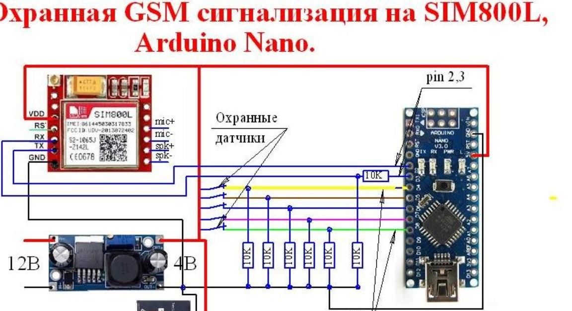
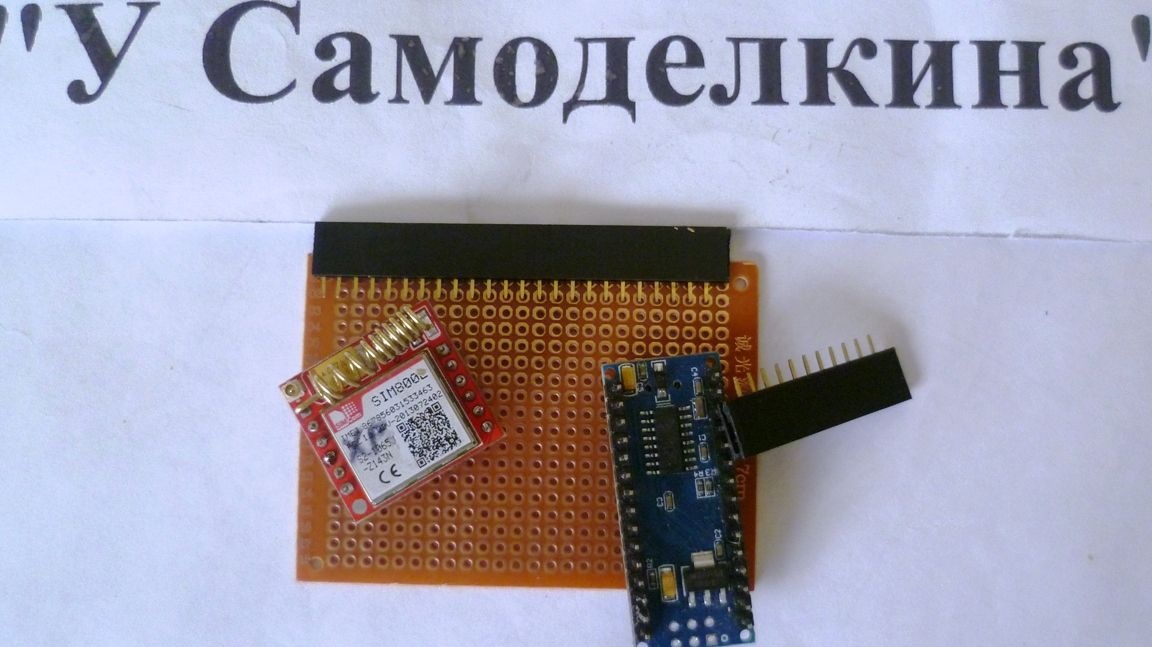
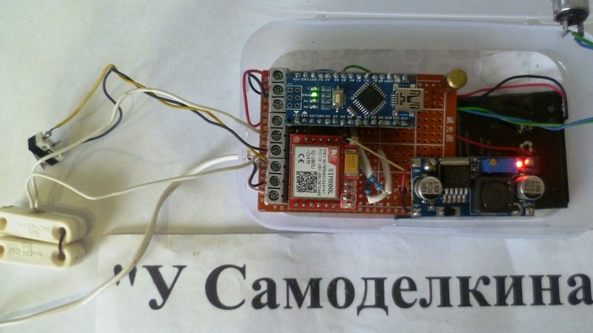
We solder plug-in pads for the GSM SIM800L module and the Arduino module onto the breadboard, this simplifies installation and makes it easy to replace modules if necessary. Solder resistors and other connections. The resistors from the RX pin of the SIM800L module are connected to the Arduino D3 digital input to match the voltage of the inputs of both modules. Arduino D4-D8 inputs are pulled through resistors. The switch is mounted in the power supply gap of the SIM800 GSM module and the Arduino board for arming the entire system. The use of a battery, which will allow the device to function for two three days in the absence of a 220 V network. In my case, the voltage converter from the voltage of 12 V produces a voltage of 4.2 V and at the same time charges the battery (you can use another board, for example TP4056 with protection).
Second step. Device programming.
In the SIM card, PIN codes and all unnecessary functions should be deleted.Still, you first need to configure the SIM800L module itself. There are a lot of videos on this topic on the network, there is nothing complicated about it. In the sketch we indicate your phone numbers, adjust the names of the security zones, you can set the time for monitoring the system (if the device is working properly after a specified time, a control SMS will come). Fill the sketch in Arduino and check the operation of the device.
Sketch:
String numberCall_1 = "79123456789"; // Subscriber number №1 for a call
String numberSMS_1 = "+79123456789"; // Subscriber number No. 1 for SMS (differs only in the + sign)

String numberCall_2 = "79123456782"; // Subscriber number 2 for a call
String numberSMS_2 = "+79123456782"; // Subscriber number No. 2 for SMS (differs only in the + sign)

String textZone_1 = "Alarm! Zone1"; // Its name is in Latin.
String textZone_2 = "Alarm! Zone2"; // Its name is in Latin.
String textZone_3 = "Alarm! Zone3"; // Its name is in Latin.
String textZone_4 = "Alarm! Zone4"; // Its name is in Latin.

#include
SoftwareSerial mySerial (2, 3);

#define pinSensor_0 4
#define pinSensor_1 5
#define pinSensor_2 6
#define pinSensor_3 7
#define pinSensor_4 8

void initGSM (void) {
  delay (2000);
  mySerial.begin (9600); // Set the communication speed with the GSM module 9600 Baud / sec.
  mySerial.println ("AT + CLIP = 1");
  delay (300);
  mySerial.println ("AT + CMGF = 1");
  delay (300);
  mySerial.println ("AT + CSCS = \" GSM \ "");
  delay (300);
  mySerial.println ("AT + CNMI = 2,2,0,0,0");
  delay (300);
}

/ * SMS sending * /
void sendSMS (String text, String phone) {
  mySerial.println ("AT + CMGS = \" "+ phone +" \ "");
  delay (500);
  mySerial.print (text);
  delay (500);
  mySerial.print ((char) 26);
  delay (2500);
}


unsigned long timerTemp = 0;
uint8_t hours = 0;

uint8_t flagSensor_0 = 0;
uint8_t flagSensor_1 = 0;
uint8_t flagSensor_2 = 0;
uint8_t flagSensor_3 = 0;
uint8_t flagSensor_4 = 0;

void setup () {
  mySerial.begin (9600);
  initGSM ();

  pinMode (pinSensor_0, INPUT);
  pinMode (pinSensor_1, INPUT);
  pinMode (pinSensor_2, INPUT);
  pinMode (pinSensor_3, INPUT);
  pinMode (pinSensor_4, INPUT);

  timerTemp = millis ();
}

void loop () {
    if (millis () - timerTemp> = 3600000) {timerTemp = millis (); hours ++;}

  if (hours> = 144) {// Change the system control time to our own, 144 hours. number of hours.
    sendSMS (String ("The system works normally.OK"), numberSMS_1);
    delay (10000);
    sendSMS (String ("The system works normally.OK"), numberSMS_2);
    delay (10000);
    hours = 0;
    timerTemp = millis ();
  }

  if (flagSensor_0 == 0 && digitalRead (pinSensor_0) == 0) flagSensor_0 = 1;
  if (flagSensor_1 == 0 && digitalRead (pinSensor_1) == 0) flagSensor_1 = 1;
  if (flagSensor_2 == 0 && digitalRead (pinSensor_2) == 0) flagSensor_2 = 1;
  if (flagSensor_3 == 0 && digitalRead (pinSensor_3) == 0) flagSensor_3 = 1;
  if (flagSensor_4 == 0 && digitalRead (pinSensor_4) == 0) flagSensor_4 = 1;

  if (flagSensor_0 == 1) {
    String command;

    command = "ATD +" + numberCall_1 + ";"
    mySerial.println (command);
    delay (20000);
    mySerial.println ("ATH");
    delay (1000);


    command = "ATD +" + numberCall_2 + ";";
    mySerial.println (command);
    delay (20000);
    mySerial.println ("ATH");
    delay (1000);

    flagSensor_0 = 2;
  }


  if (flagSensor_1 == 1) {
    sendSMS (textZone_1, numberSMS_1);
    delay (10000);
    sendSMS (textZone_1, numberSMS_2);
    delay (10000);
    flagSensor_1 = 2;
  }


  if (flagSensor_2 == 1) {
    sendSMS (textZone_2, numberSMS_1);
    delay (10000);
    sendSMS (textZone_2, numberSMS_2);
    delay (10000);
    flagSensor_2 = 2;
  }


  if (flagSensor_3 == 1) {
    sendSMS (textZone_3, numberSMS_1);
    delay (10000);
    sendSMS (textZone_3, numberSMS_2);
    delay (10000);
    flagSensor_3 = 2;
  }


  if (flagSensor_4 == 1) {
    sendSMS (textZone_4, numberSMS_1);
    delay (10000);
    sendSMS (textZone_4, numberSMS_2);
    delay (10000);
    flagSensor_4 = 2;
  }

  if (flagSensor_0 == 2 && digitalRead (pinSensor_0)! = 0) flagSensor_0 = 0;
  if (flagSensor_1 == 2 && digitalRead (pinSensor_1)! = 0) flagSensor_1 = 0;
  if (flagSensor_2 == 2 && digitalRead (pinSensor_2)! = 0) flagSensor_2 = 0;
  if (flagSensor_3 == 2 && digitalRead (pinSensor_3)! = 0) flagSensor_3 = 0;
  if (flagSensor_4 == 2 && digitalRead (pinSensor_4)! = 0) flagSensor_4 = 0;
}
Step three. Checking the health of the device.
When power is applied, while the SIM800L module and Arduino board are loading, you have about 20 seconds to leave the guarded room. On the SIM800L module, the LED indicates network operation - this network search often blinks, once every five seconds - network operation. When the device finds a network, disconnect the corresponding security inputs, after this there will be dialing or sending SMS. So the device is working fine.
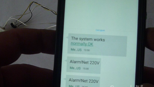
Photo SMS. It will be possible to include any security detectors with outputs in the form of contacts, relays from actuators, only in accordance with your needs and imagination. In general, we manufactured a simple, security device. Such a homemade watchman can be made to organize the protection of any objects. To turn on the alarm device, you need to supply 4.2 Volts through the switch on the SIM800 and Arduino. At the first entrance, a call will pass to subscriber No. 1, after which it will switch to No. 2. Additional No. 2 is provided for duplication. The open loop number 2,3,4,5 makes the issuance of SMS with the specific name of the broken loop, respectively, on both phones. We will place all boards in any in a suitable case. In general, I think this is a good interesting device that can be further developed further - add the functions of a GSM socket, DMTF control and much more.
More details can be seen in the video
I wish you all health and success in life and work!