
Hello to all lovers homemade. Many beginner radio amateurs are wondering how to make a laboratory power supply with the ability to adjust the current and voltage, ready-made solutions are quite expensive, so you have to turn your mind to it. In this article I will tell you how to make a laboratory power supply do it yourself, in the assembly of which the kit kit will help, it can be ordered by the link at the end of the article.
Before you read the article, I suggest watching a video with the complete process of assembling this kit kit and checking for its performance.
In order to make a laboratory power supply yourself, you will need:
* Kit
* Soldering iron, solder, flux
* Side cutters
* Device for soldering "third hand"
* Phillips screwdriver
* Transformer
Step one.
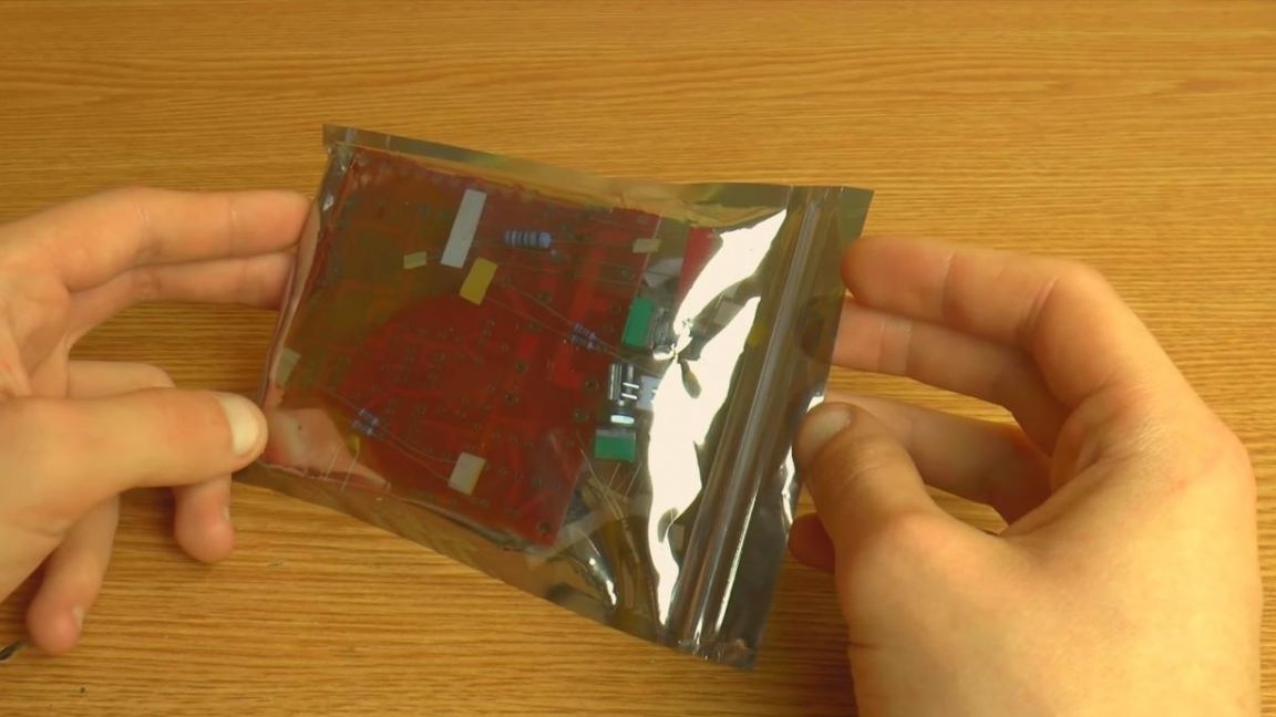
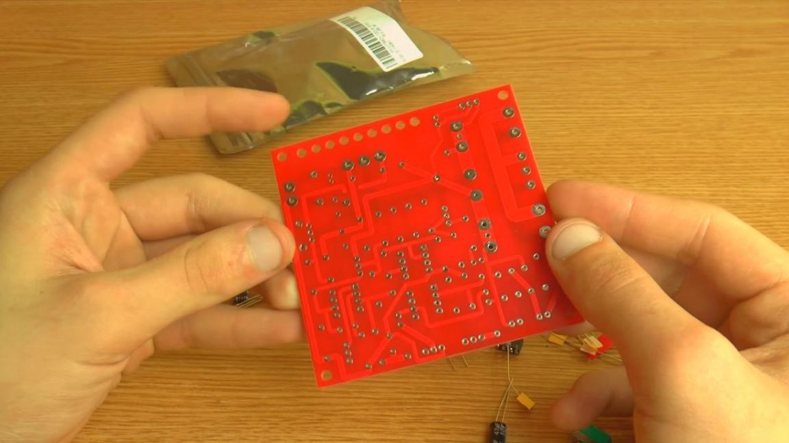
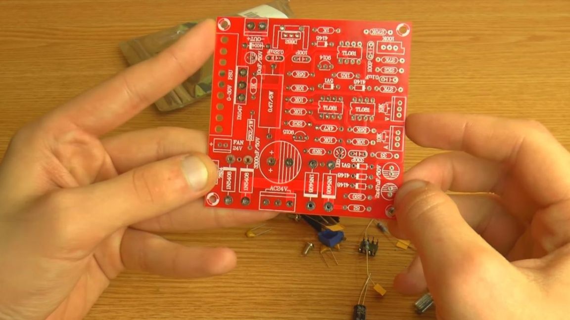
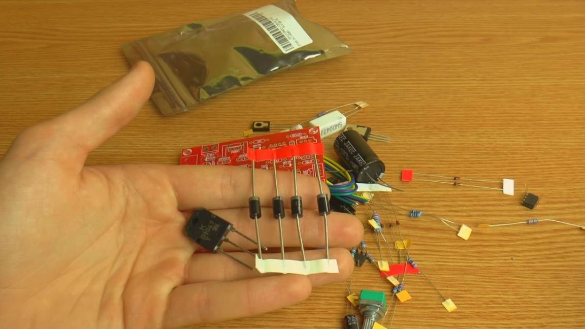
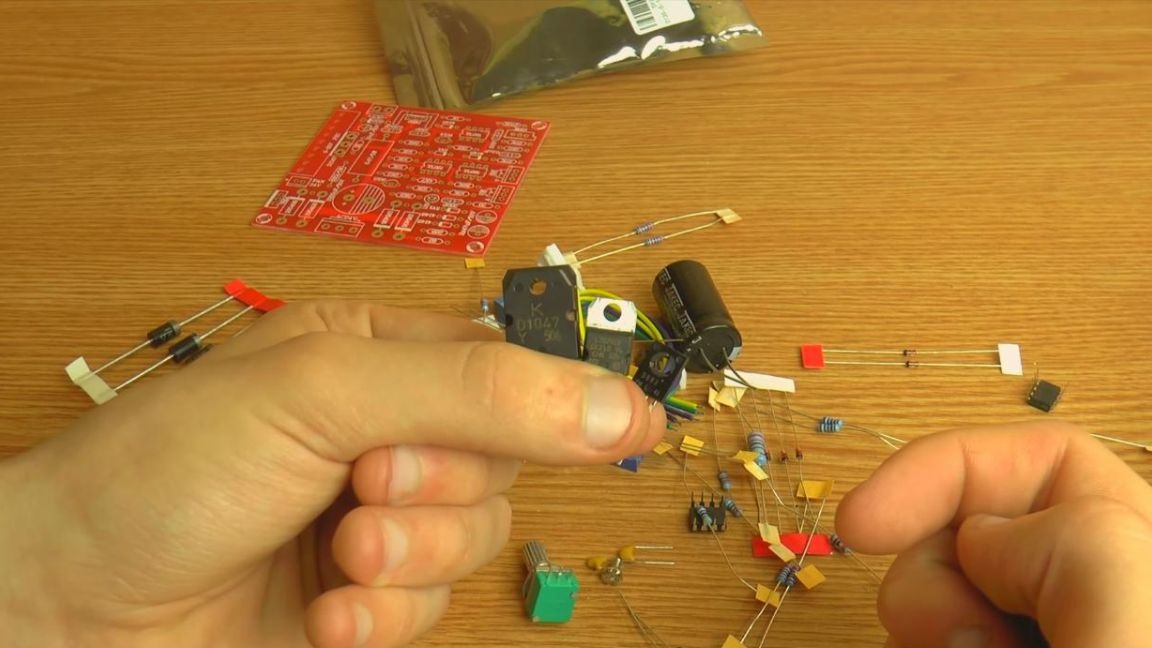
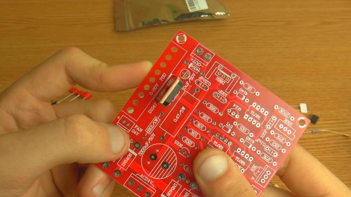
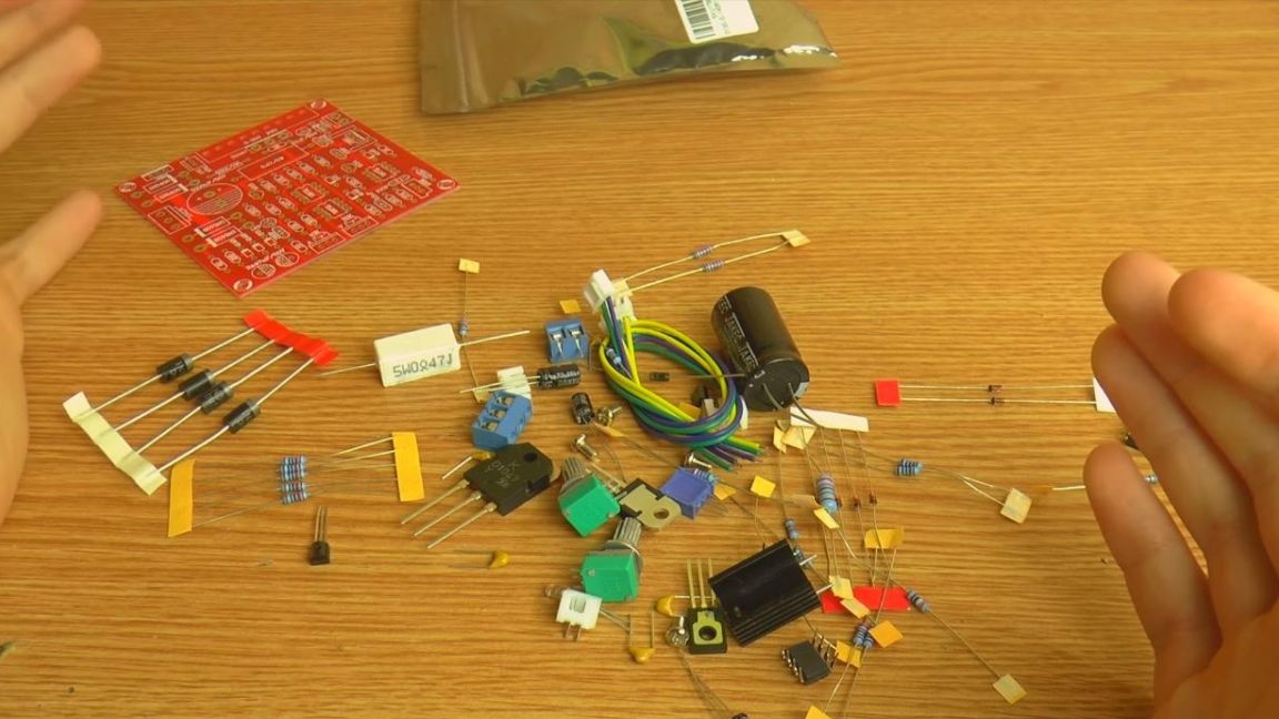
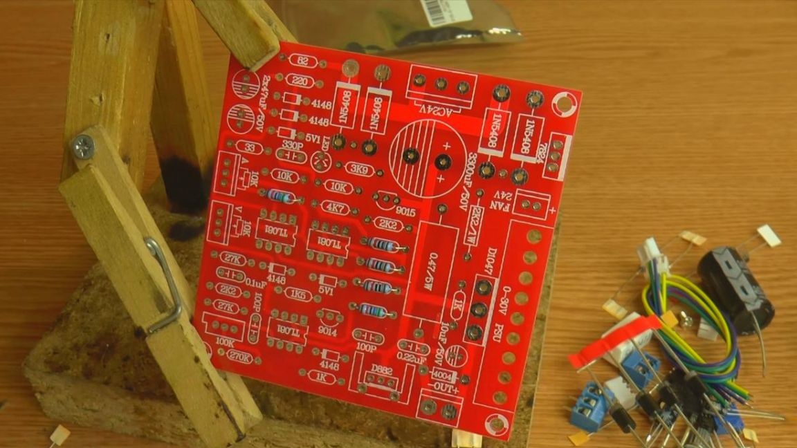
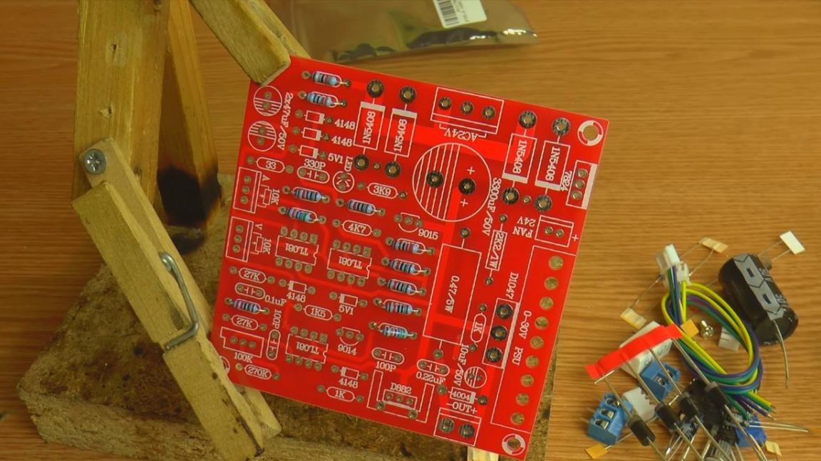
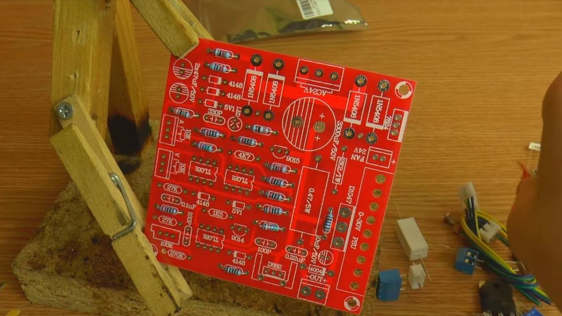
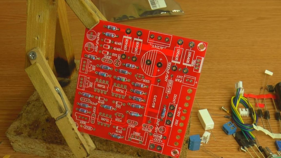
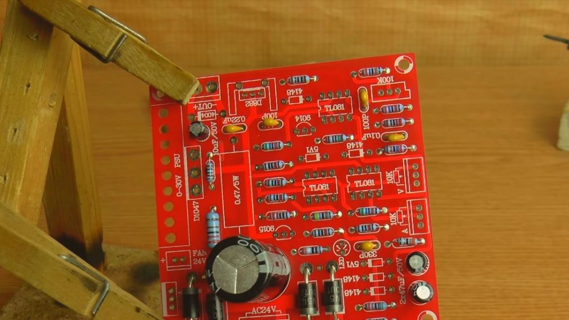
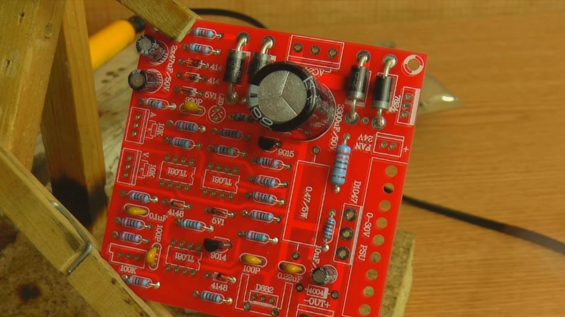
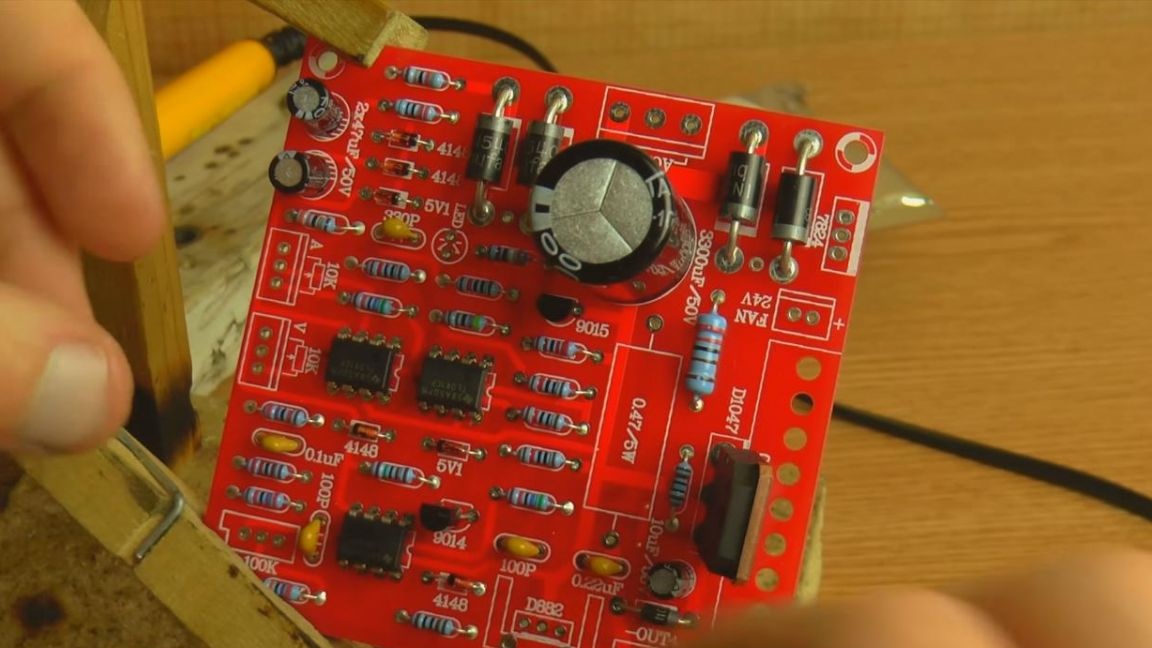
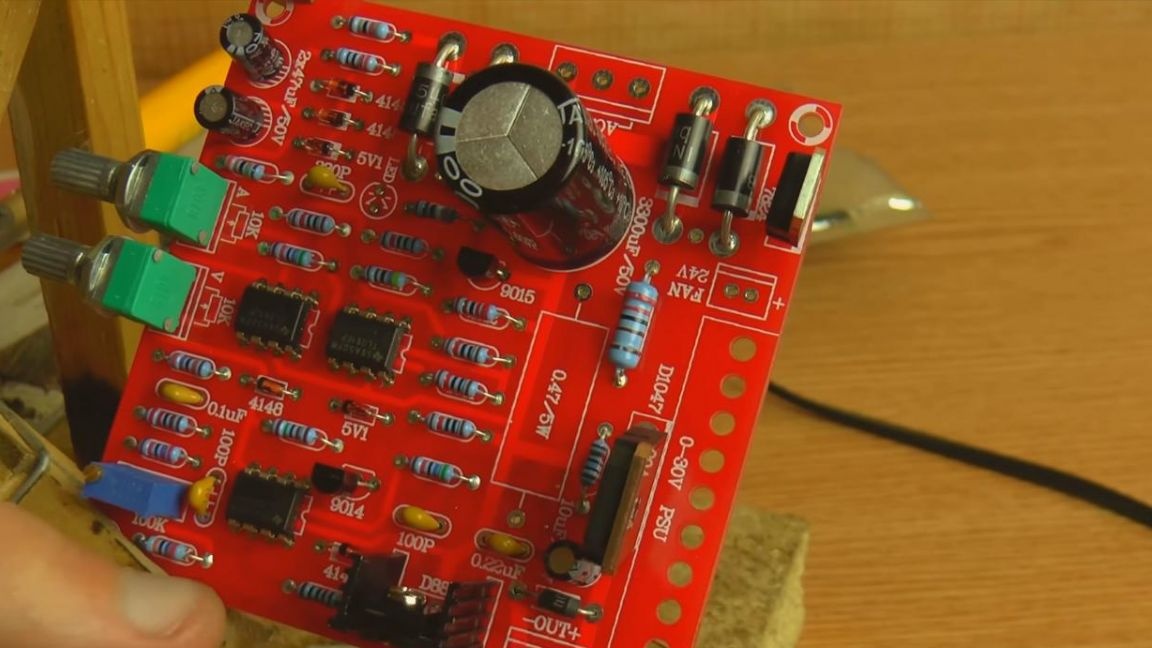
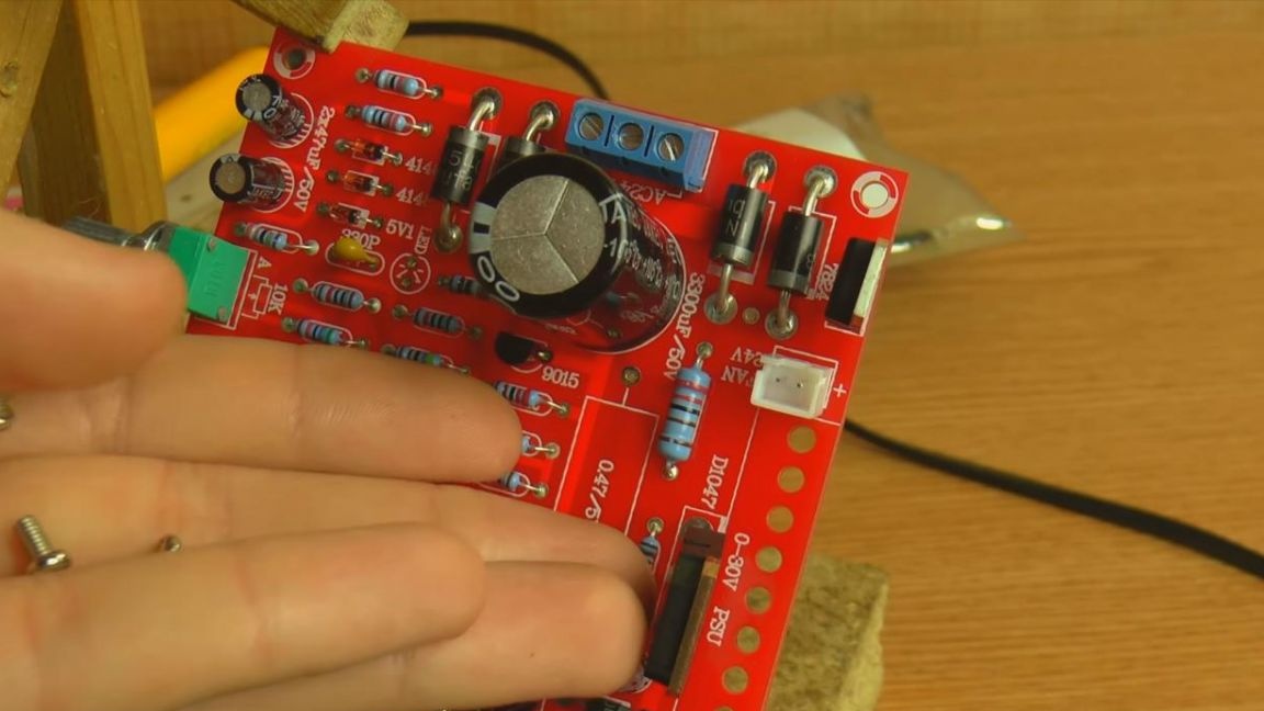
First, we will deal with the presence of parts that come with a kit. In this kit, there are a lot of components, the circuit board is made with high quality and indicating almost all the ratings of the radio components, which is very convenient, because the instructions are not included in the kit.
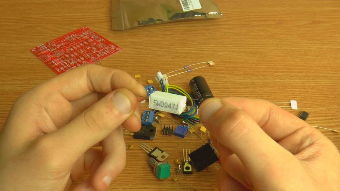
Since the power supply itself is designed for a sufficiently large power, some of its components look more serious compared to a simple low-power power supply, for example, a 5-watt resistor or diodes.
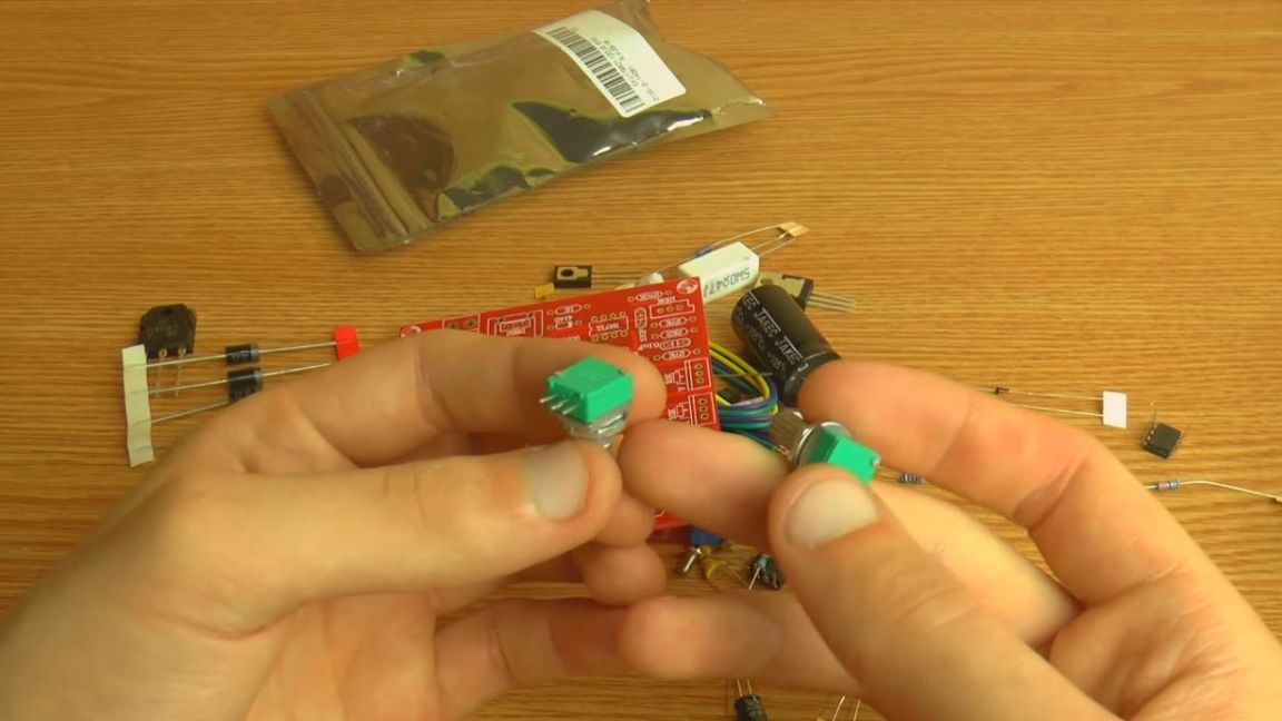
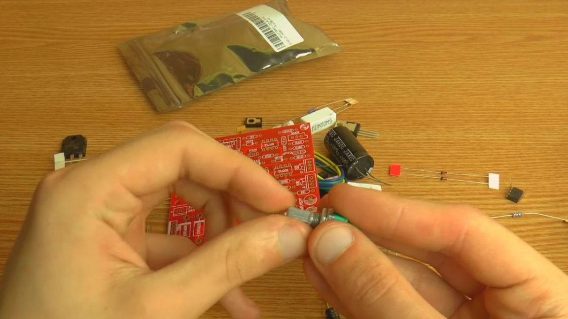
Also put variable resistors that will allow you to adjust the current strength and voltage.
The only thing that is not clear is that there is only one radiator per small transistor in the kit, although in the circuit itself there are two of them and obviously requires cooling, since the board has the ability to connect a fan.
Step Two
Now we pass directly to the assembly.
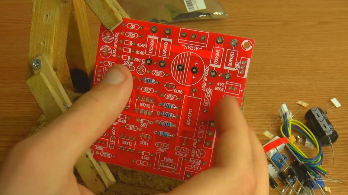
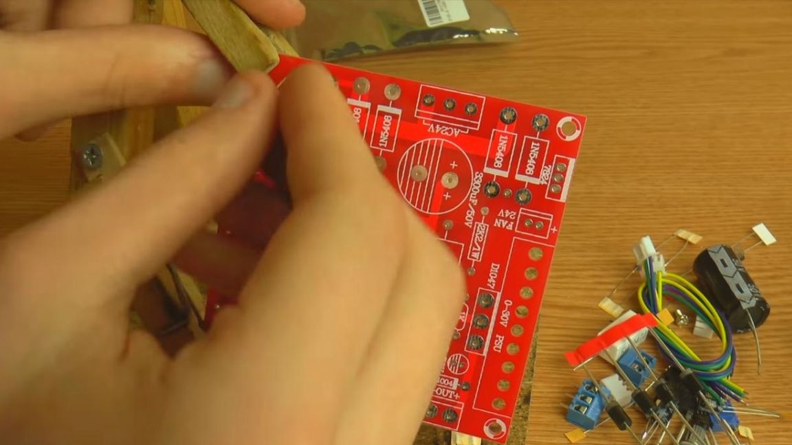
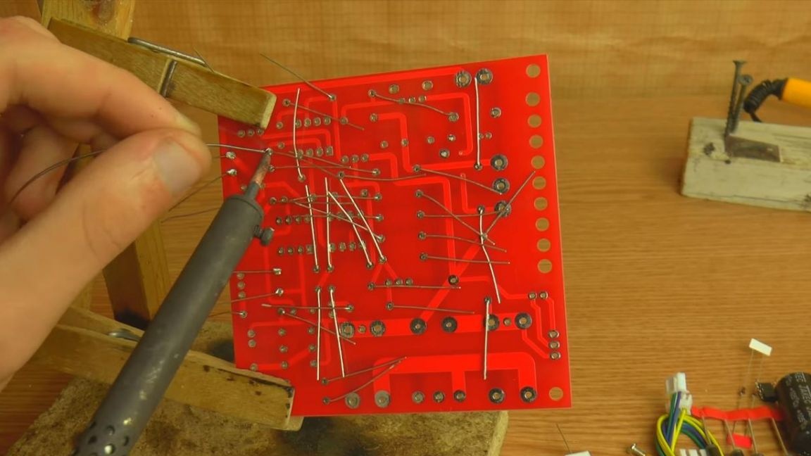
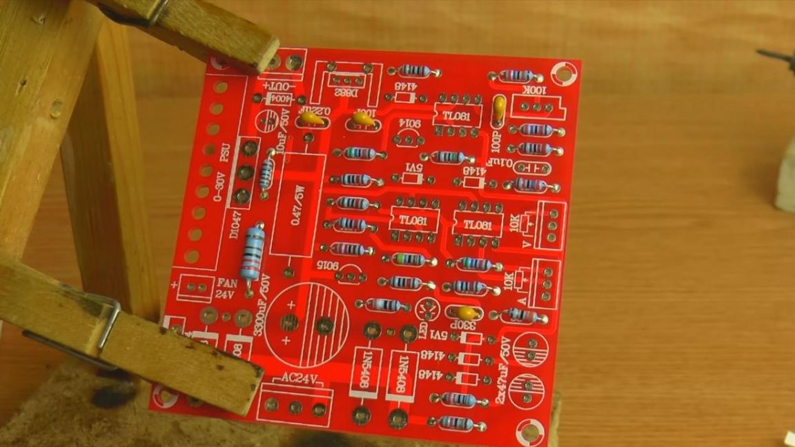
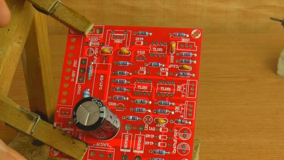
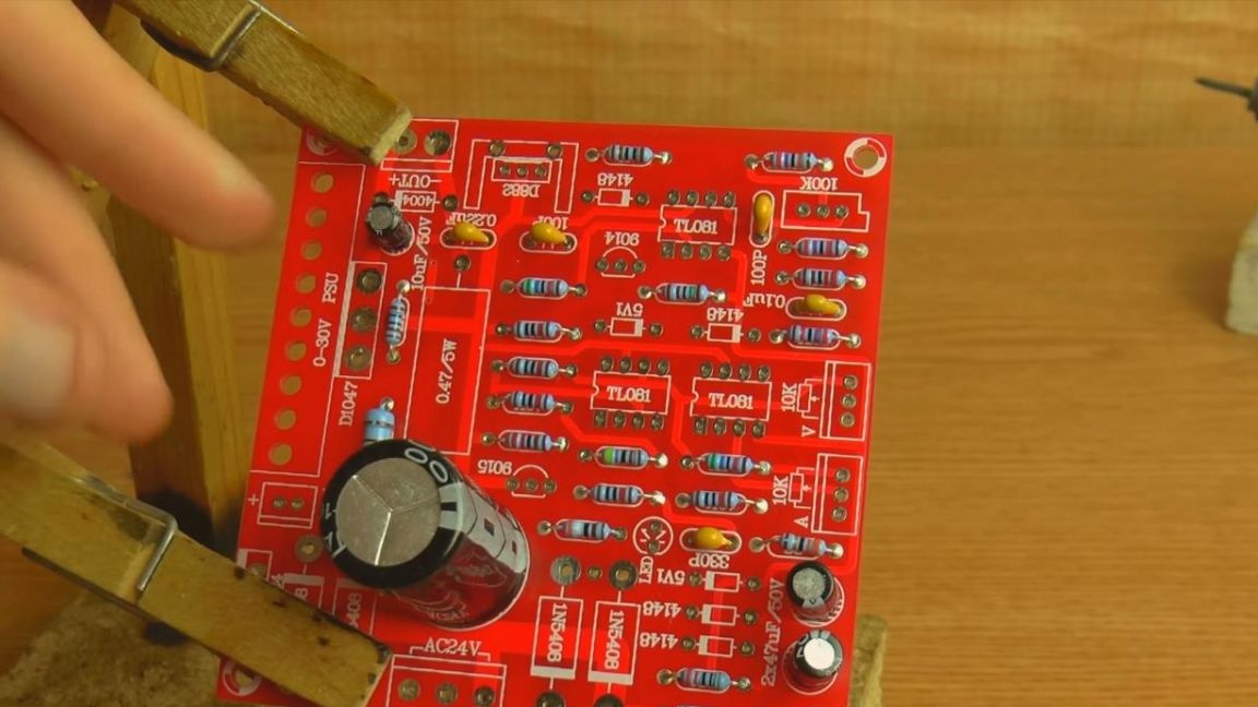
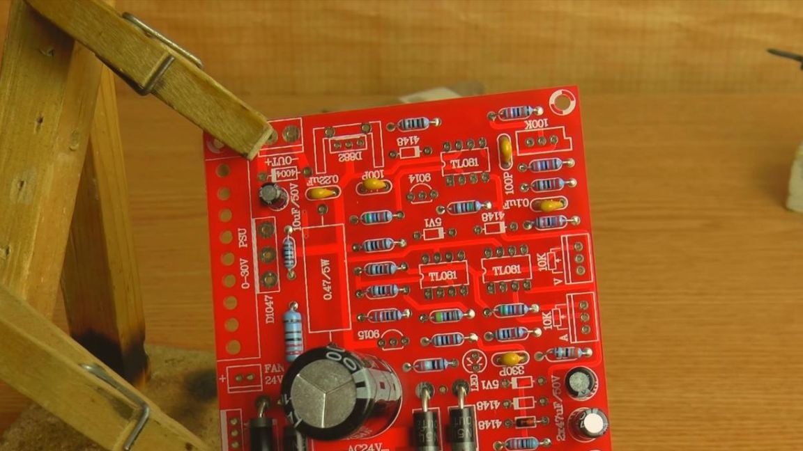
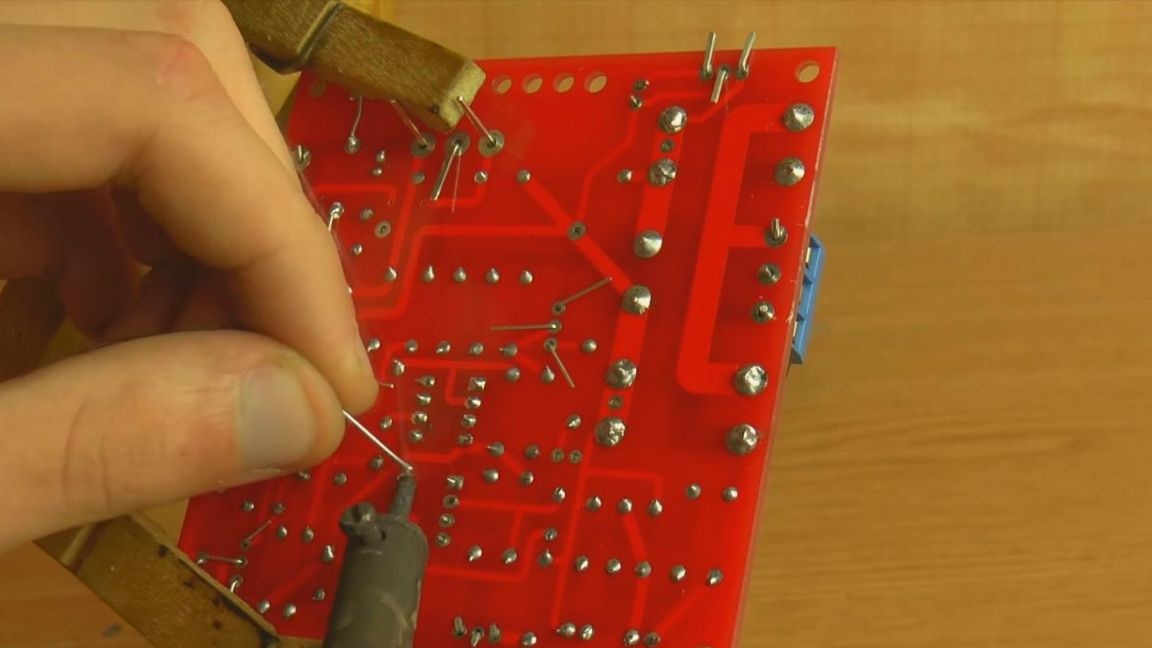
According to the classics of the genre, first of all, we install the board on a special device for soldering "third hand" and we put resistors in the fixed board.
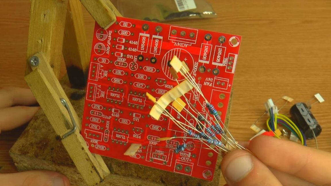
In this case, the resistor values are not indicated on the leaflet, as is the case in other sets, so you will have to determine the resistance of each resistor separately.
You can determine the resistance in several ways, using a multimeter, color coding and an online calculator. The first method is the simplest and fastest, but if you do not have this device, then the other two options are also working, they only require a little more time to determine.
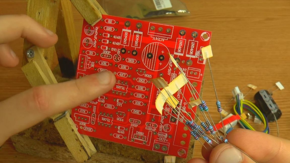
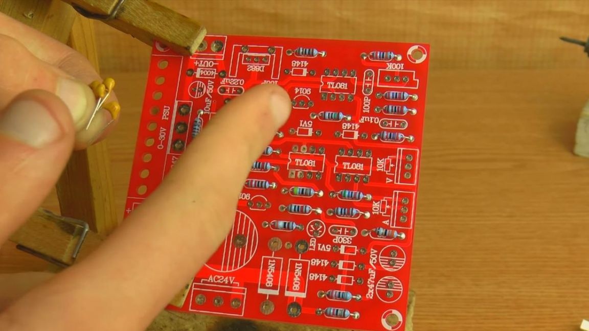
The good thing is that the values of the resistors are indicated on the board itself, therefore, having determined their resistance in a convenient way for you, we install them in their places. Next, we pry up the terminals of the radio components from the reverse side and solder to the board contacts with a soldering iron.
Step Three
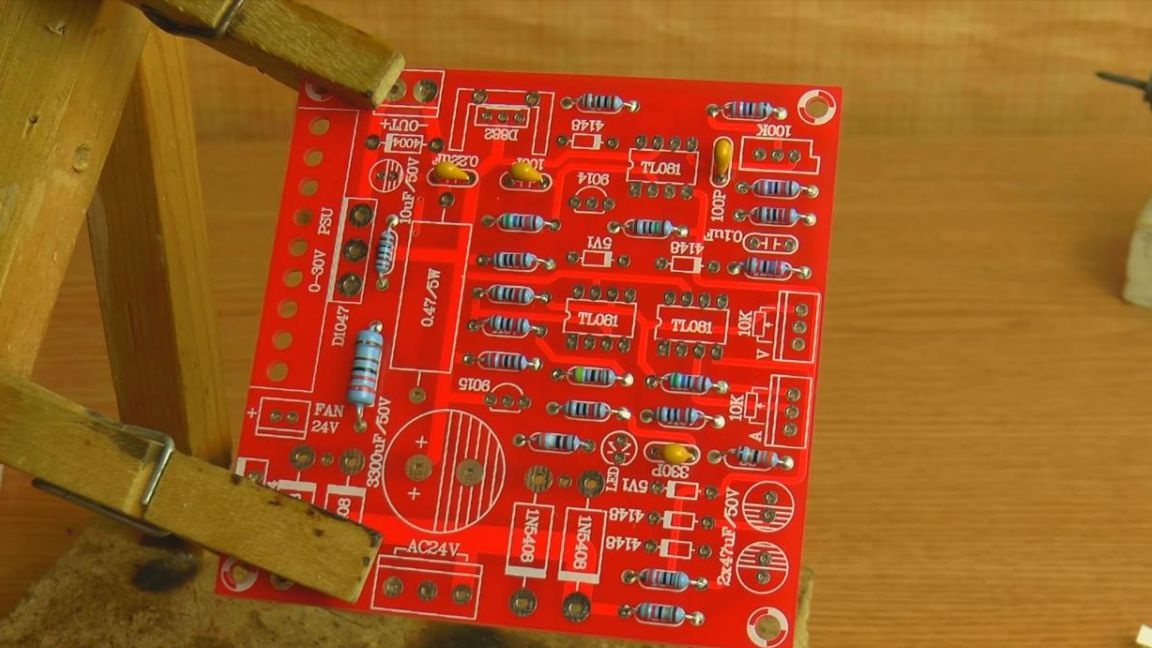
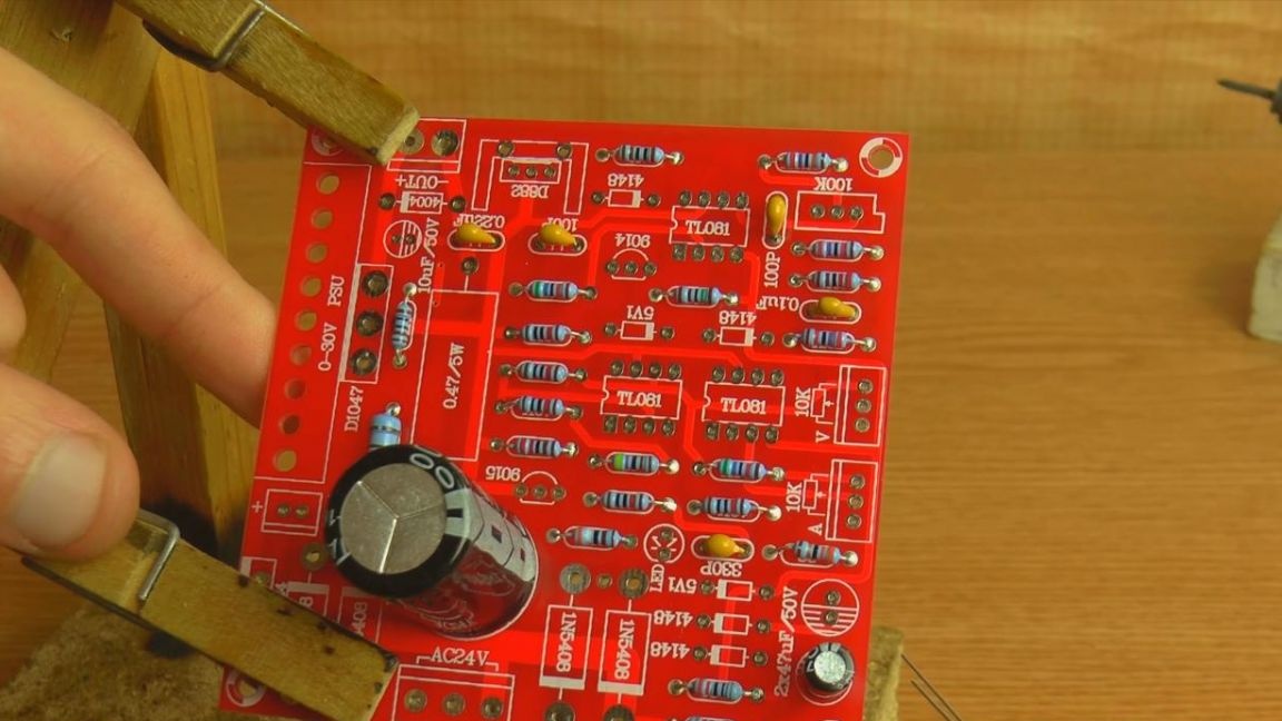
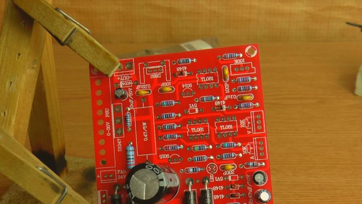
After the resistors, we place on the board non-polar ceramic capacitors.
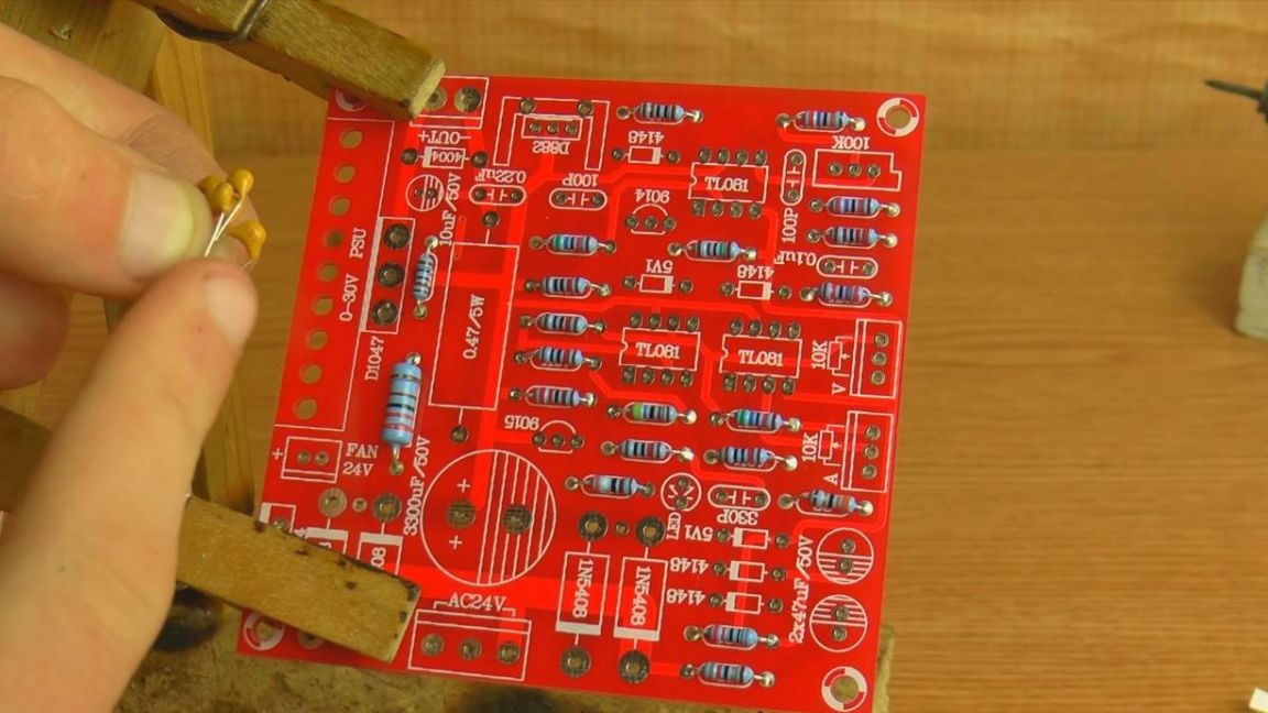
Their values can be determined using numbers, or the so-called code marking indicated on the case, for example, the number 101 means that the capacitance of this capacitor is 100 pF, but if the number is 104 on the case, then we get a capacity of 100 000 pF, which is 0, 1 uF, the third digit, in this case 4 it is a factor, and the first two are a numerical value. Having determined the capacitance, we install the capacitors in their places on the board.


Step Four
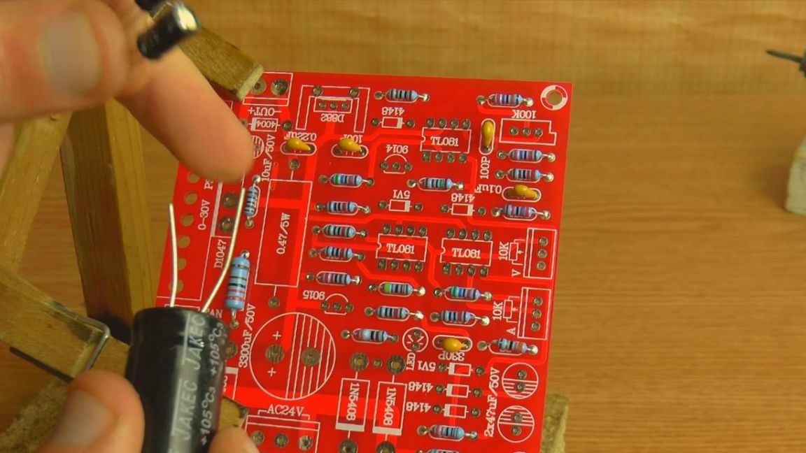
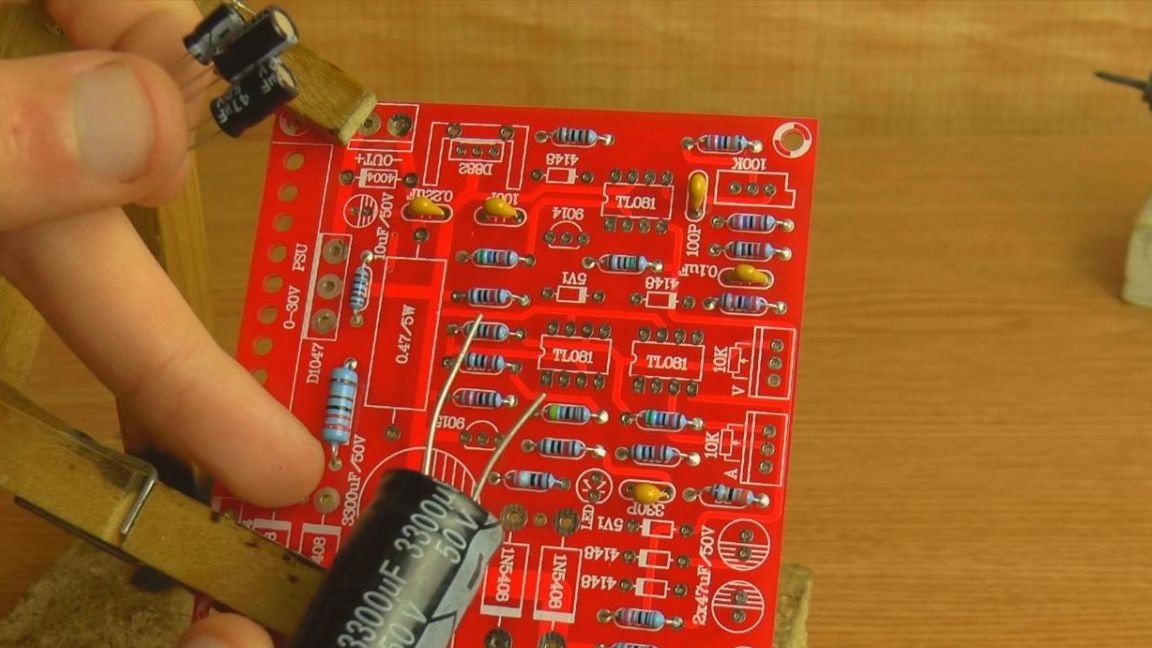
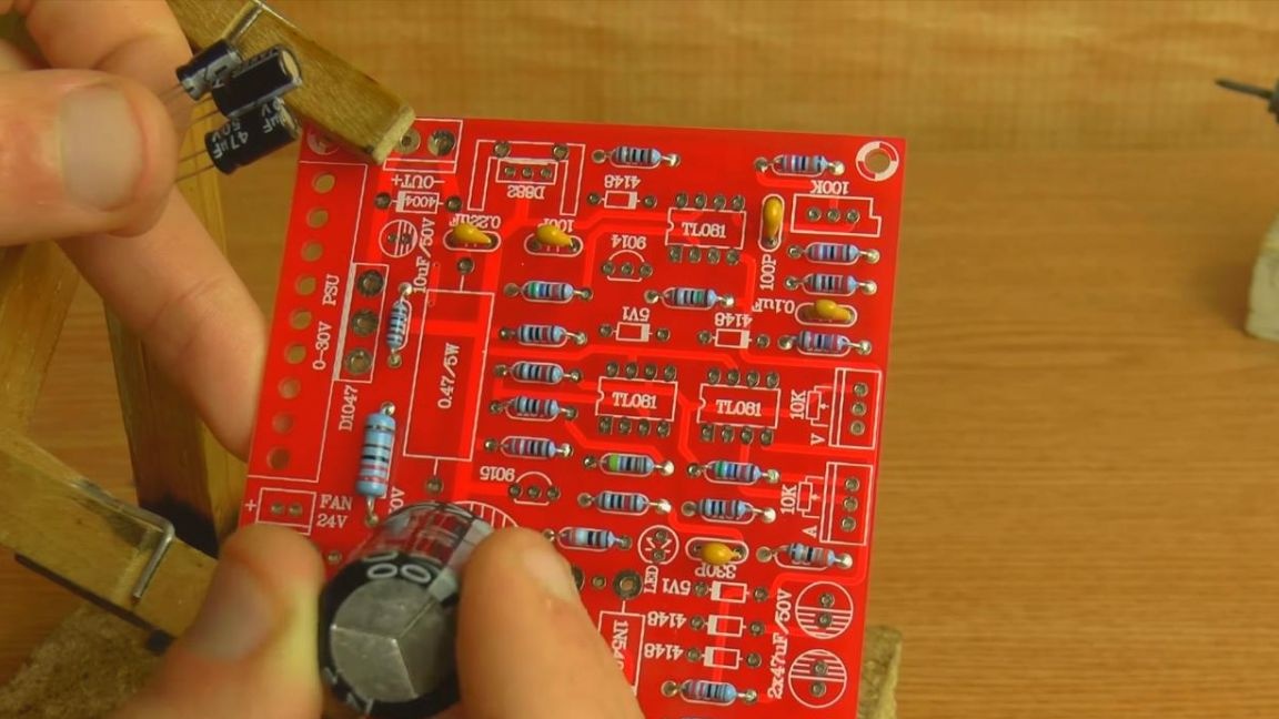
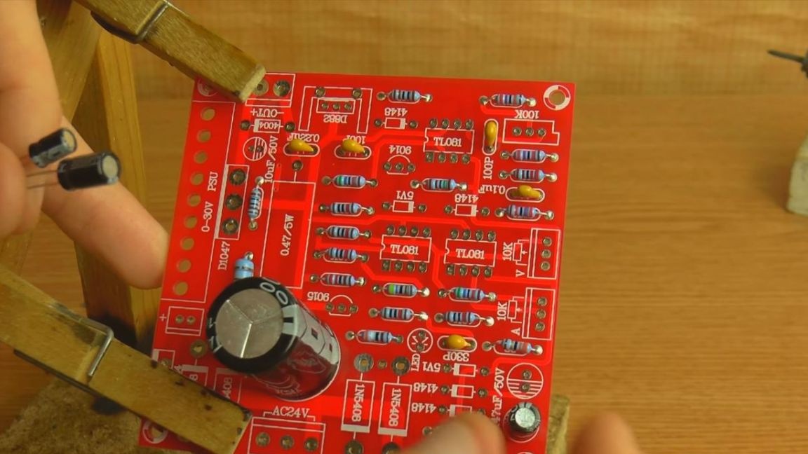
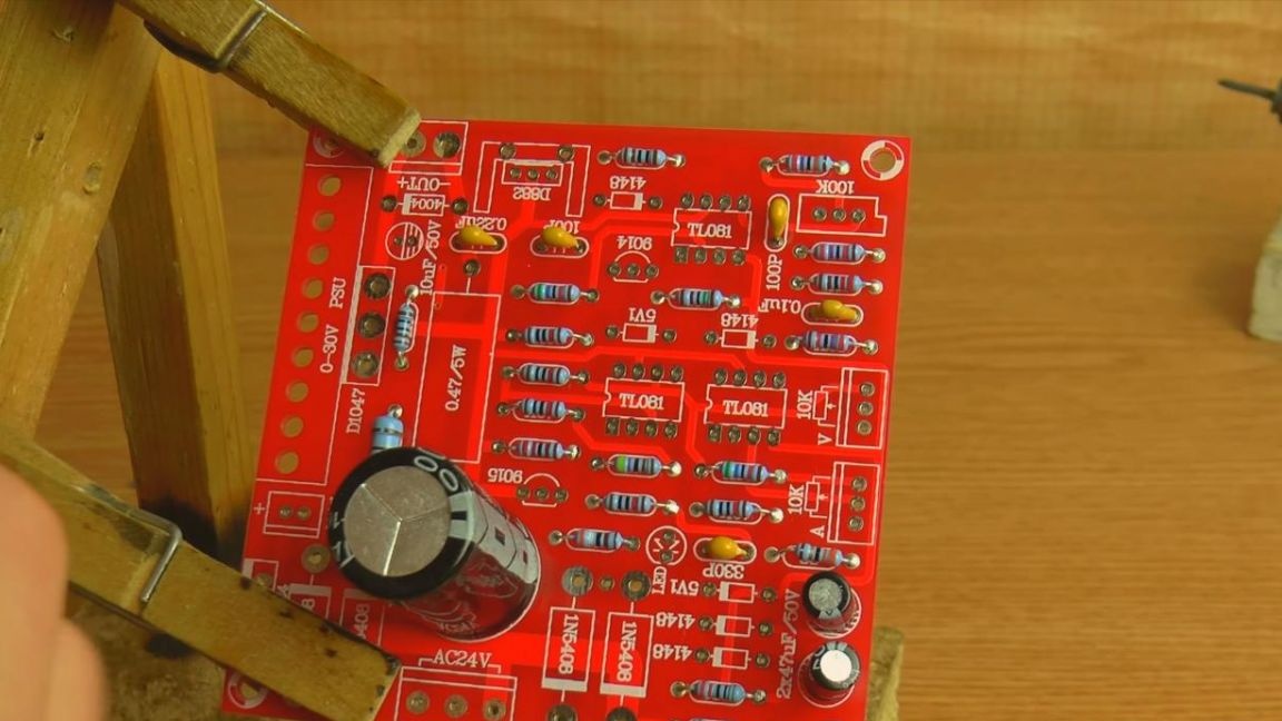
Then we put the electrolytic polar capacitors.
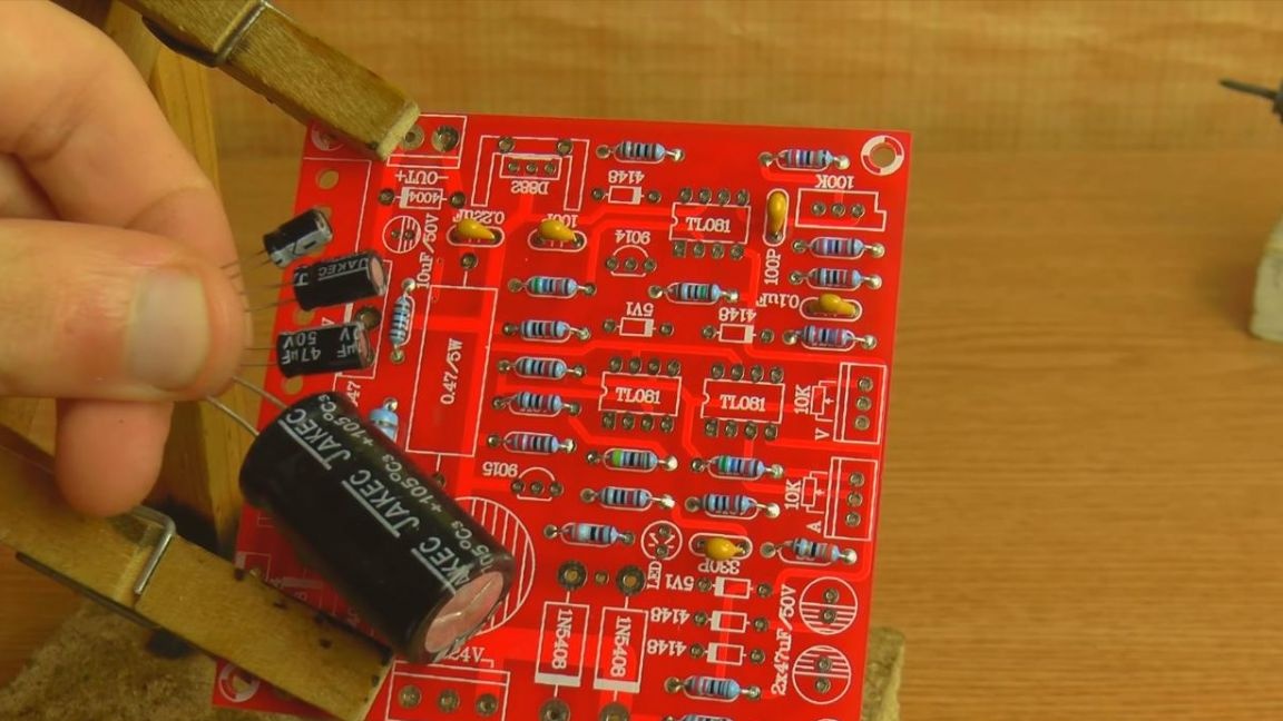
Their denomination is indicated on the case, as well as on the board, but in this case it is also necessary to determine the polarity. The positive terminal on the capacitor is a long leg, short minus, also the location of the negative terminal is marked on the case with a gray strip, and on the circuit board the minus is indicated by a shaded semicircle.
Step Five
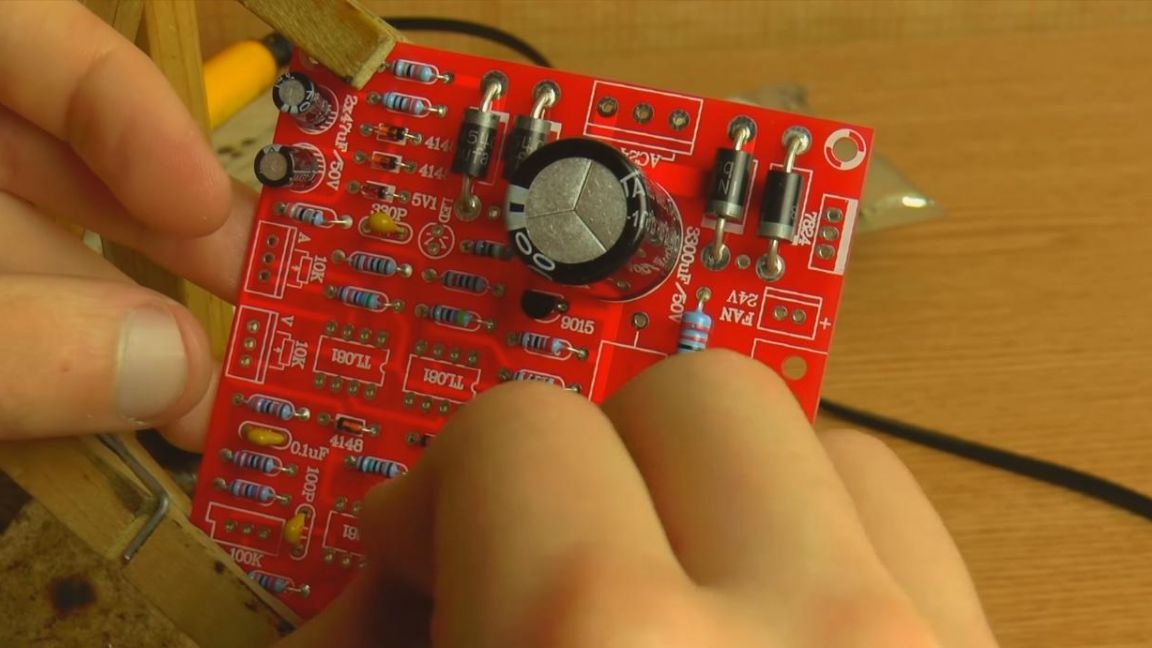
Now it's time for diodes and zener diodes.
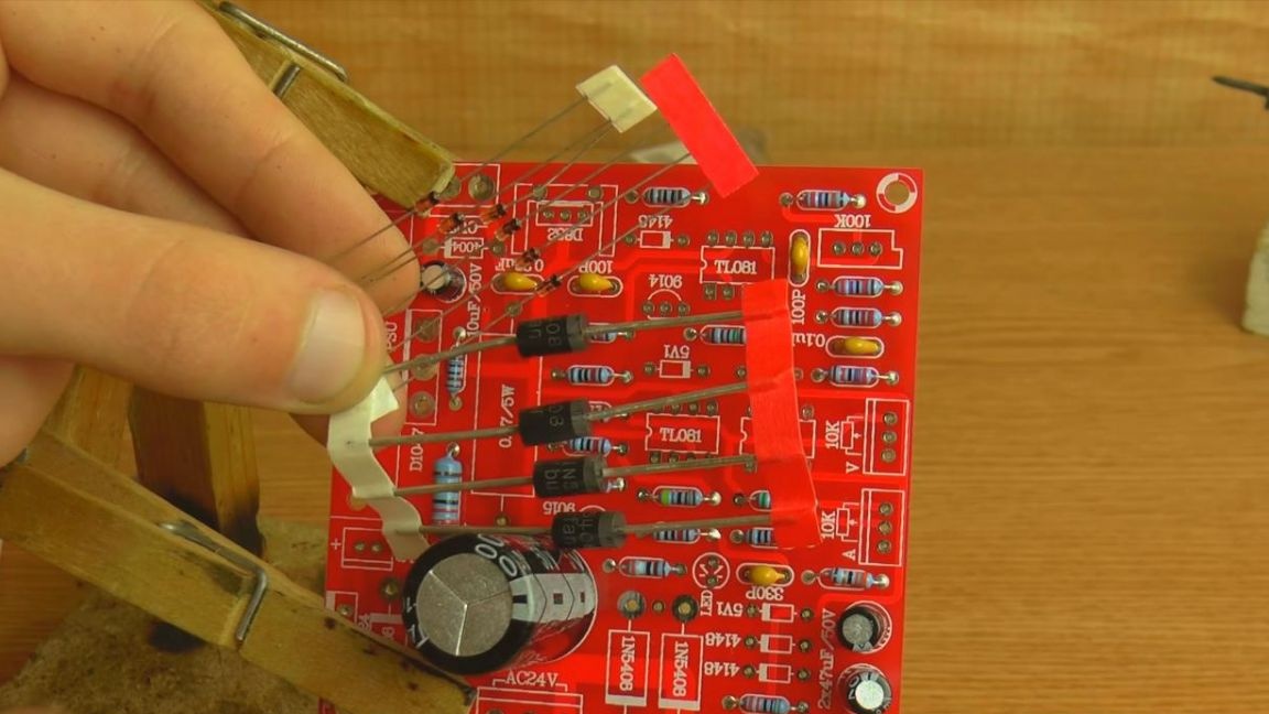
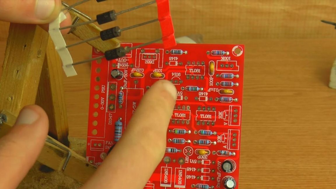
There are strips on their cases, which are also indicated on the board in white.
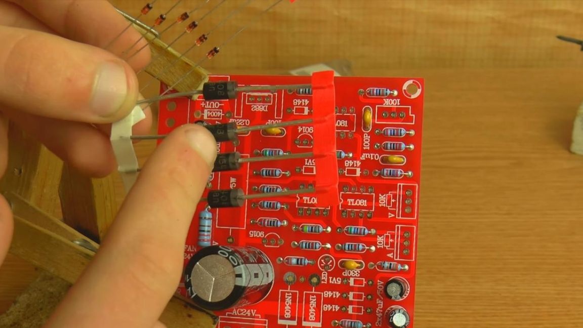
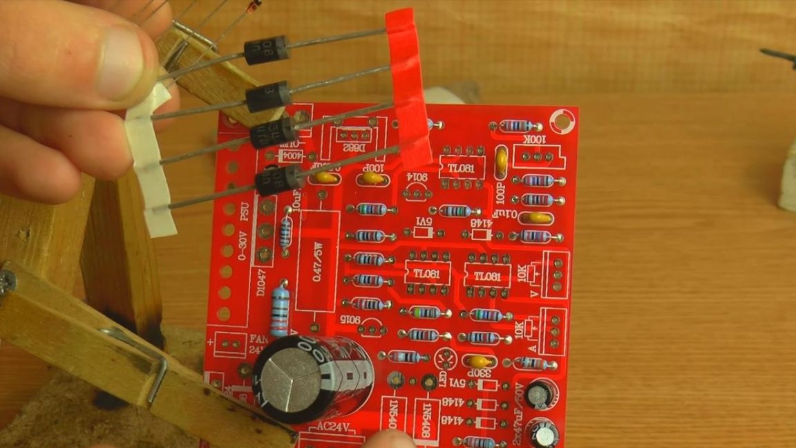
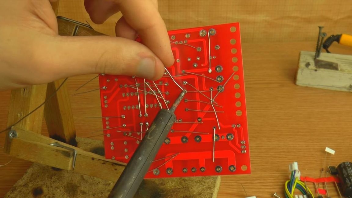
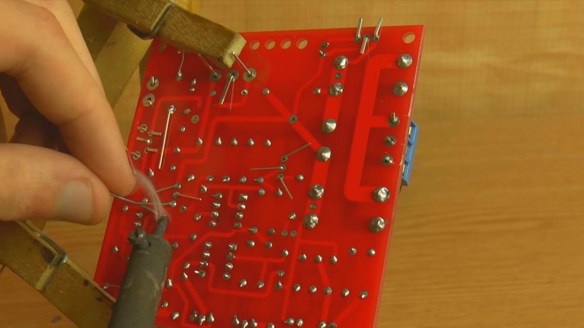
After installation, we solder the parts to the board, prematurely bending the leads so that the components do not fall out when soldering.
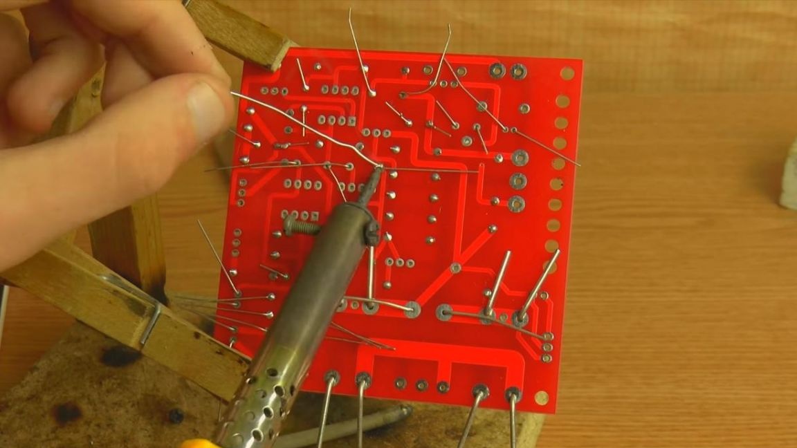
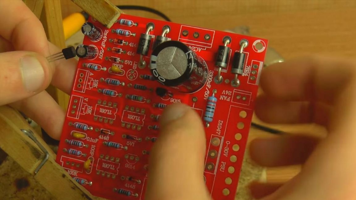
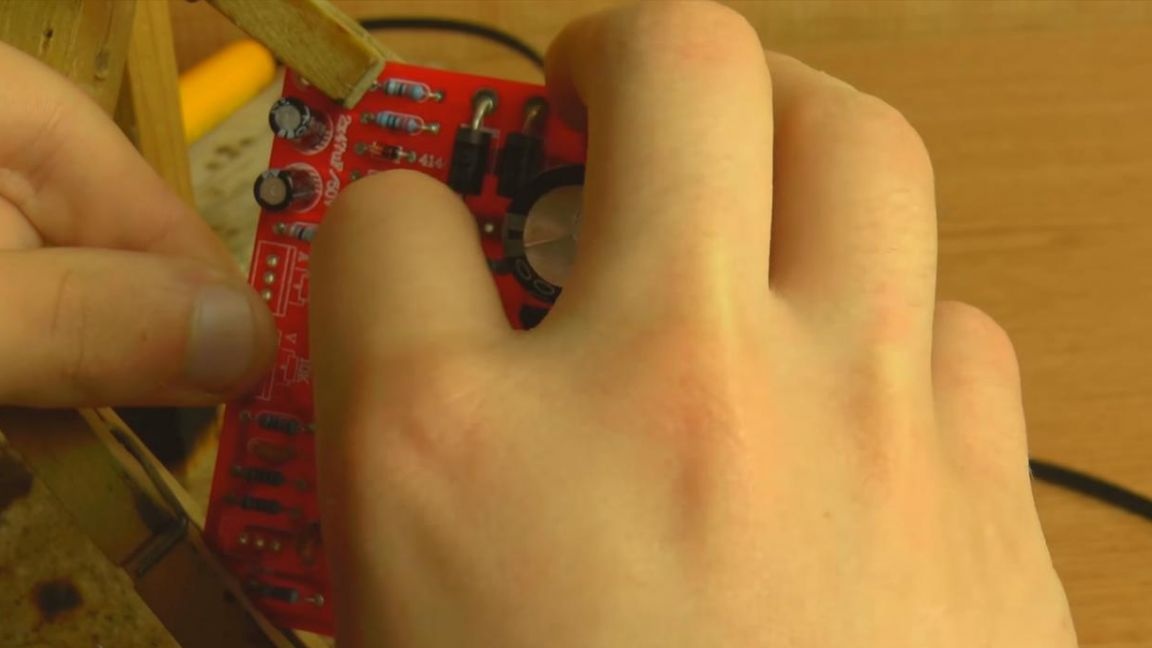
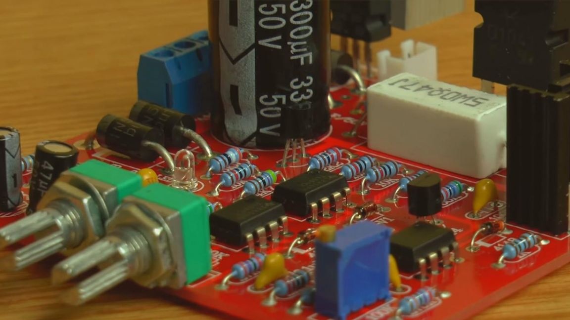
We install transistors on the board, their case has the shape of a semicircle, which is also shown on the board, we combine them, and in order not to confuse each other, both the case and the board are digitally marked.
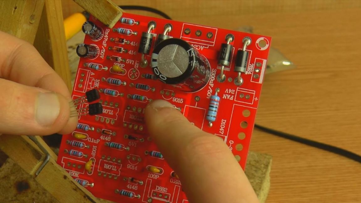
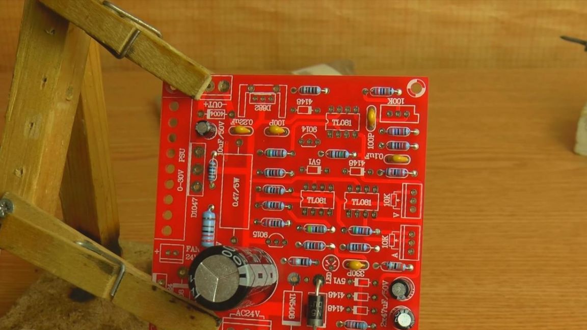
Step Six
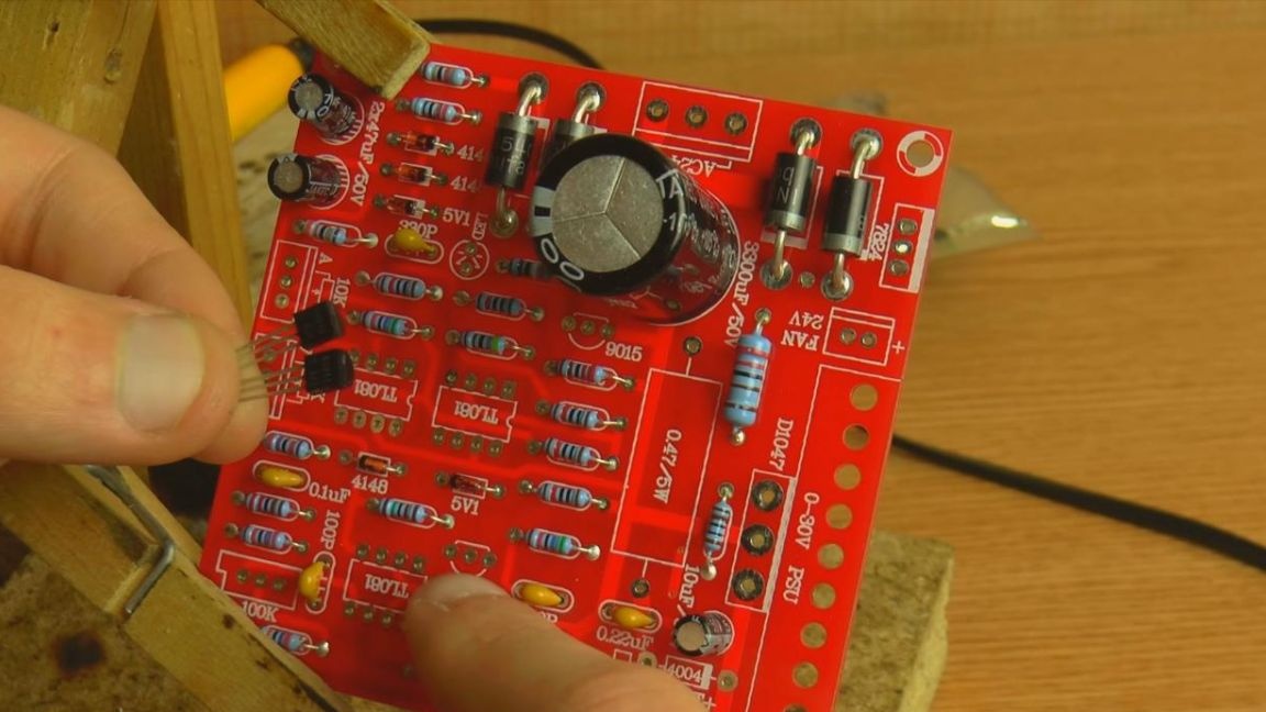
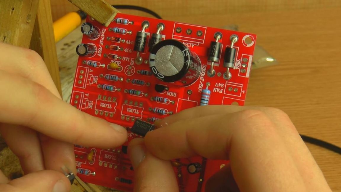
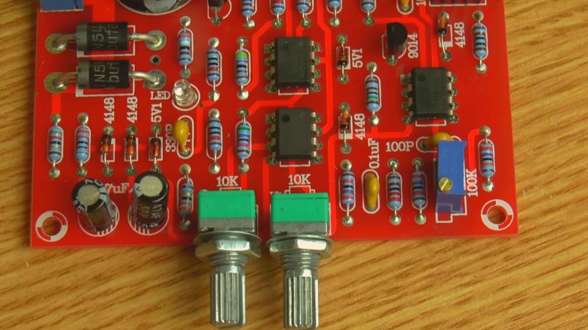
Transistors in place, go to the chips. There are three of them here, and all are the same.
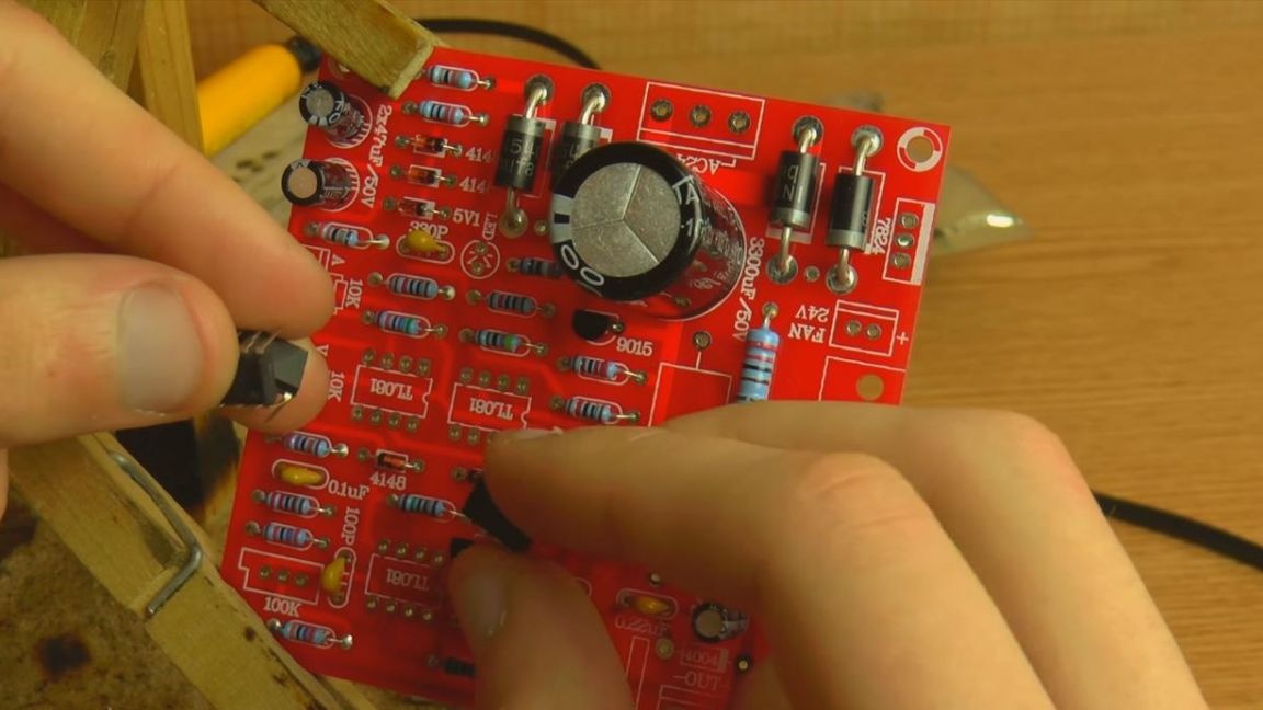
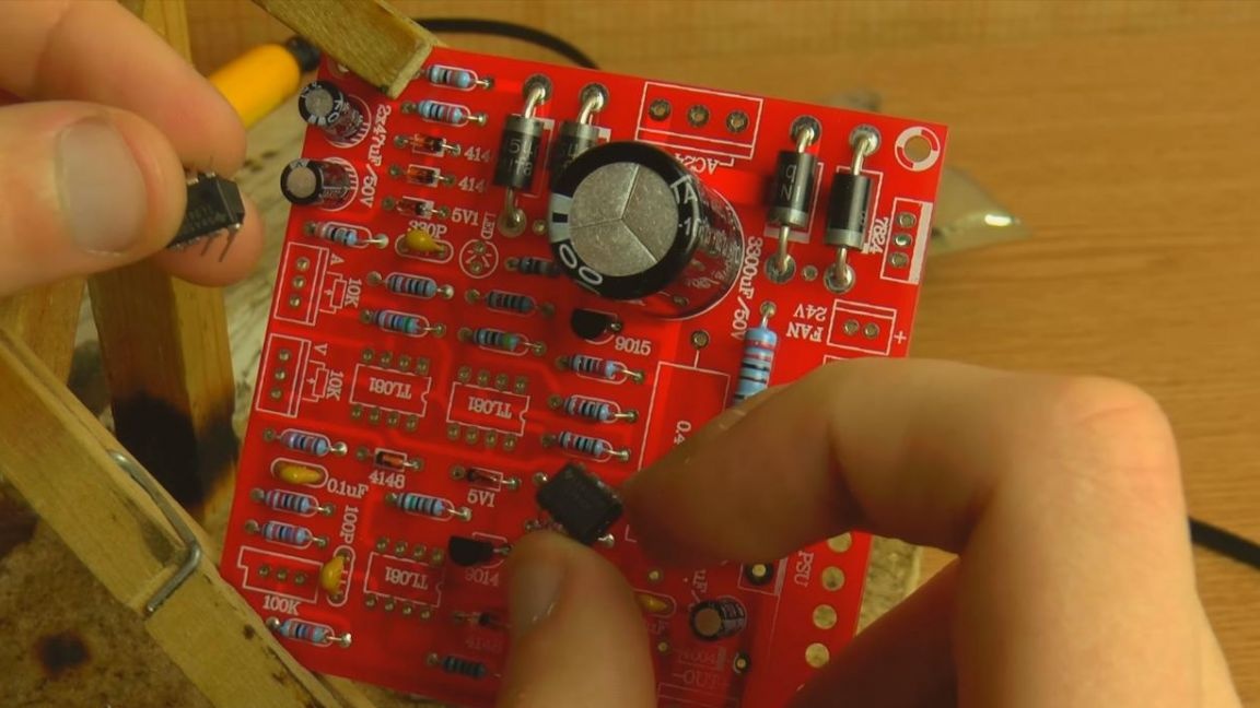
The correct location corresponds to the combination of the key on the chip in the form of a round recess or a point with the key on the board, and on the side of the first output on the board, the contact is square.
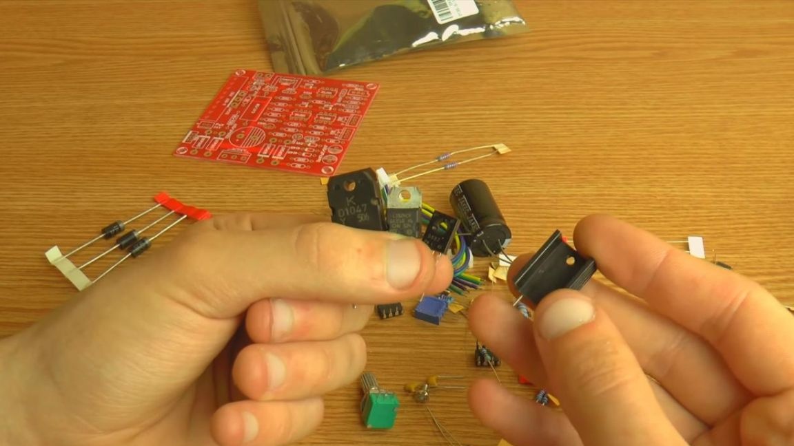
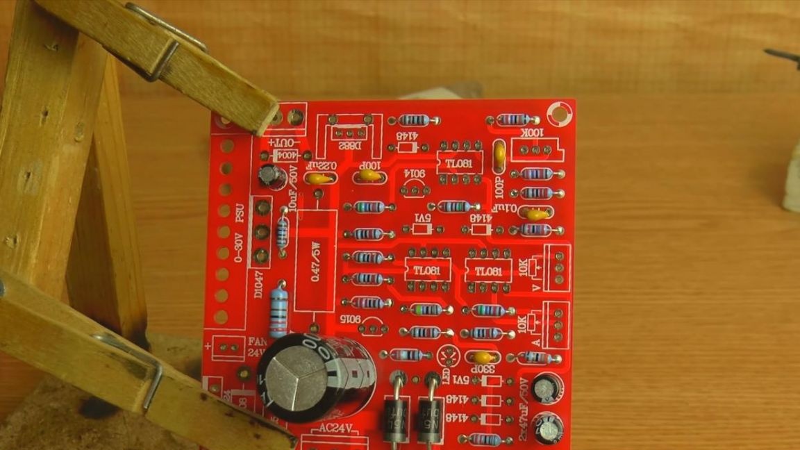
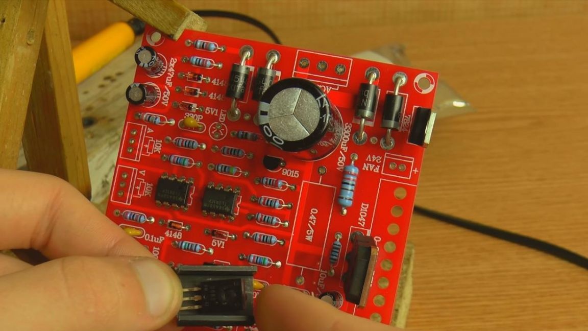
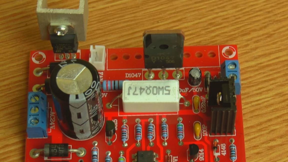
Now we put two large transistors and one voltage regulator, since they are signed on the board, and there is an inscription on their case, it will be difficult to mix up.
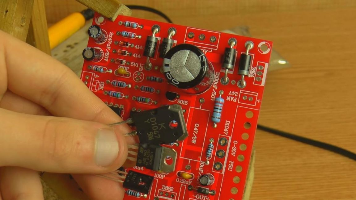
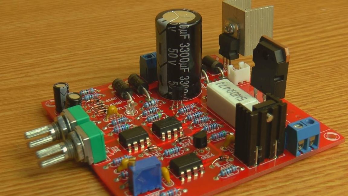
We fasten the aluminum radiator with a screwdriver to the D882 transistor to remove heat.
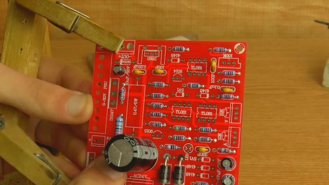
Seventh step.
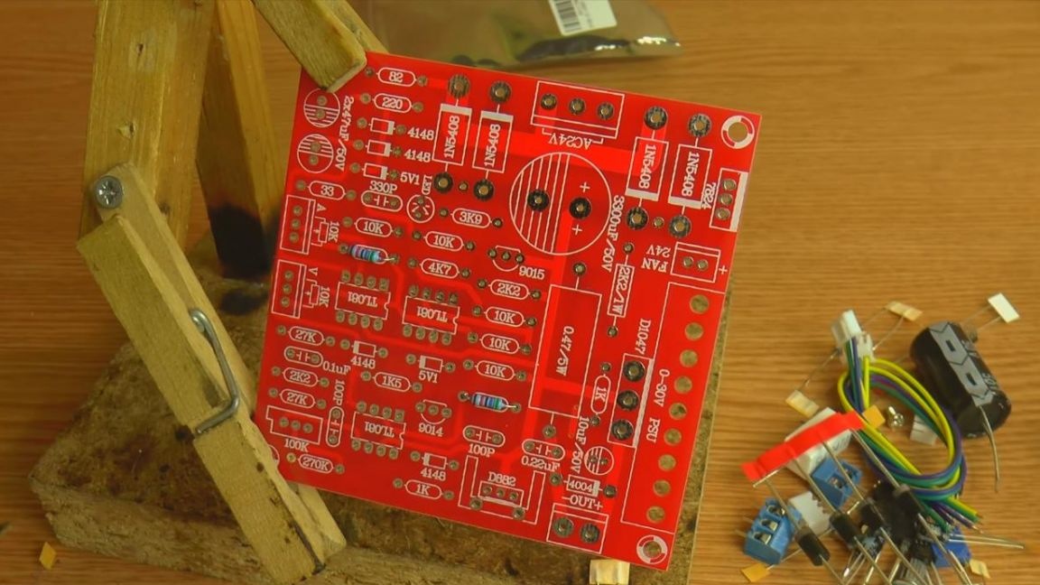
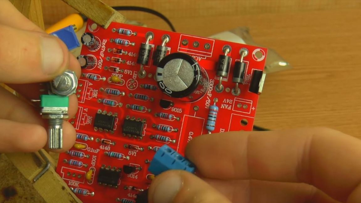
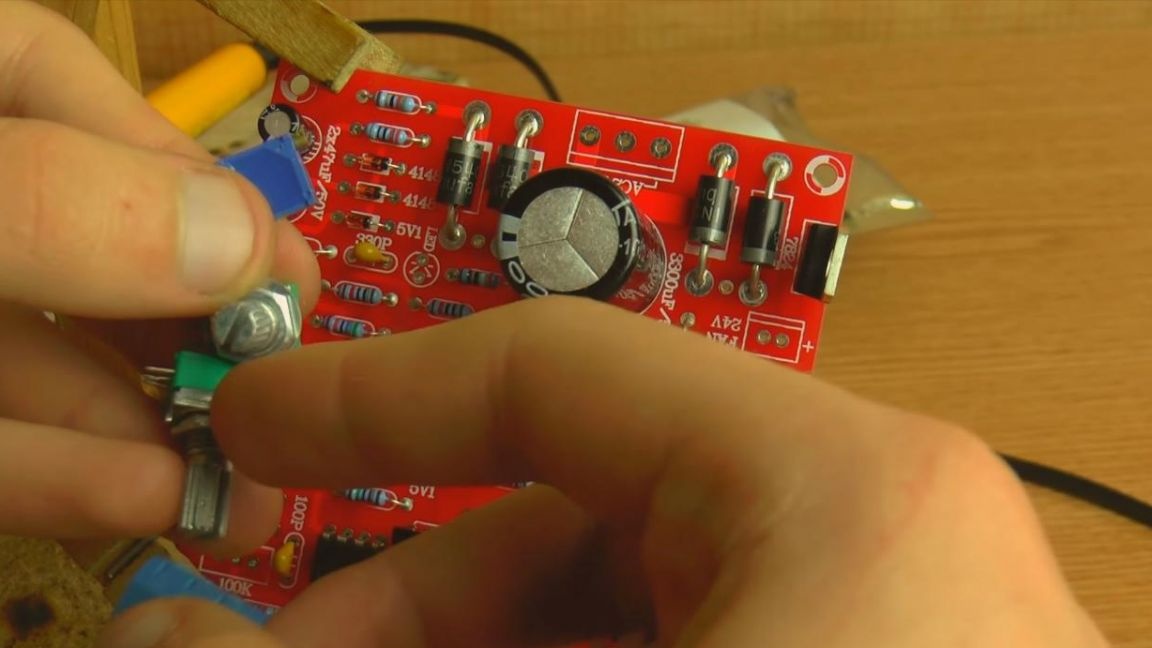
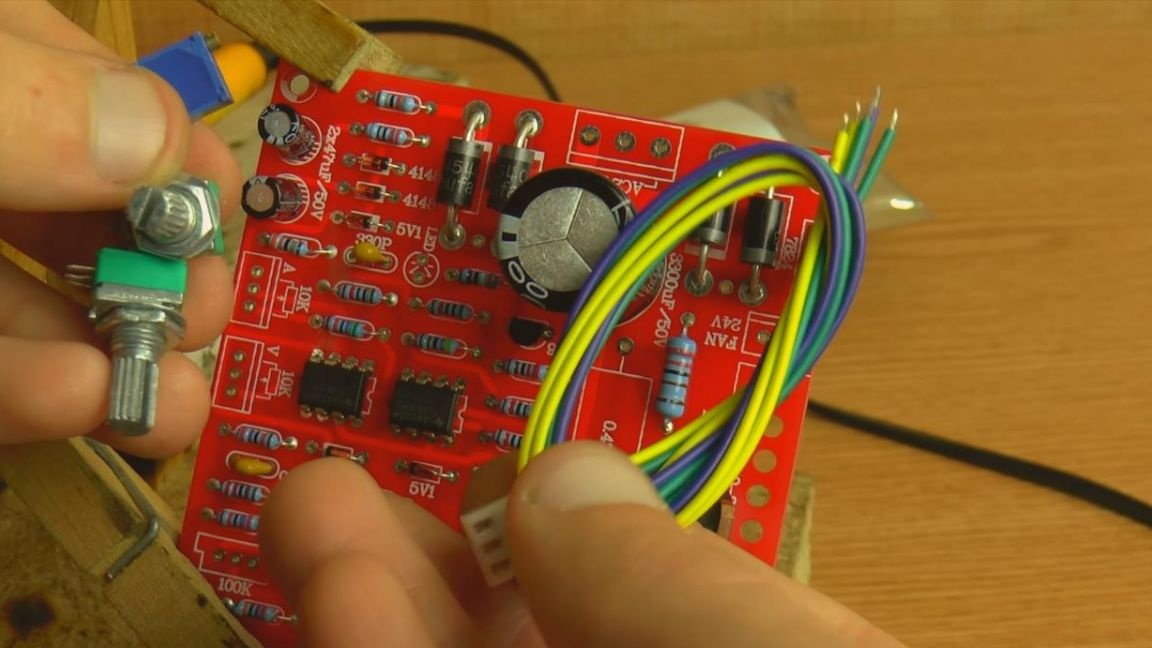
It remains just a little bit, it’s to set the variables, tuning resistors, the first also included the pieces of wire that you need if you need to move the resistors to another location, regardless of the board, as well as pads for connecting the wires as an output, so and power input.
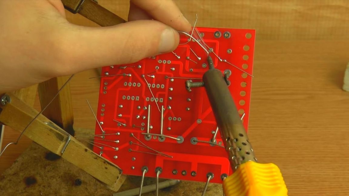
Step Eight.
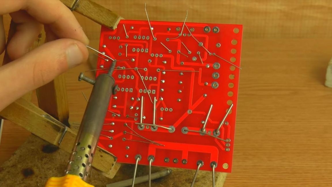
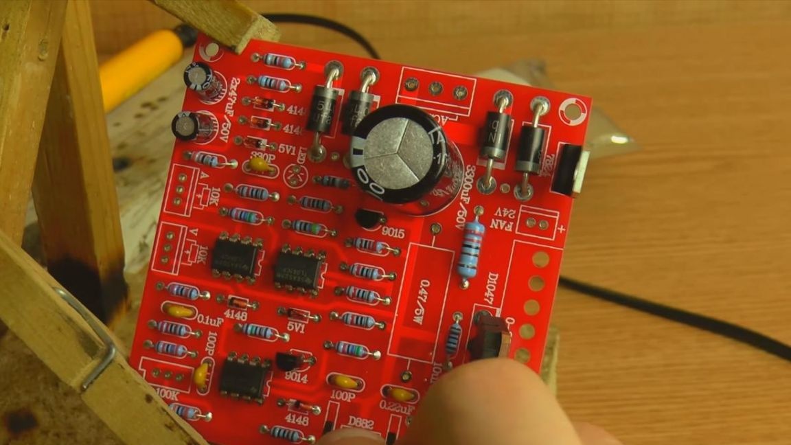
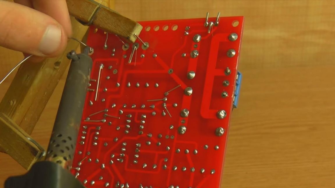
Solder all the installed parts on the board, bite off the extra parts of the leads with side cutters and proceed to testing the device.
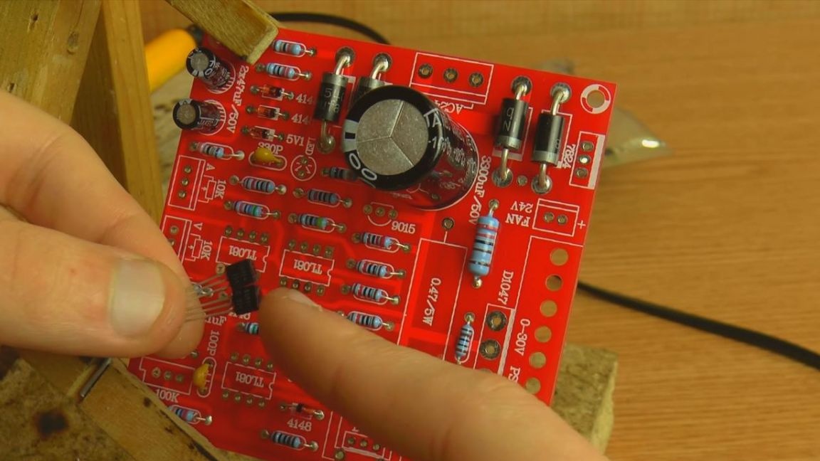
But before that, do not forget to install the missing cooling radiators, as if the parts are heated under loads, which means that the generated heat must be removed from them, otherwise they may fail. Screws were also put in the kit, possibly for fixing the same radiators or installing the board in the case.
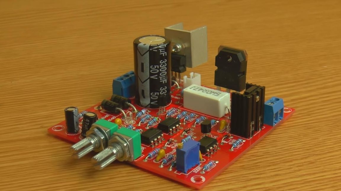
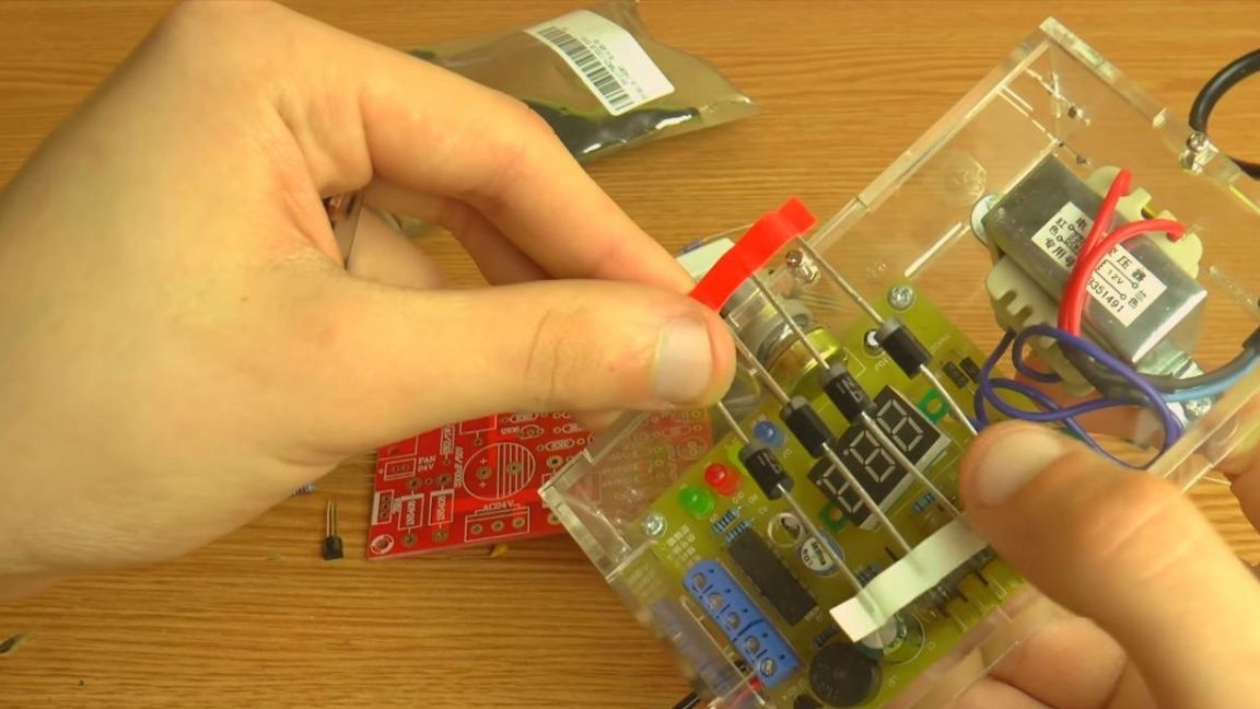
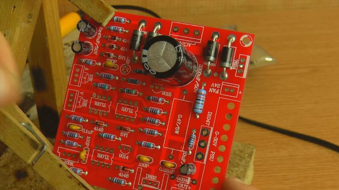
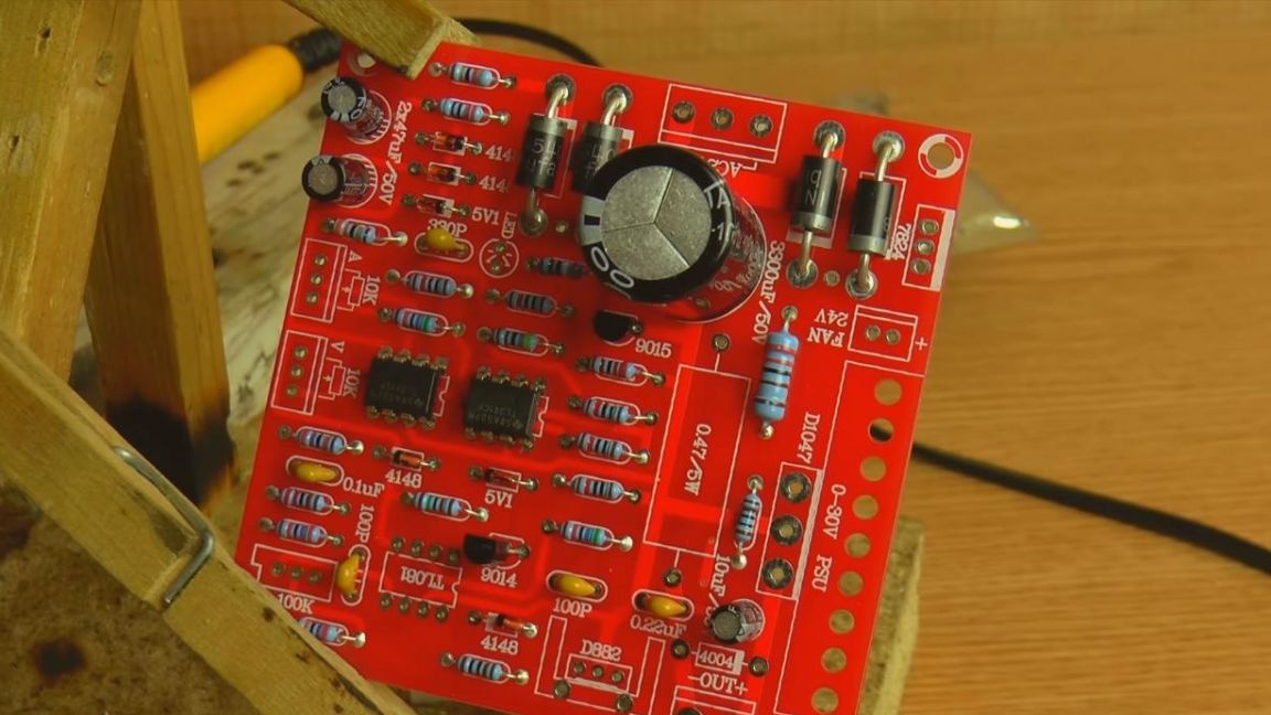
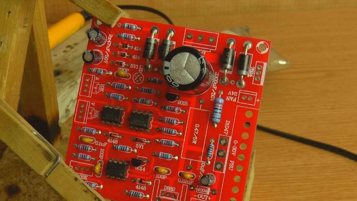
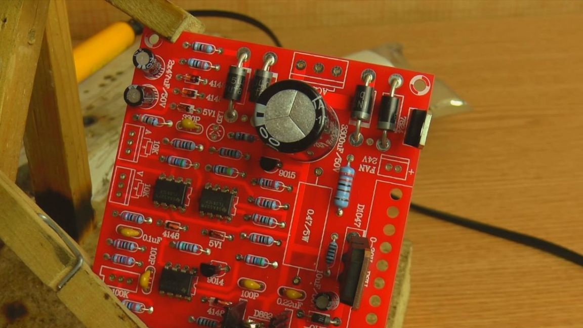
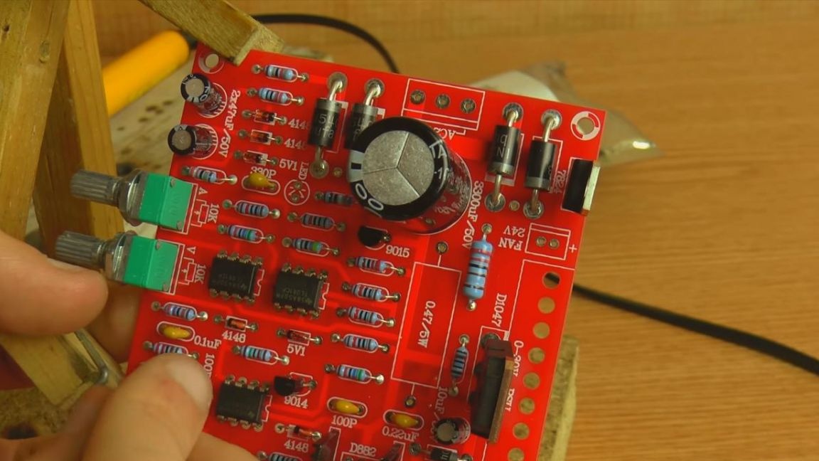
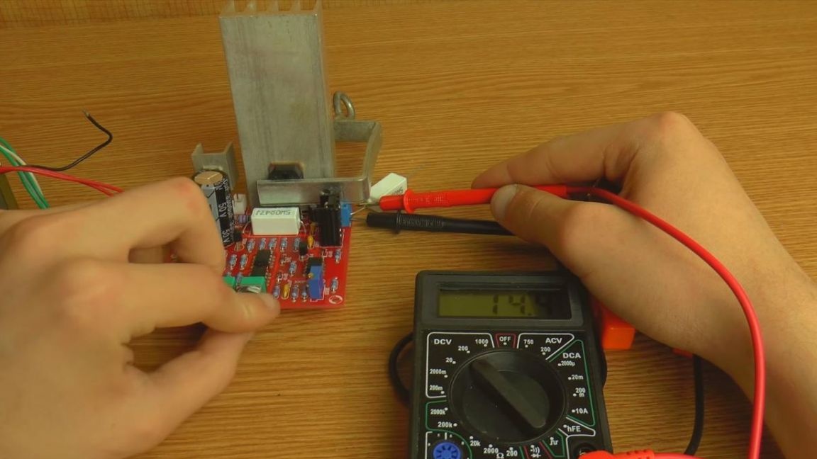
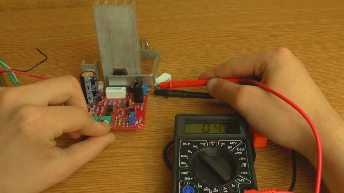
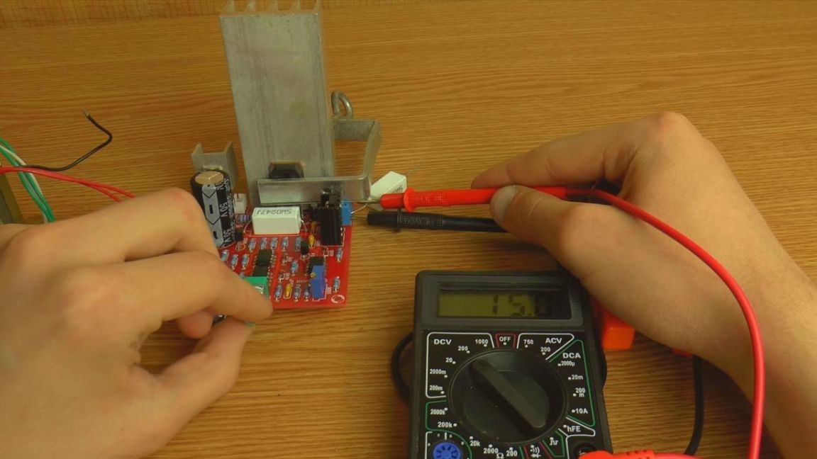
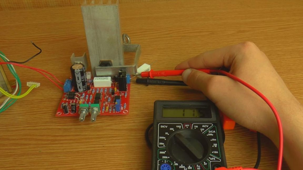
This is how a finished, self-made laboratory power supply looks like.
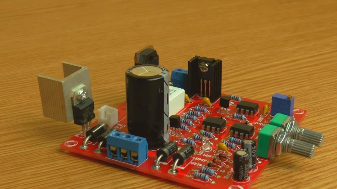
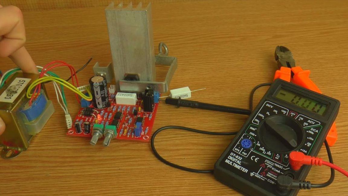
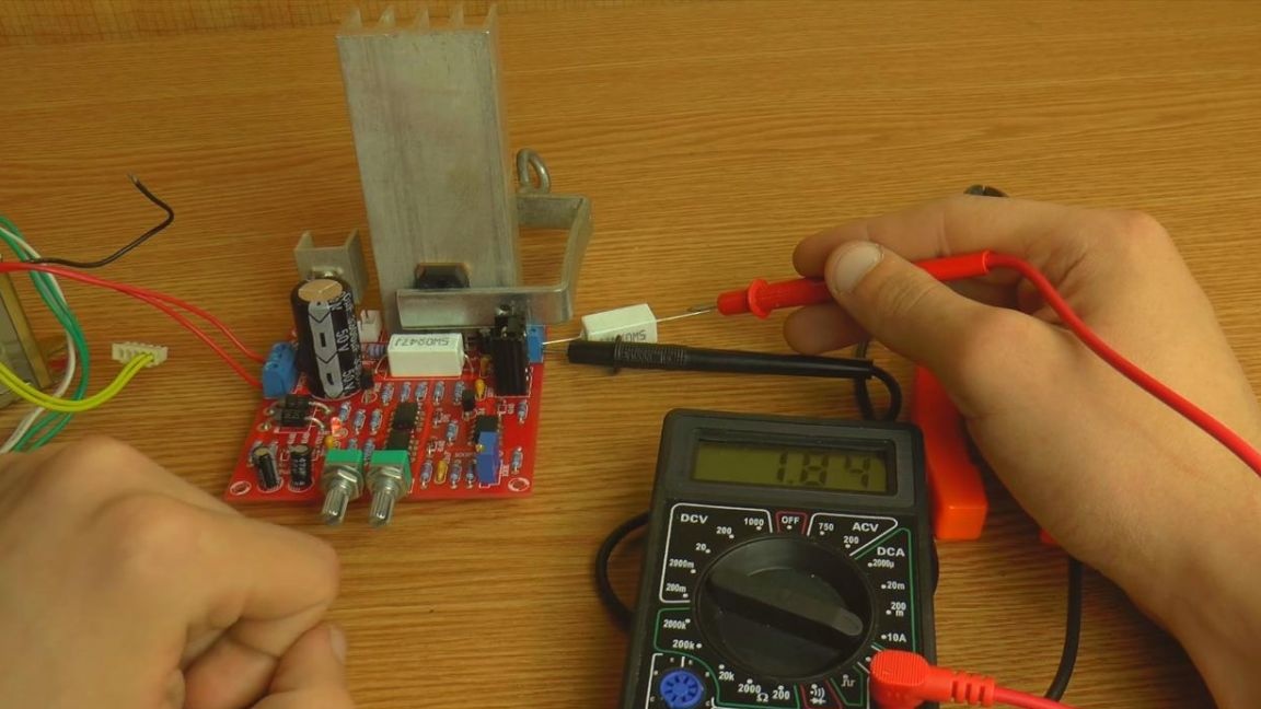
We connect a transformer to the input, in this case it was found only at 16 V and with a current strength of up to 2A, but for verification it will completely work. At the output, we get an adjustable current strength, as well as voltage. With voltage, this adjustment range is 0 - 30 V, and with a current of 2 mA - 3 A.
That’s all for me. This laboratory power supply can be supplemented with a beautiful case, for example, made of aluminum and add an indicator of current and voltage.
Thank you all for your attention and creative success.