Water in human life is the most important element, not without reason, when developing a site, one of the paramount tasks for the owners is to provide water. Both drinking and technical. Well, in general, in any subsidiary farm, the task of storing water in containers and manipulating it is very common. This task is quite simple, arises with high frequency. Given that storage and emptying tanks are usually not located in the most accessible place, it is very useful to automate these processes.
There are countless devices of varying complexity and fortune, for this kind of purpose. A host of them can be roughly divided by the type of sensors - the most tender and vulnerable part of the machine.
The simplest devices are with contact sensors, like buttons. Obvious disadvantages - it is difficult to make this kind of sensor reliable and durable - it is supposed to work under conditions of very high humidity, the design contains more or less accurate moving elements. The machine itself, as a rule, is simple.
The next obvious solution is the use of proximity sensors, to which, conventionally, electrodes dipped into water can also be attributed. With obvious advantages - the reliability of the sensors, we have a much more complex and capricious, including in the configuration, scheme. Often, for reliable operation of the circuit, the water must be of constant quality (up to temperature).
As a kind of circuit with contact sensors is the use of sealed contacts as mechanical sensors of reed switches. At the same time, the water level sensors are quite reliable - the moving parts are rough and massive, the tightness of the electrical part is also easy to ensure. Control circuits are very simple and do not require complex setup. The sensor, as a rule, is a magnet on a floating base and several fixed reed switches nearby.
The proposed scheme is with reed switches as sensors. The circuit is reliable, not complicated to configure, and is not demanding on the accuracy of elements. Allows you to automate both the collection of water in the tank, and automatic pumping from it (drainage). The machine has a manual mode. The element base of the device is simple and widely available.
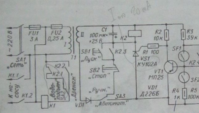
Take a look at the device diagram. The elements are simple, only the contactor K1 is valuable, the rest can be picked from the electric - electronic trash.
Consider the operation of the circuit.
Both reed sensors SF1 and SF2 are included in the base circuit of the transistor VT1. The closure of the reed switch SF2 serving as a sensor of the lower water level causes the transistor to close, when the reed switch SF1 - the upper level sensor closes, the transistor opens. The thyristor circuit VS1 - relay K2 is powered by a pulsating current from the rectifier on the diode VD1. The thyristor opens after the transistor opens. In this case, the relay K2 is activated, the contacts of which connect the winding of the magnetic starter K1 to the network.
In the "Automatic" position of the SA3 switch, the node operates automatically, and in the "Manual" position it can be controlled manually by starting the pump motor by pressing the SB1 “Start” button and stopping it with the SB2 “Stop” button. The introduction of the SA2 switch made it possible to ensure the operation of the machine in the "water rise" and "drainage" modes.
During automatic operation of the unit in the “water rise” mode in the absence of water in the tank, the reed switch SF2 is open, the transistor VT1 is closed. Closed contacts K2.1 enable the magnetic starter K1, so the pairs of contacts K1.1 and K1.2 of the starter are closed - the pump is turned on, water enters the tank. As soon as the float rises above the reed switch SF2, it will open, but the transistor will remain closed, and the pump will continue to fill the tank with water. When the water level reaches the upper mark, the reed switch SF1 closes, the transistor VT1 opens and then the thyristor VS1. Relay K2 will operate and contacts K2.1 will turn off magnetic starter K1 - the pump will stop.
At the same time, the assembly self-locks with K2.4 contacts. Therefore, when the water level in the tank decreases and the reed switch SF1 opens, the transistor VT1 remains open. It will close at the moment the SF2 reed switch closes, and the pump will turn on and the process of filling the tank with water will begin.
In the "Drainage" mode, the pump turns on with a full tank, and turns off when the SF2 reed switch closes. Capacitor C1 smooths the ripple of the rectified voltage, preventing vibration of the armature of the relay K2.
It is recommended to use KEM-2 reed switches in the unit. Relay K2 - REN18 (passport PX4.564.702). Magnetic starter K1 - PML - 1000 for current up to 10A. The transformer is made on the Sh9h30 magnetic circuit. The network winding contains 5000 turns of PEV-2 wire 0.08 mm, secondary - 280 turns of PEV-2 wire 0.5 (its alternating voltage at idle is 13.5 ... 14 V). Resistor R4 to increase the clarity of the operation of the machine should be reduced to 100 ... 200 Ohms [1].
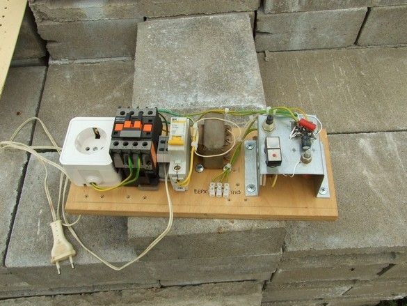
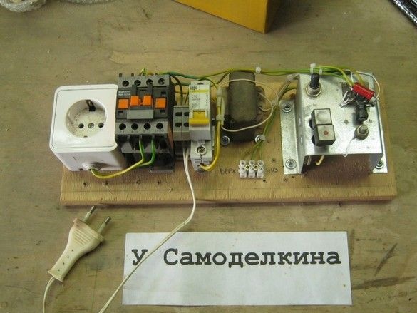
The submachine gun was assembled in a great hurry (hot) on a piece of plywood and from the most waste parts and elements. There was an urgent task to automate the selection of water from an improvised tank with a modest debit.
What was needed for work.
Tools, equipment.
The plywood base was sawn on a circular saw, cut to size on the end pendulum saw. A screwdriver was used for installation - drilling and screwing self-tapping screws, a medium power soldering iron with accessories. Scissors for metal. A set of small tools for electrical installation, a hair dryer, construction or special for working with heat pipes. If necessary, a protective coating of a piece of wood - a brush, dishes. For the manufacture of a water level sensor, a set of metalwork and carpentry tools, a small container for preparing concrete, a marking tool, an extruder for sealant came in handy.
Materials
In addition to the radio elements for the manufacture of the machine, a piece of thick plywood for the base, a small piece of galvanized steel, a piece of DIN rail, a mounting wire, nylon ties, fasteners were needed. For the manufacture of a level sensor, I needed a piece of plastic sewer pipe for outdoor installation (orange) with a diameter of 110 mm, a piece of pipe from a polypropylene water pipe, materials for the preparation of concrete, silicone sealant.
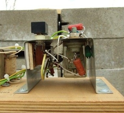
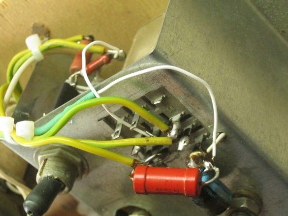
Small installation elements - relays, buttons, thyristor, were fixed on a U-shaped casing, bent from galvanized steel roof, inside, several small radio elements with wire leads were conveniently placed. The relay, in principle, is designed to be installed in a special connector, so I had to solder very carefully. Some elements are mounted directly on it, relays, contacts.
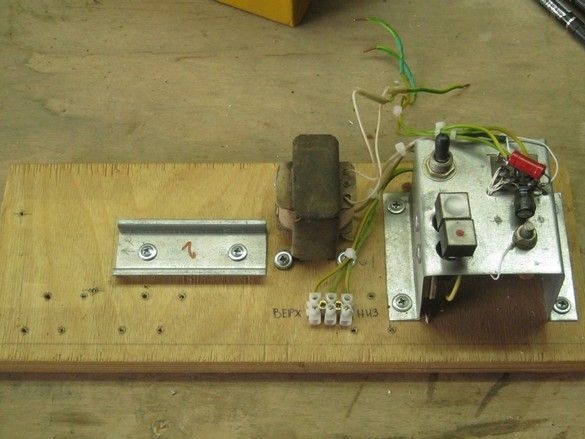
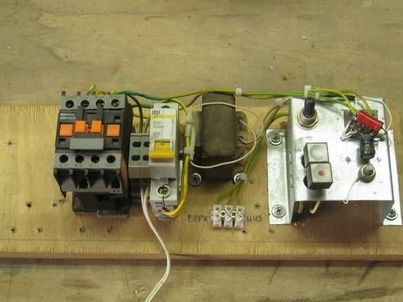
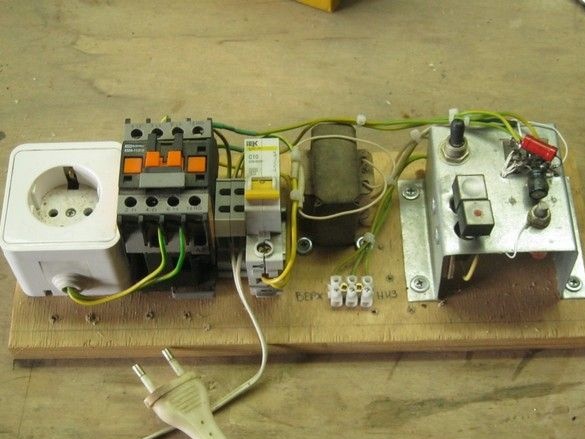
Large installation elements having ears or other fixtures for mechanical fastening, they were fixed with self-tapping screws, a circuit breaker, an intermediate terminal and a contactor, had elements for installation on a DIN rail, a piece of it was involved. The plywood base itself, the board, if necessary, can be supplemented with side walls and a removable (hinged) cover and thus turned into a dustproof box.
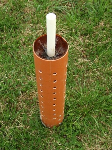
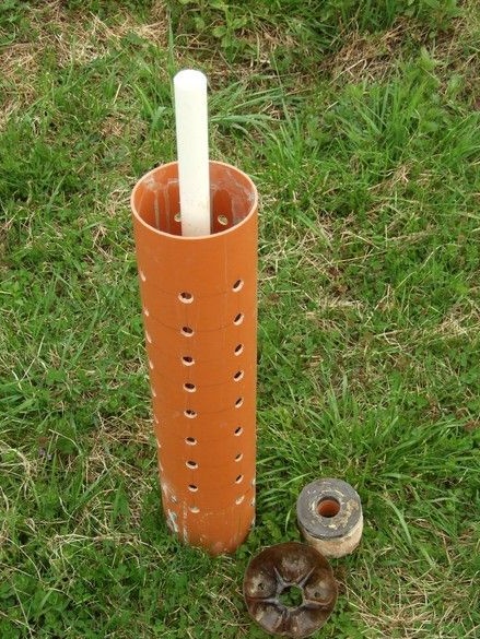
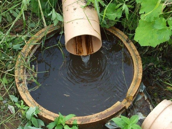
The level sensor was made based on the size of the tank and is a large diameter plastic casing - from a piece of frost-resistant sewer pipe (orange color) with a diameter of 110 mm. For "anchoring" at the bottom of the tank, a concrete load is cast at the bottom of the pipe; in it, coaxially with the casing, a piece of plastic polypropylene pipe is muffled at one end. Reed switches are placed in it. Outside the pipe, on a foam pad-float, an annular magnet floats from the dynamic head. Water flows freely into the casing through many drilled holes. The casing itself protects the magnet on the float from coupling with other equipment of the tank - the pump, its suspension ropes, power cord and hose.
To exclude the loss of concrete cargo from the casing, several long galvanized self-tapping screws with wide caps were screwed into it (casing) before pouring. After concreting, their ends protruding inward, were walled up in concrete.
The float is glued to the magnet with silicone sealant, its best working position is upward with the float, on the contrary - sometimes a heavy magnet warps and wedges on the pipe, but if it floats under the float, it moves smoothly and without jamming behind the water level.
The electrical part of the level sensor - two reed switches with wiring, are placed inside a white “dry” pipe. To the terminals of two reed switches with closing (switching) contacts, mounting wires of the appropriate length (with some margin) are soldered, soldering spots are washed from the flux and sealed. To begin with, with a sweep, in a couple of layers, on top of a thermotube. On the protruding part of the white tube, for each pair of wires, two holes are drilled one above the other. Through them pull the wires from the reed switches. Adjustment of the lower and upper water levels "on site" is carried out by adjusting the length of the reed switch wires.
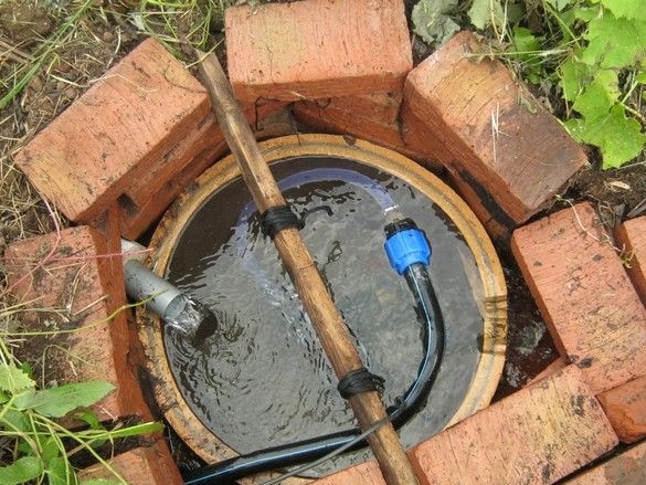
The assembled machine worked only at the stand - the problem of lack of water was solved in the most radical way - by manufacturing a full-fledged capturing chamber. The debit of the spring at the same time increased significantly, so much so that the pump capacity is not enough to draw out the storage capacity. The risk of “draining” the vibrating pump is minimized. The machine, however, is stored and will be used to automate the collection of water in the tank.
1. The journal "Radio", No. 1, 1992 Page 24.25.

