
In this article we will assemble a very simple and fairly reliable soldering station.
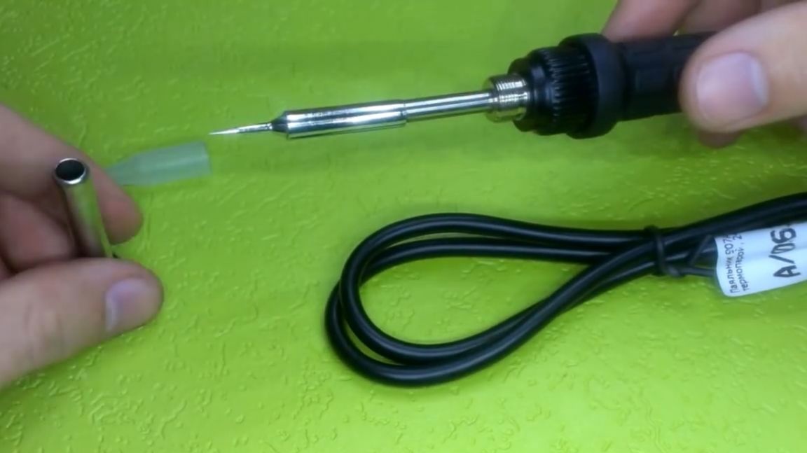
On YouTube, there are already a lot of videos about soldering stations, there are quite interesting instances, but all of them are difficult to manufacture and configure. In the station presented here, everything is so simple that anyone, even an inexperienced person, can handle it. The author found the idea on one of the forums on the Soldering Iron website, but simplified it a bit. This station can work with any 24-volt soldering iron, which has a built-in thermocouple.
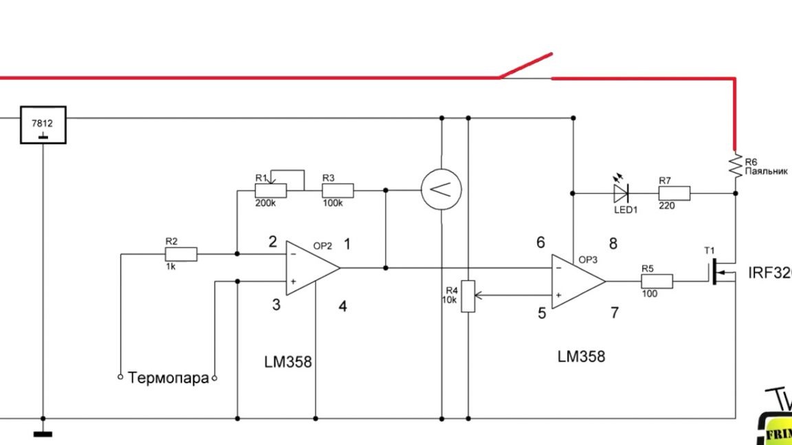
Now let's look at the device diagram.
Conditionally, the author divided it into 2 parts. The first is the power supply on the IR2153 chip.
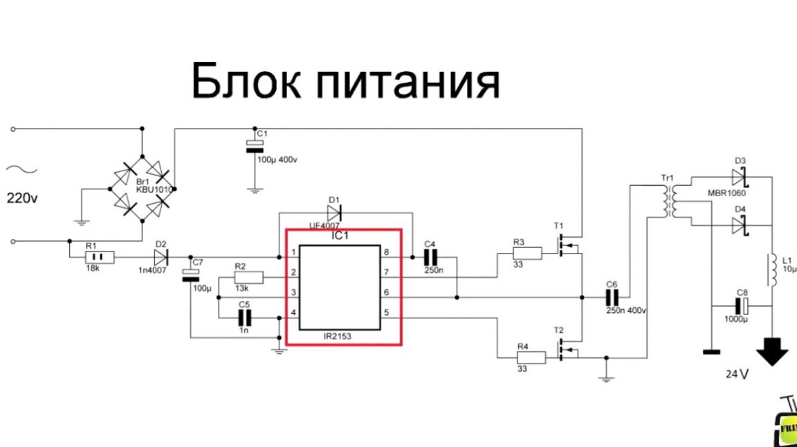
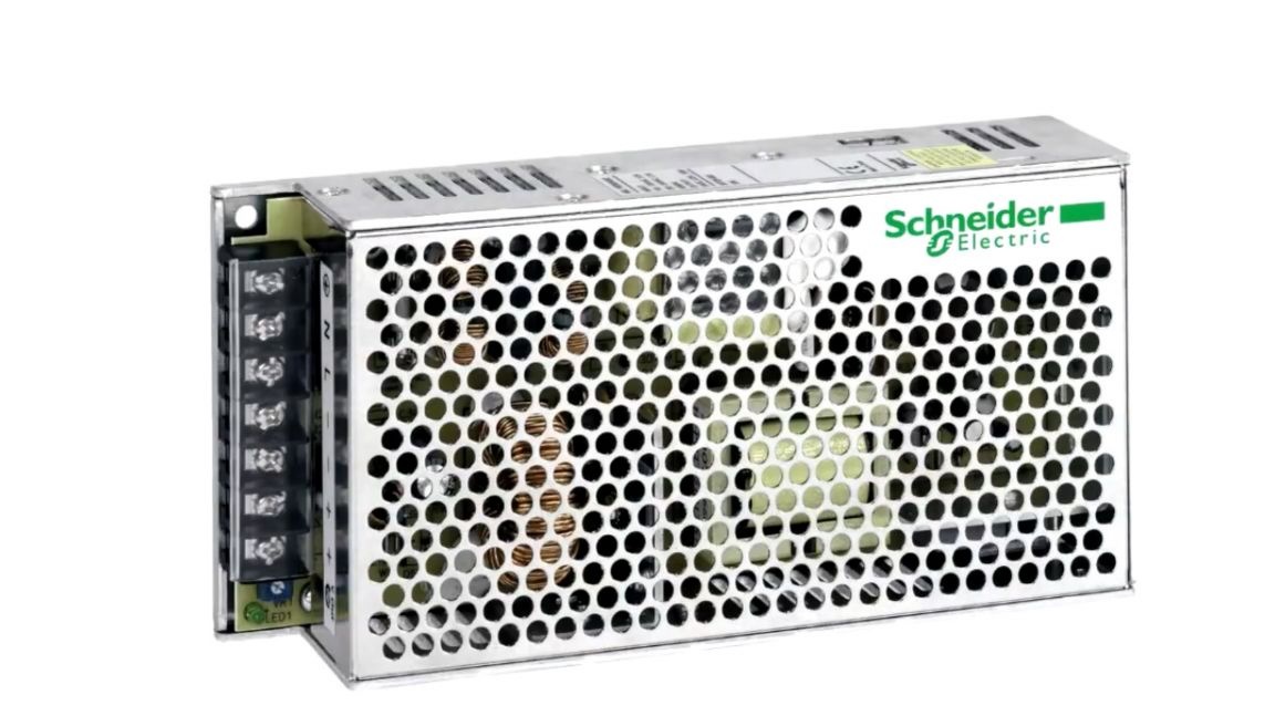
A lot has already been said about her and we will not dwell on it; you can find examples in the description under the author’s video (link at the end of the article). If you are reluctant to mess with the power supply, you can skip it altogether and buy a ready-made copy for 24 volts and a current of 3-4 amperes.
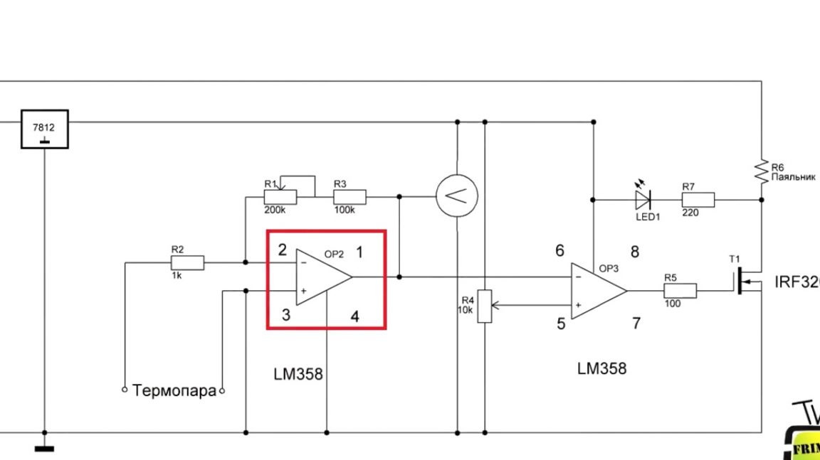
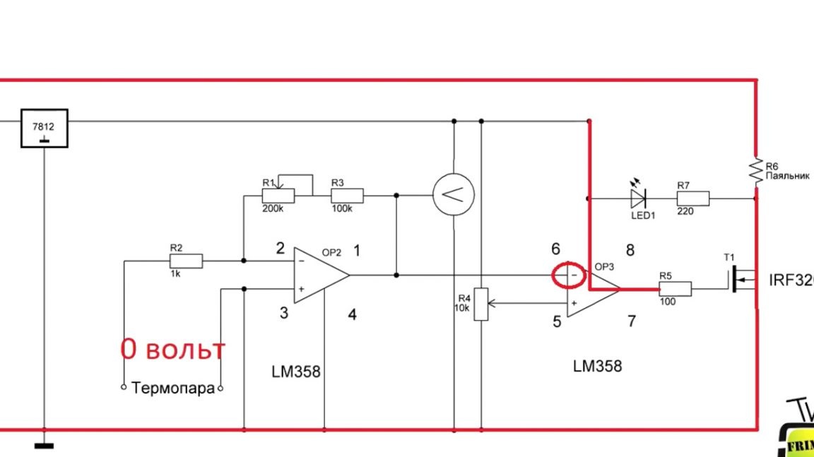
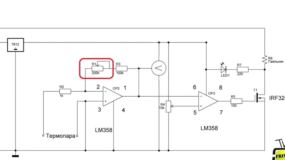
The second part is the actual brains of the station. As mentioned above, the circuit is very simple, performed on a single chip, on a dual operational amplifier lm358.
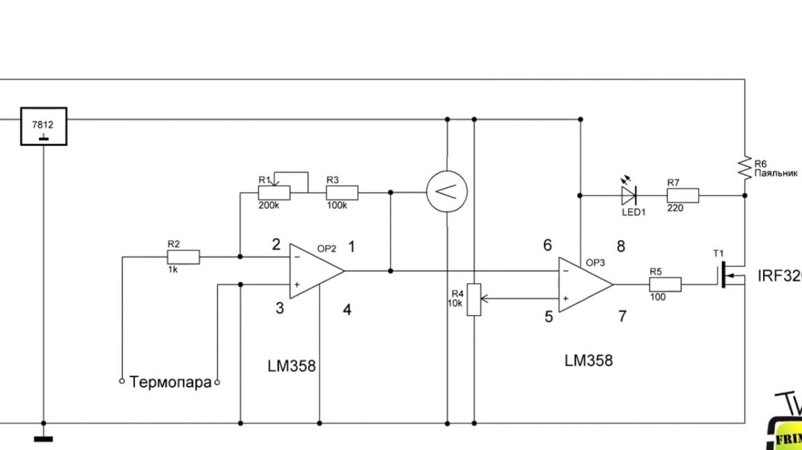
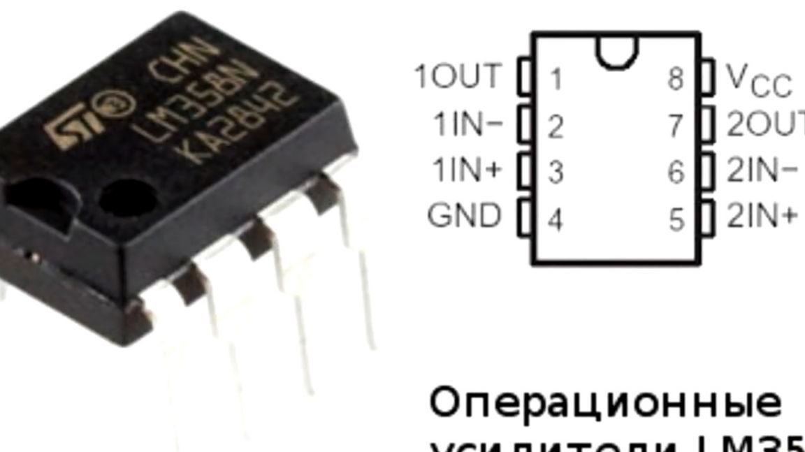
One opamp works as a thermocouple amplifier, and the second as a comparator.
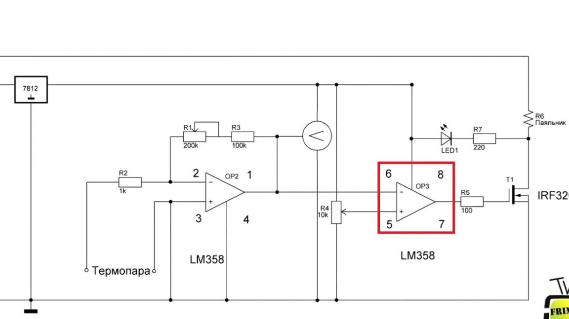
A few words about the operation of the scheme. At the initial time, the soldering iron is cold, therefore, the voltage on the thermocouple is minimal, which means that there is no voltage at the inverting input of the comparator.
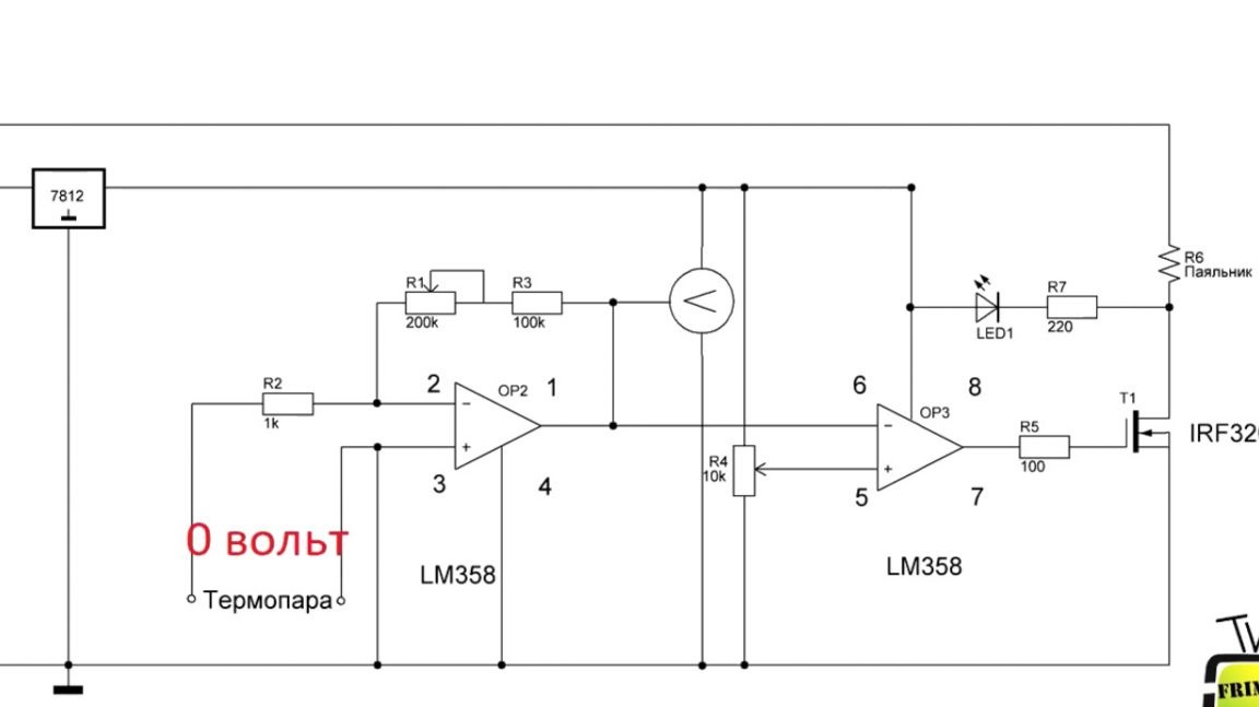
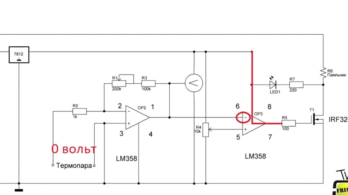
The output of the comparator plus power. The transistor opens, the spiral is heating.
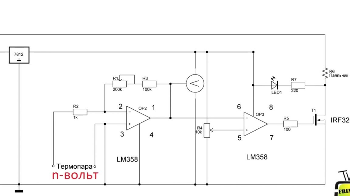
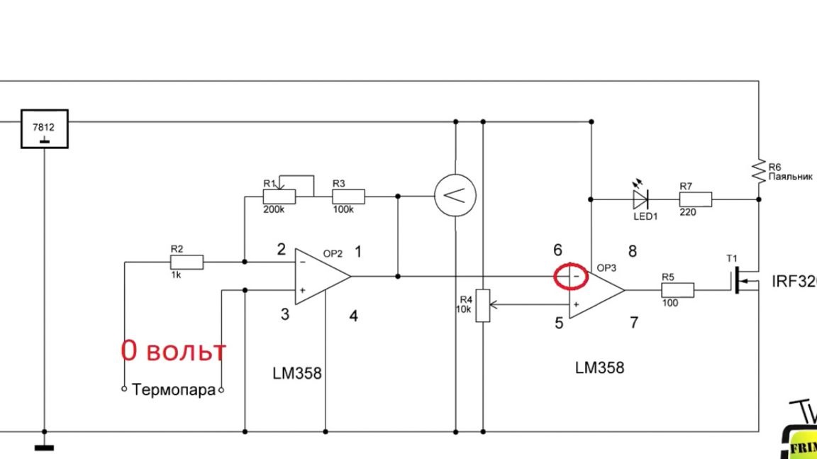
This in turn increases the thermocouple voltage. And as soon as the voltage at the inverting input equals the non-inverting one, 0 will be set at the output of the comparator.
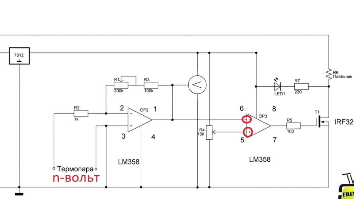

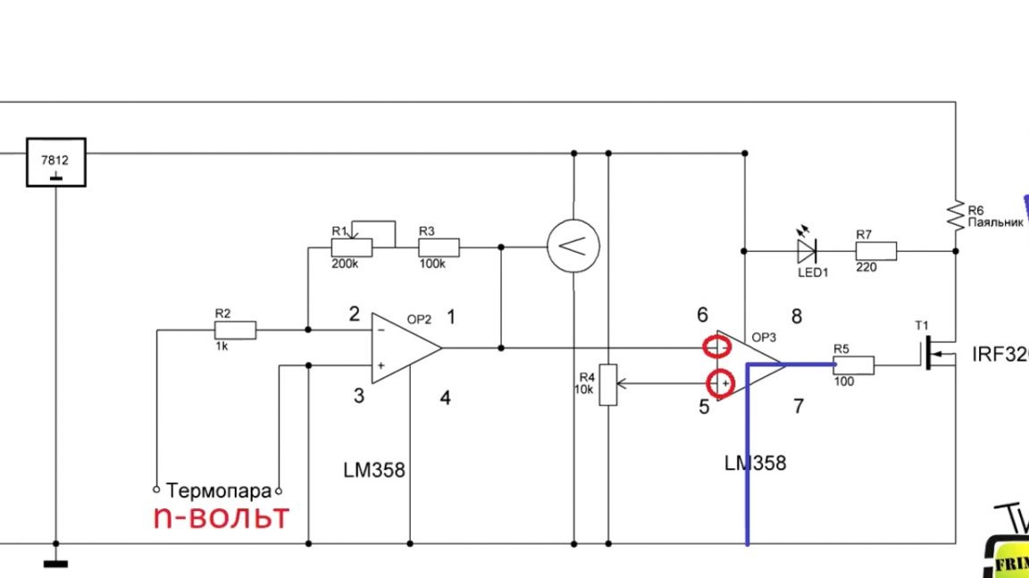
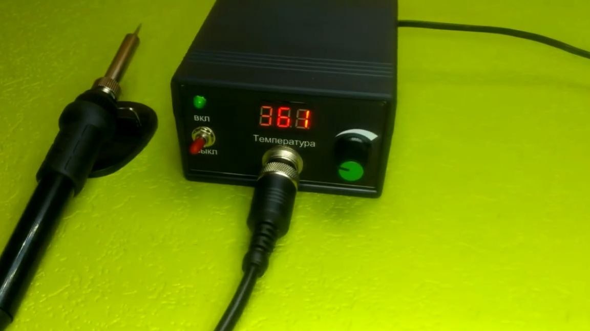
Therefore, the transistor turns off and the heating stops. As soon as the temperature drops by a fraction of a degree, the cycle repeats. Also, the circuit is equipped with a temperature indicator.
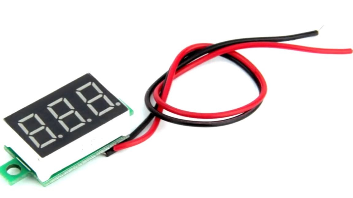
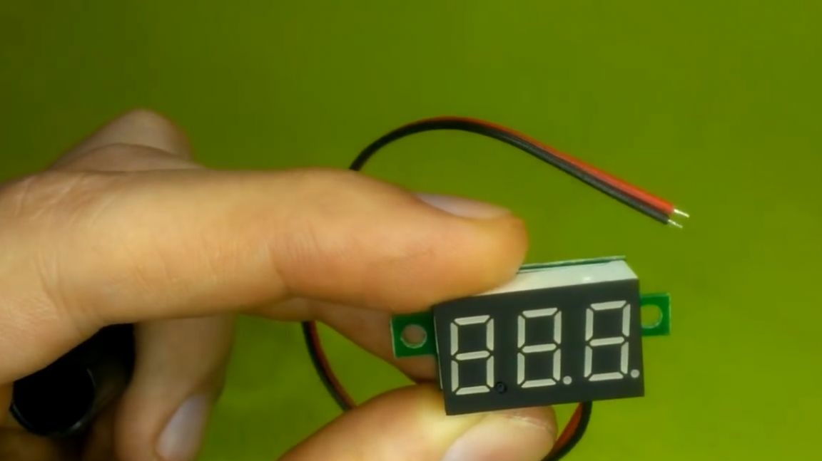
This is an ordinary Chinese digital voltmeter that measures the amplified voltage of a thermocouple. To calibrate it, a trimming resistor is installed.
Calibration can be done using a multimeter thermocouple, or at room temperature.
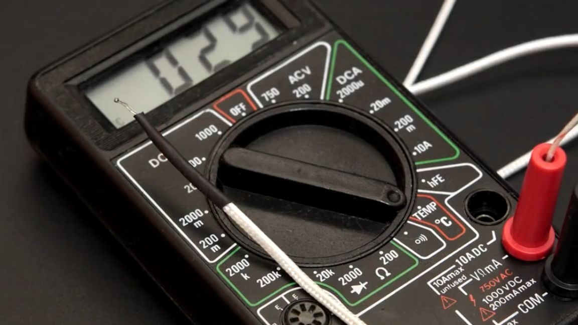
This author will demonstrate during the assembly.
We figured out the circuits, now we need to make printed circuit boards. To do this, use the Sprint Layout program, and draw the printed circuit boards.
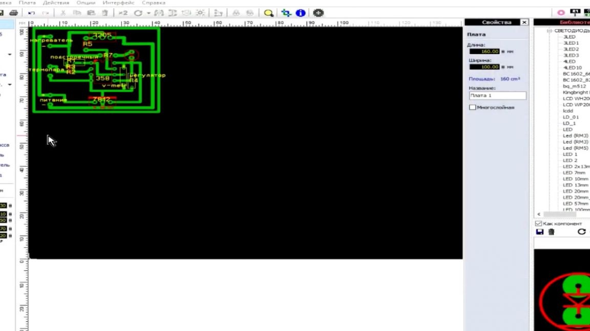
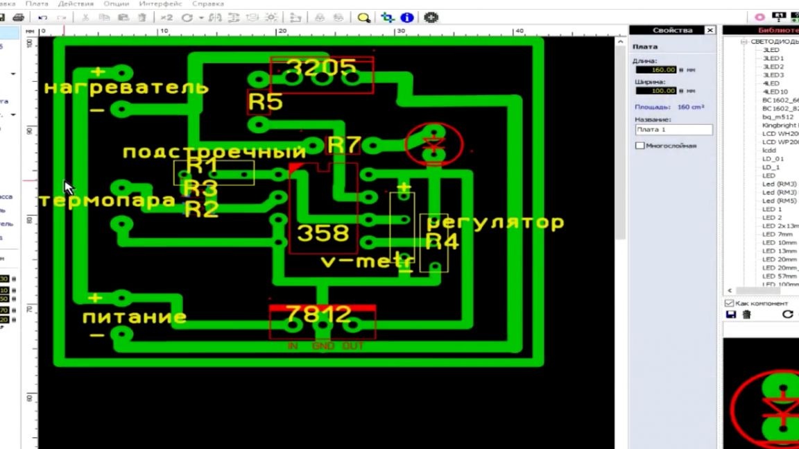
In your case, just downloading the archive is enough (the author left all the links under the video).
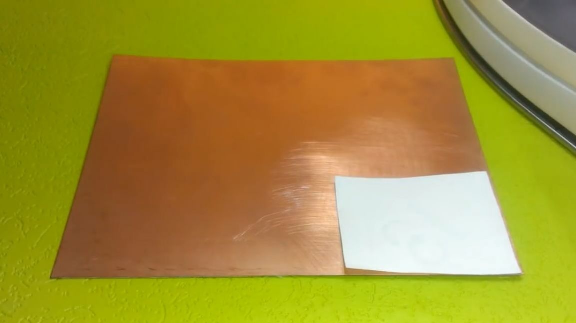
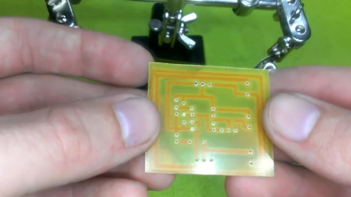
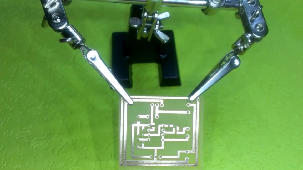
Now we are going to make a prototype. We print the drawing of the tracks.
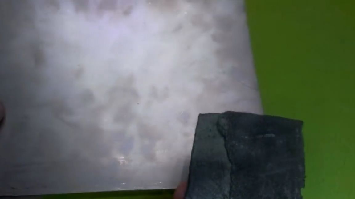
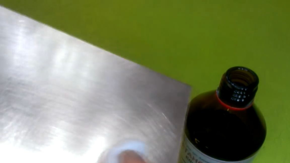
Next, we prepare the surface of the PCB. First, with the help of sandpaper, we clean the copper, and then with alcohol we degrease the surface to better transfer the pattern.
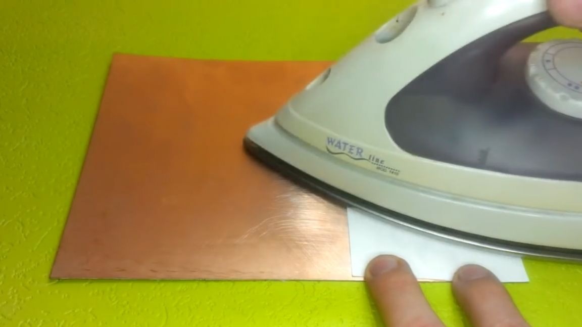
When the textolite is ready, we place the board pattern on it. We set the maximum temperature on the iron and go through it on the entire surface of the paper.
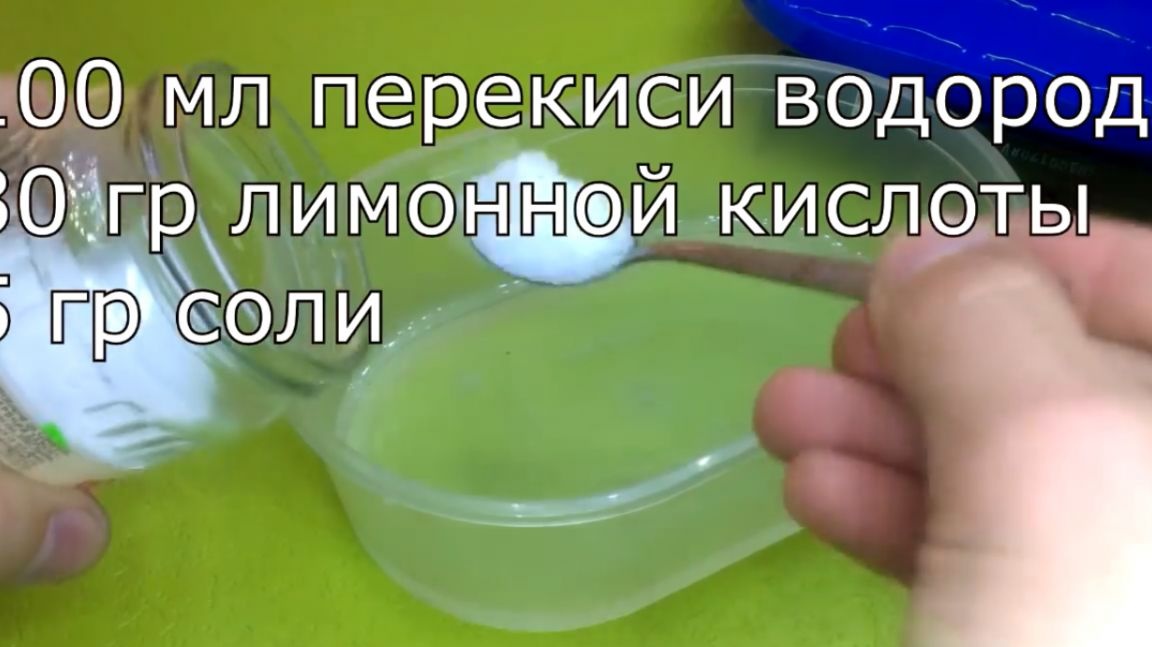
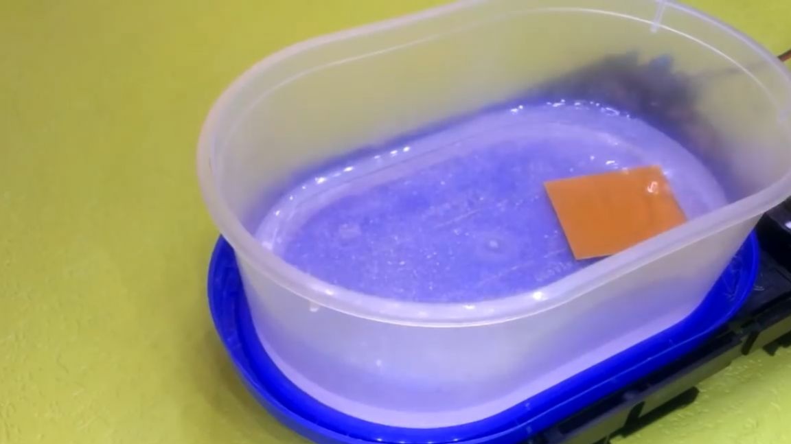
Everything, you can start etching. To do this, prepare a solution in the proportions of 100 ml of hydrogen peroxide, 30 g of citric acid and 5 g of sodium chloride.
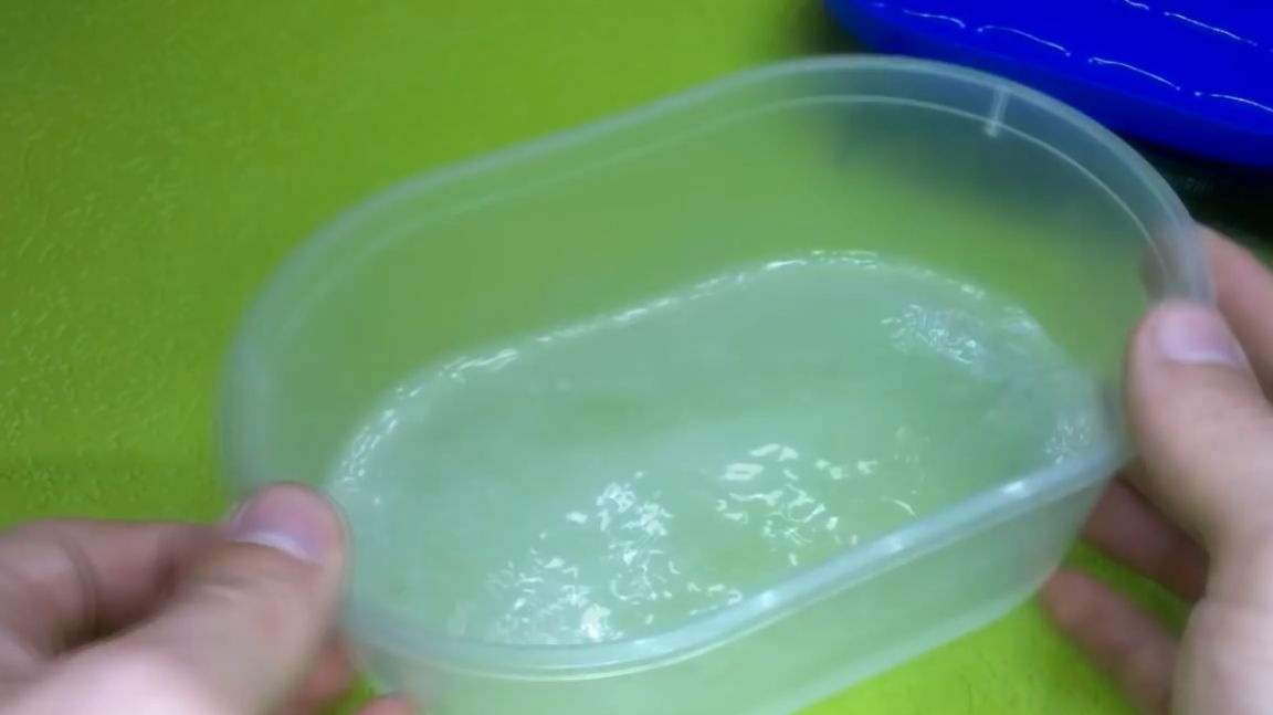
We put the board inside. And to accelerate the etching, the author used his special device, which he collected do it yourself earlier.
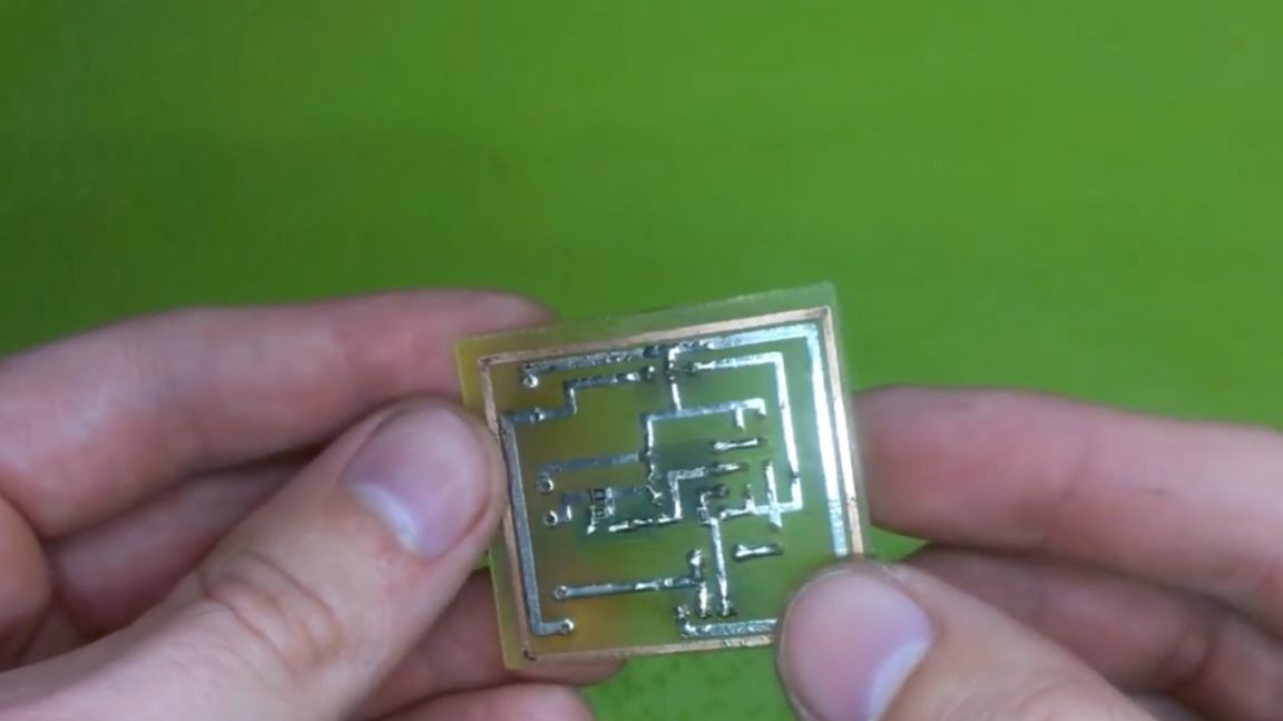
Now, the resulting board must be cleaned of toner and drilled holes for the components.
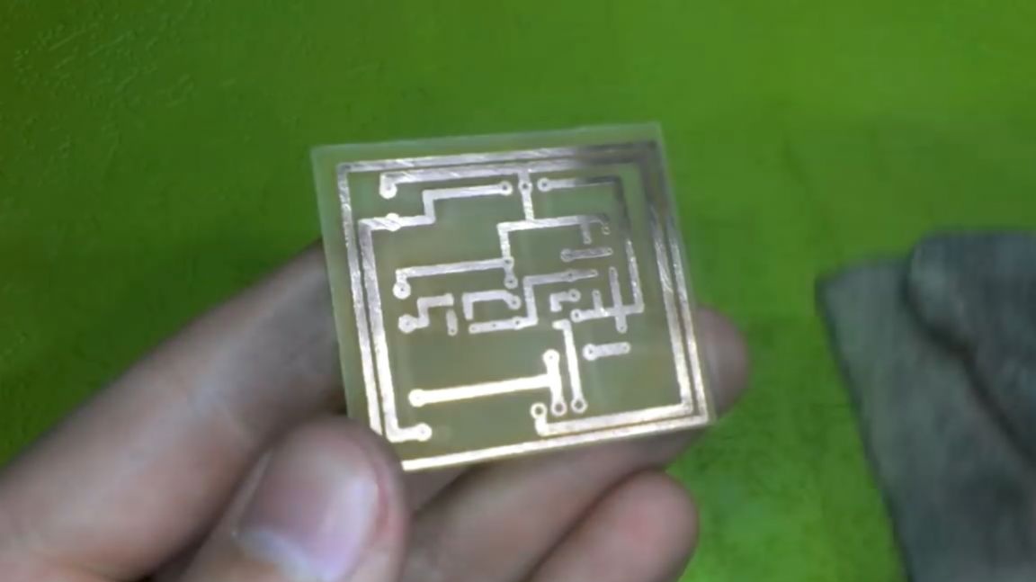
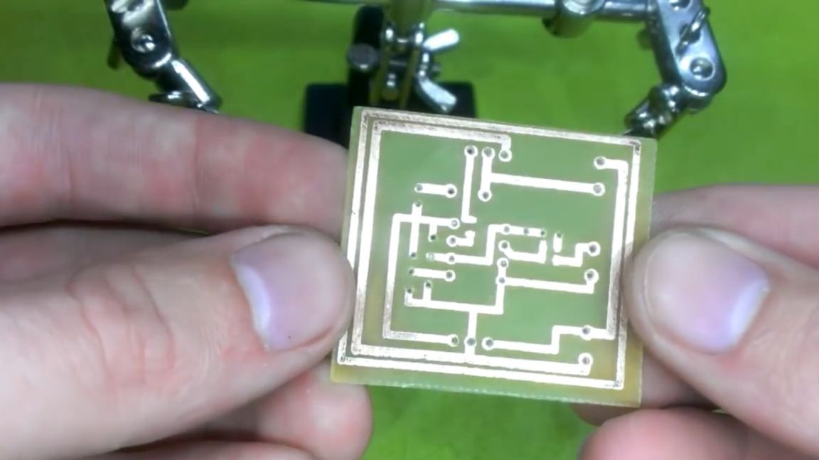
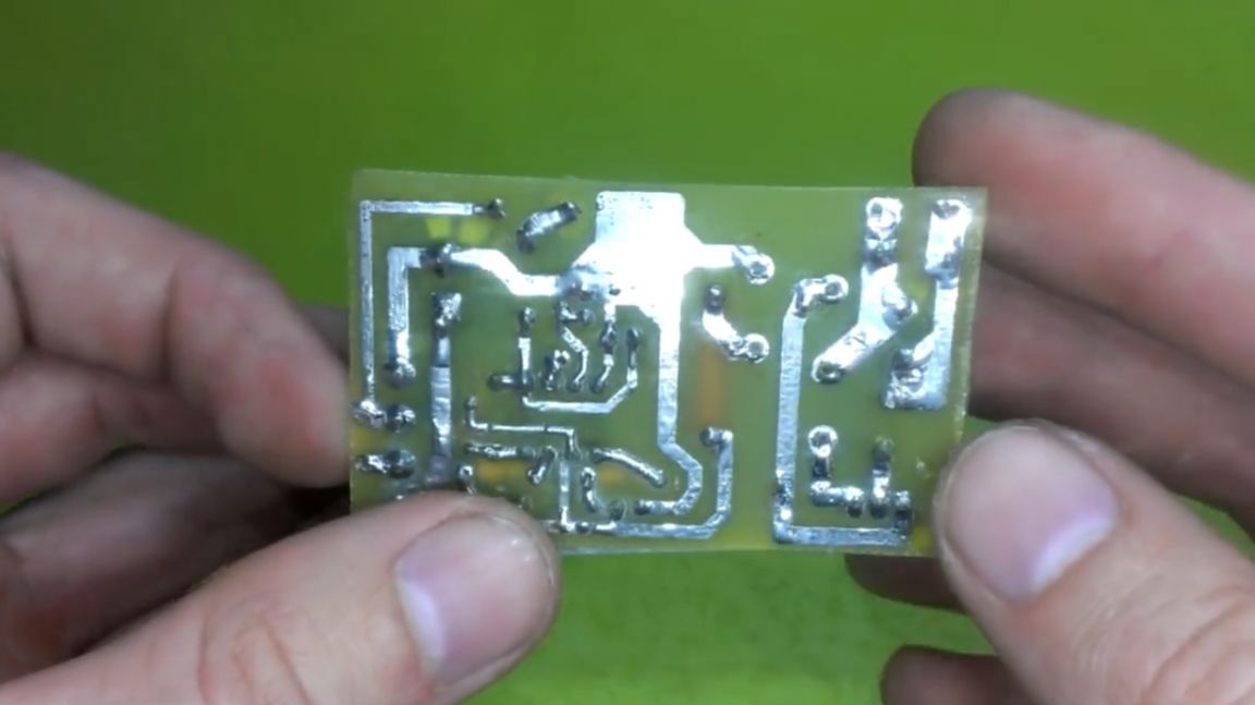
That's all, the manufacture of the board is finished, you can proceed to sealing parts.
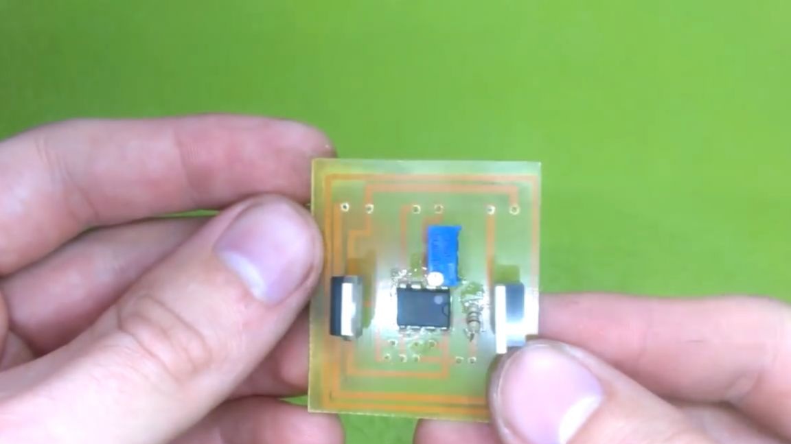
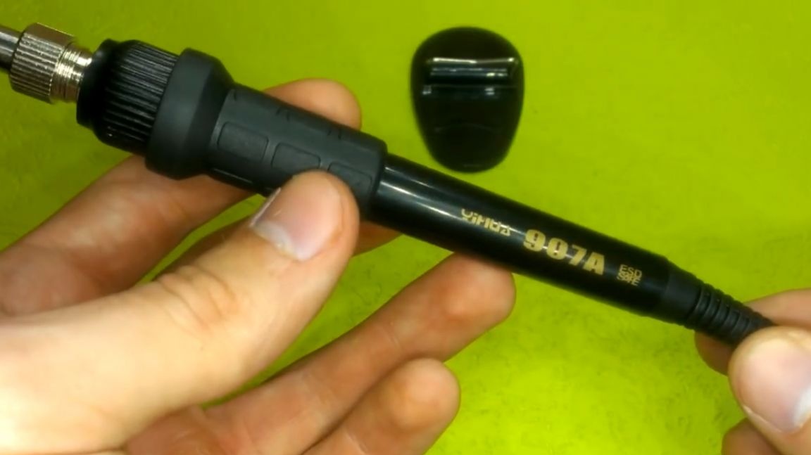
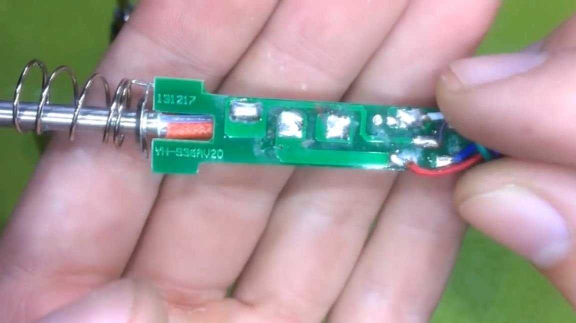
The regulator board was sealed up, washed from the remains of the flux, now you can connect a soldering iron to it. But how to do this if we do not know where is his solution? To solve this issue, you need to disassemble the soldering iron.
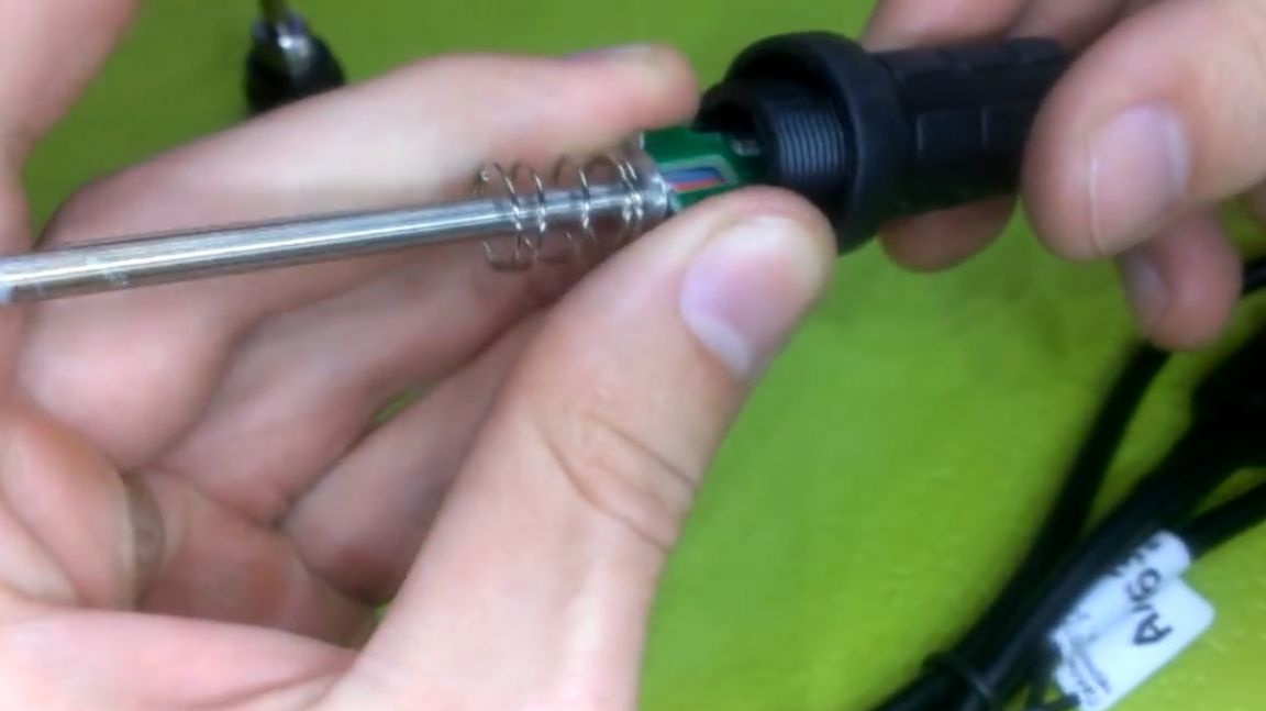
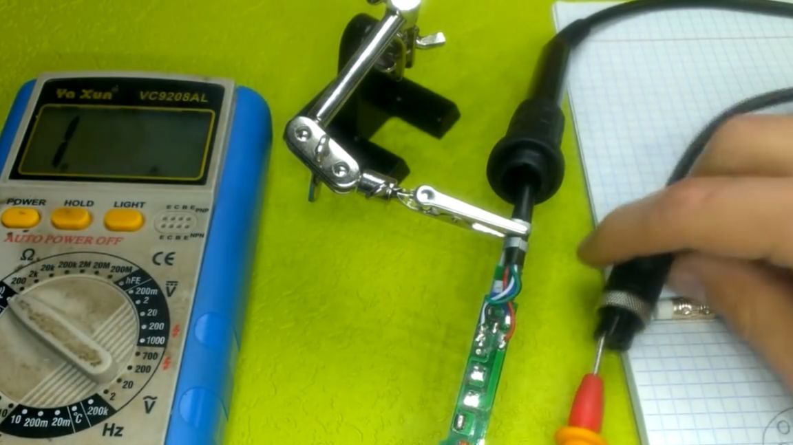
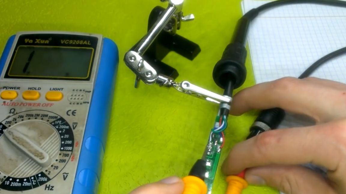
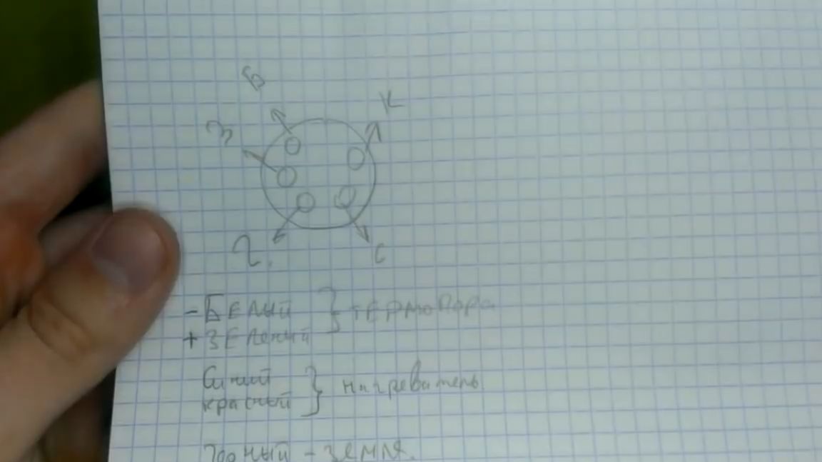
Next, we begin to look for which wire is going where, writing on paper in parallel, in order to avoid errors.
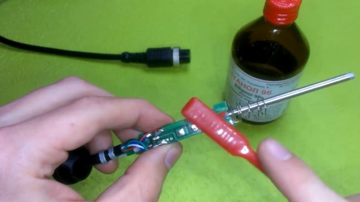
You can also notice that the assembly of the soldering iron was clearly carried out on a tyap. The flux is not washed and this needs to be fixed. This is fixed quite easily, nothing new, with alcohol and a toothbrush.
When they recognize the pinout, we take this plug:
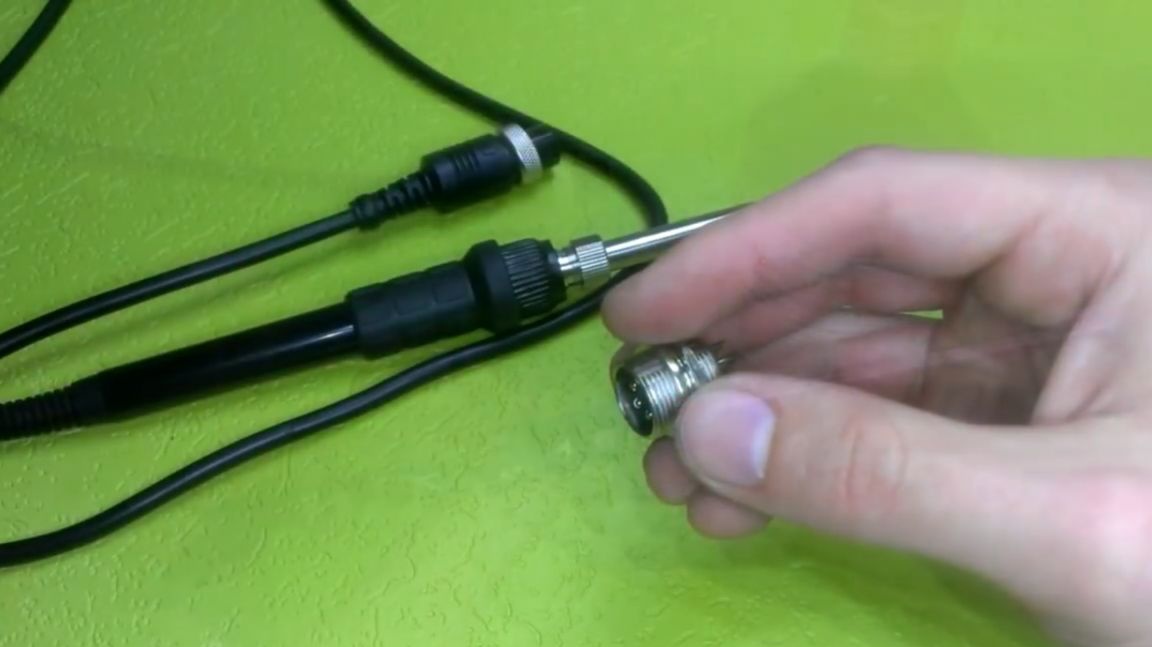
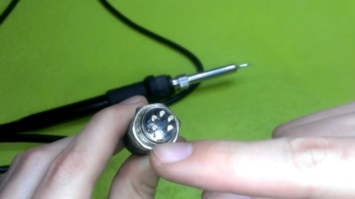
Next, we solder it to the board with wires, and also solder other elements: a voltmeter, regulator, everything is as in the diagram.
Regarding the soldering of a voltmeter. He has 3 conclusions: the first and second are power, and the third is measuring.
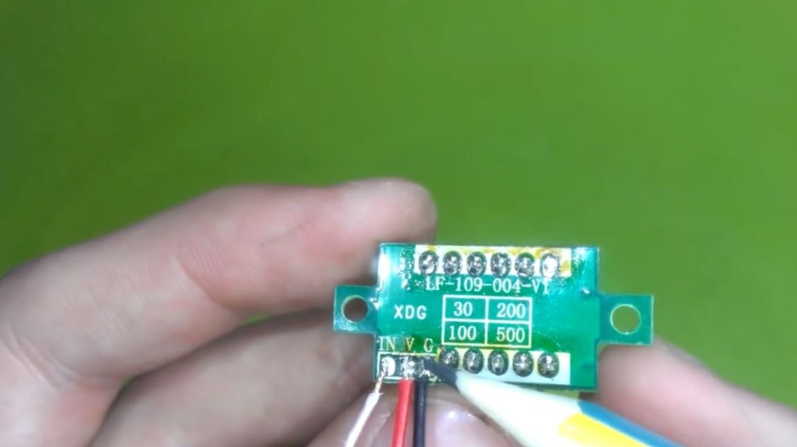
Often the test lead and power leads are soldered into one. We need to disconnect it to measure low voltage from the thermocouple.
Also at the voltmeter, you can paint over the point so that it does not knock us down. To do this, use a black marker.
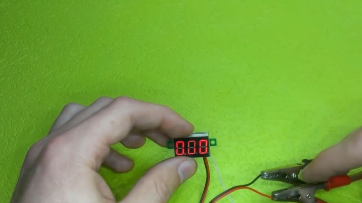
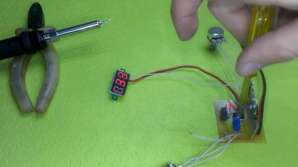
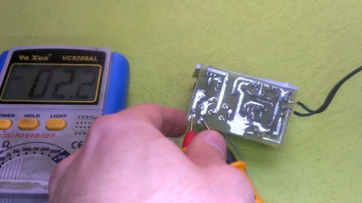
After that, you can turn on. The author takes food from the laboratory unit.
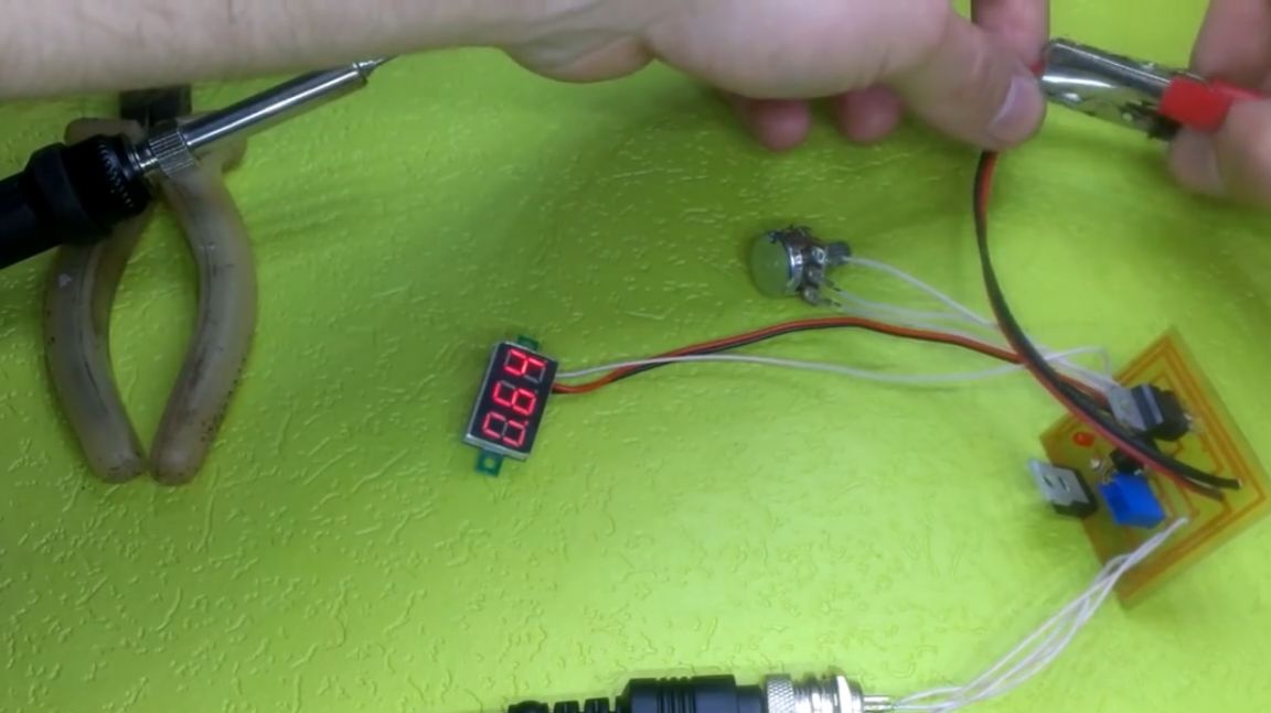
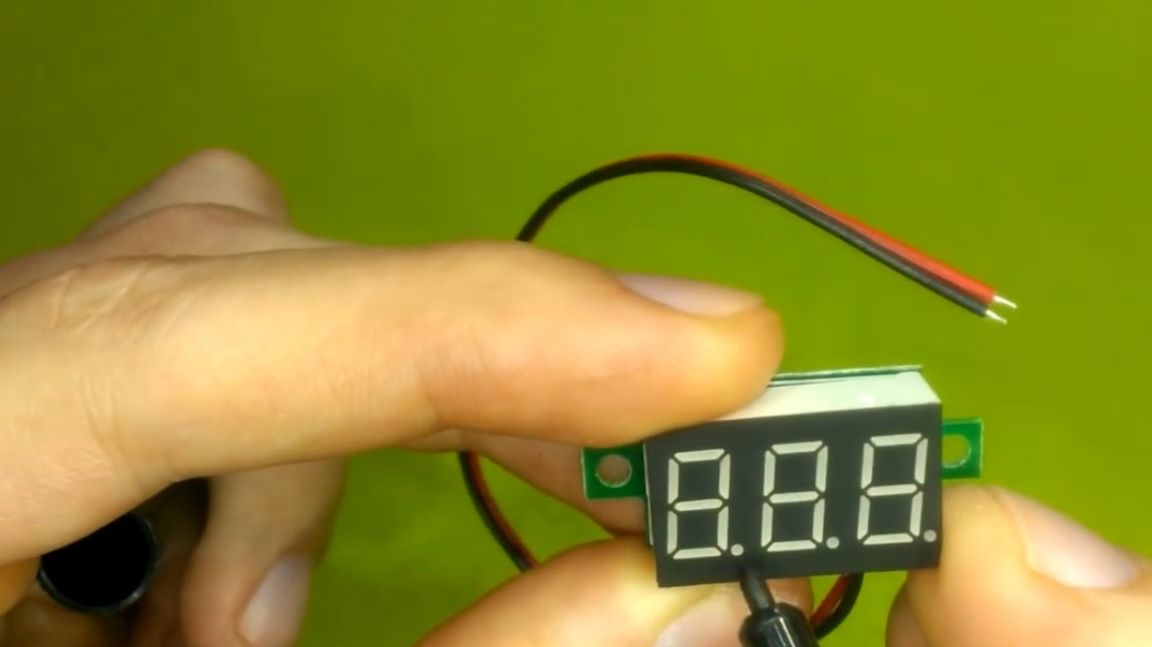
If the voltmeter shows 0 and the circuit does not work, you may have connected the thermocouple incorrectly. The circuit assembled without jambs starts working immediately. We check the heating.
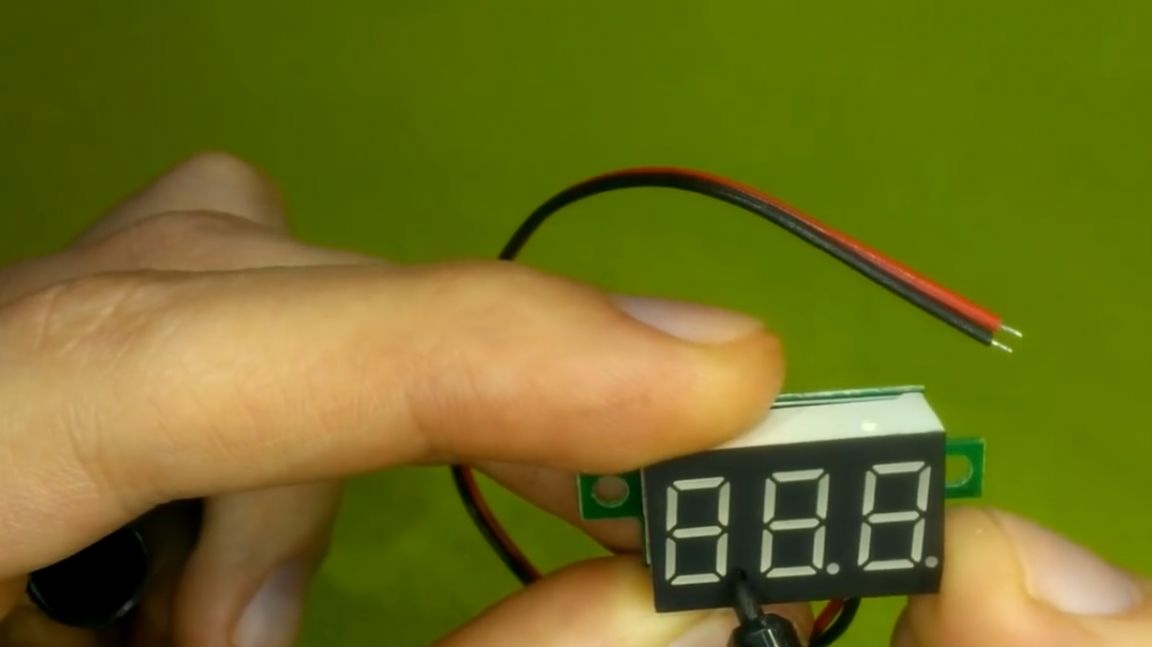
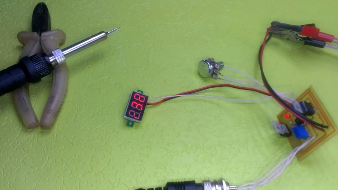
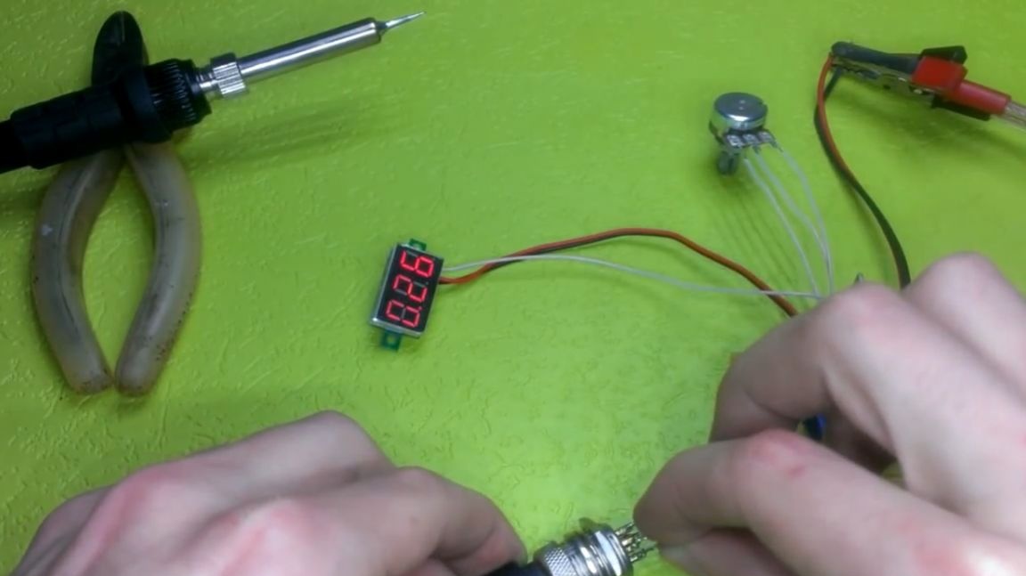
Everything is fine, now you can calibrate the temperature sensor. To calibrate the temperature sensor, turn off the heater and wait for the soldering iron to cool to room temperature.
Then, turning the potentiometer with a screwdriver, we set the previously known room temperature. Then for a while we connect the heater and let it cool. Calibration for accuracy is best done a couple of times.
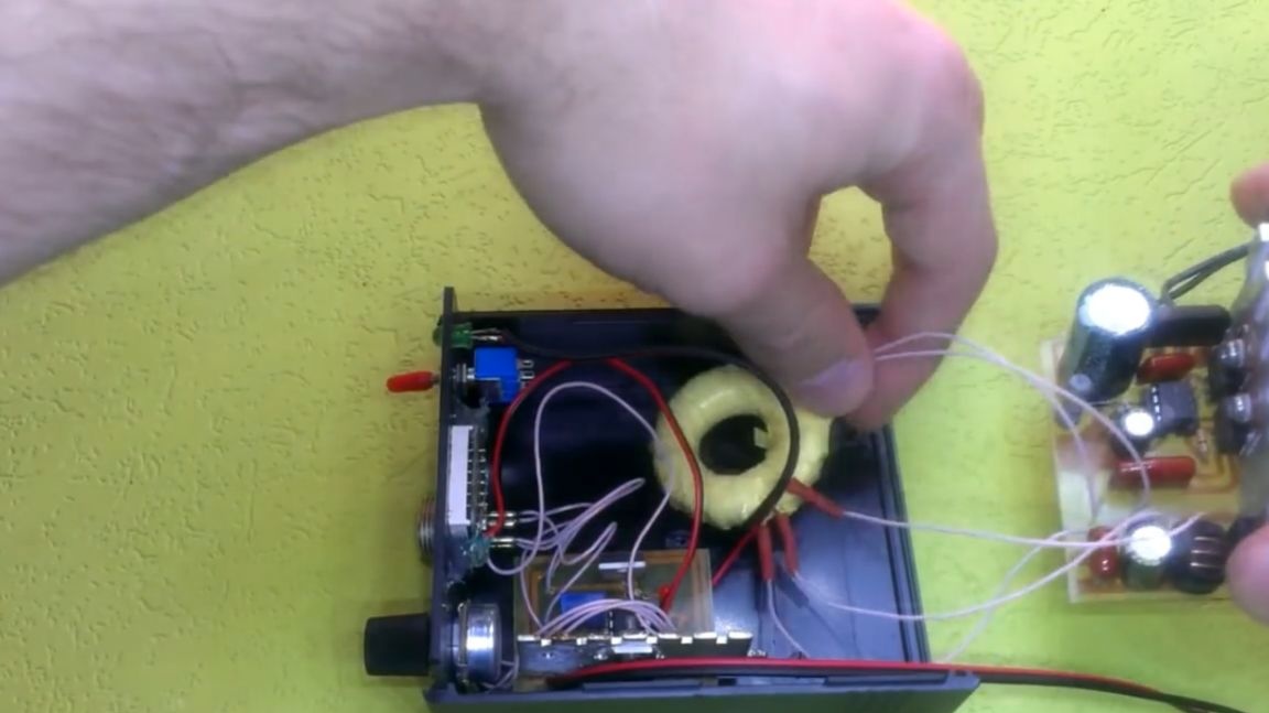
Now let's talk about the power supply. The finished board looks like this:
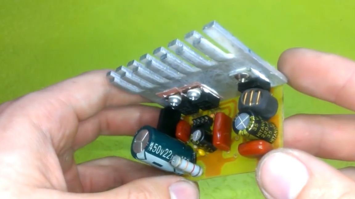
Also, it is necessary to wind a pulse transformer to it.
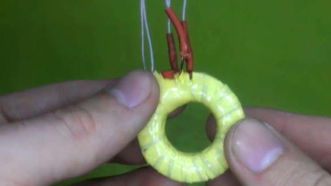
How to wind it, you can see in one of the previous videos of the author. Below you can find a screenshot of the calculation of the windings, who can come in handy.
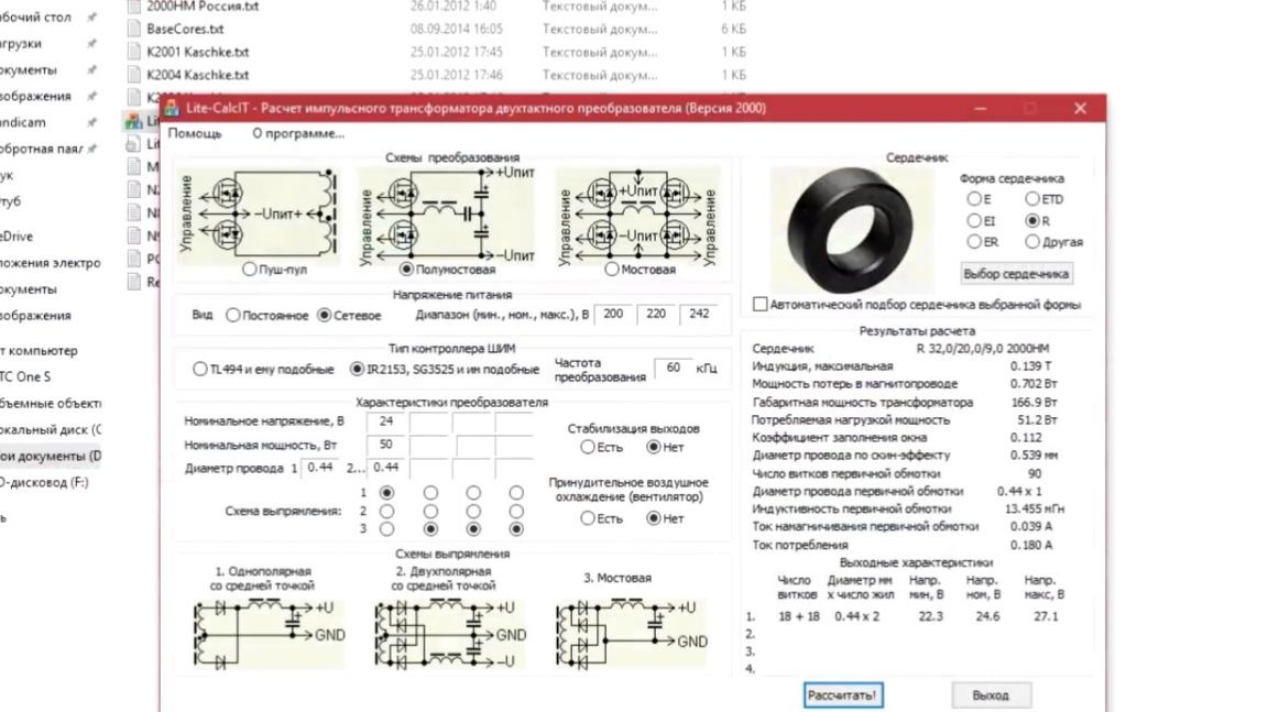
At the output of the block, we get 22-24 volts. We took the same thing from the laboratory block.
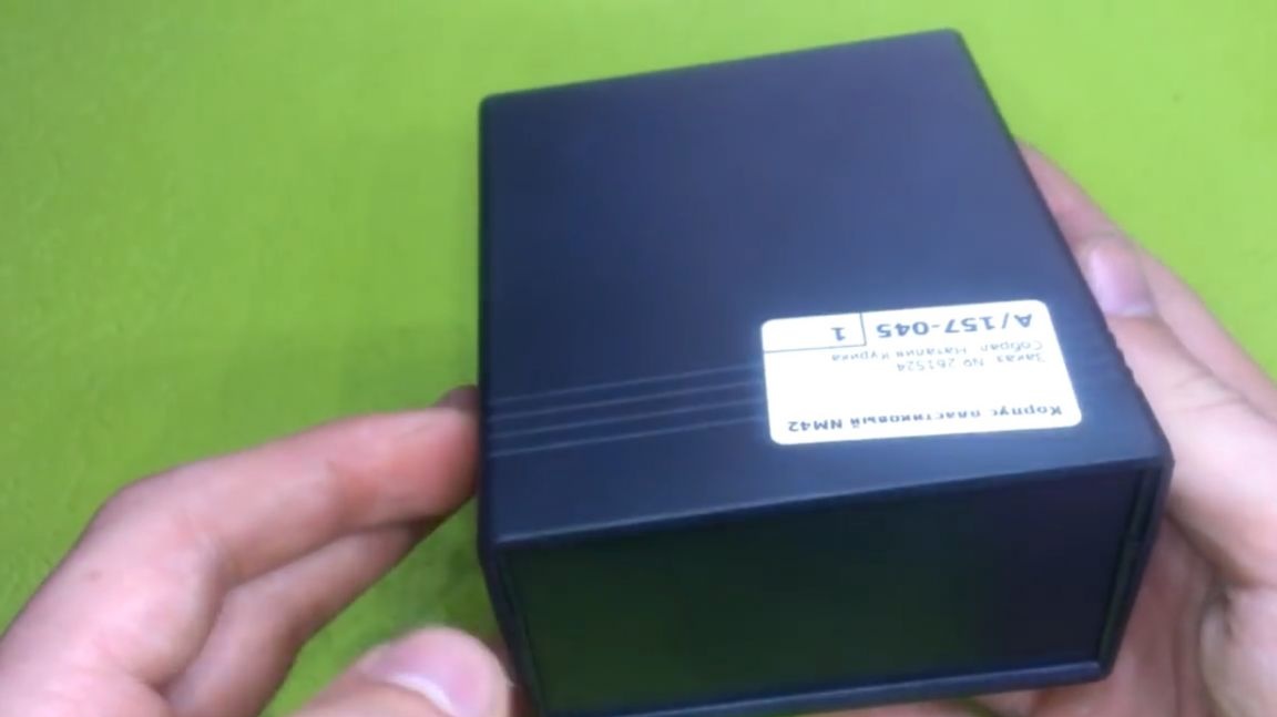
Housing for soldering station.
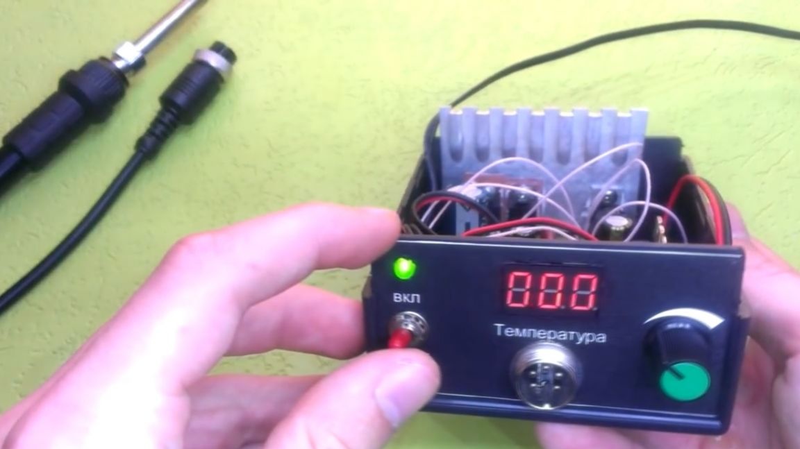
When the scarves are ready, you can begin to create a case. At the base there will be such a neat box.
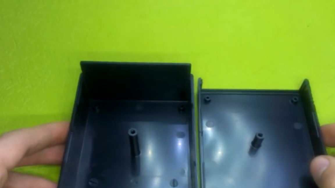
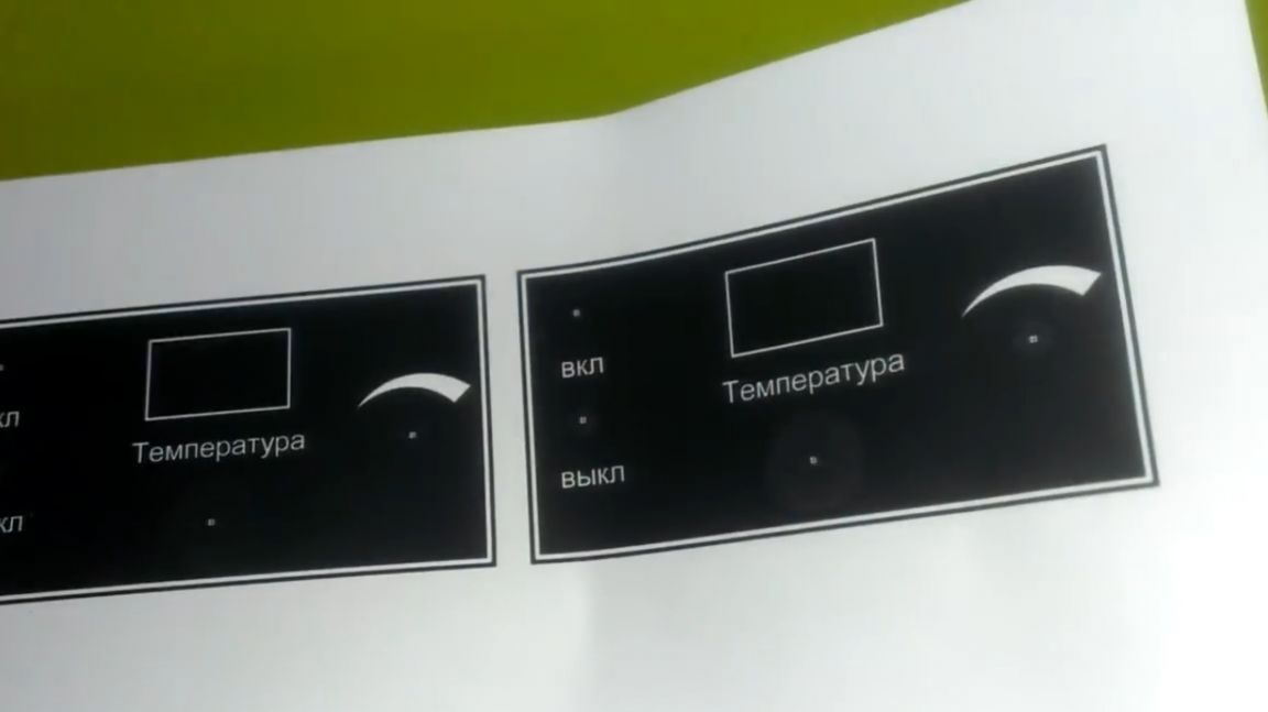
First of all, it is necessary to draw a front panel for it to give it a salable appearance, so to speak. In FrontDesigner, this can be done easily and simply.
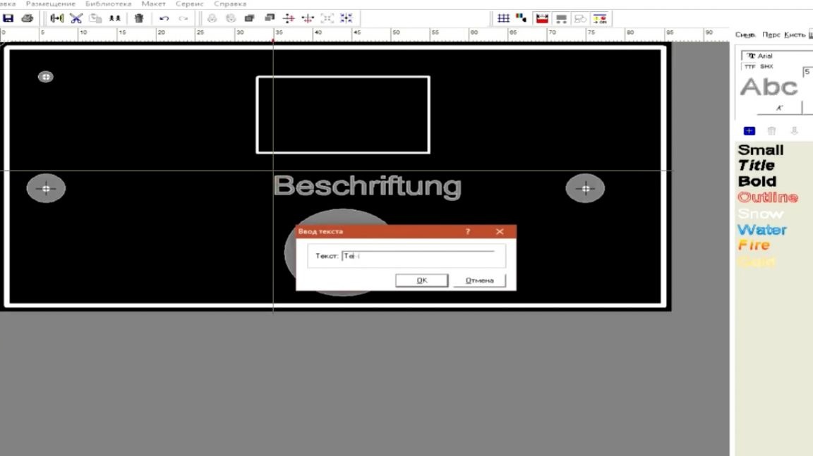
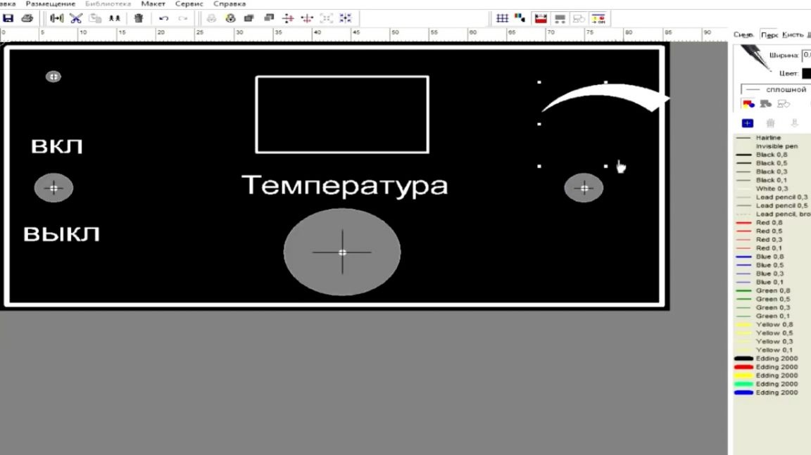
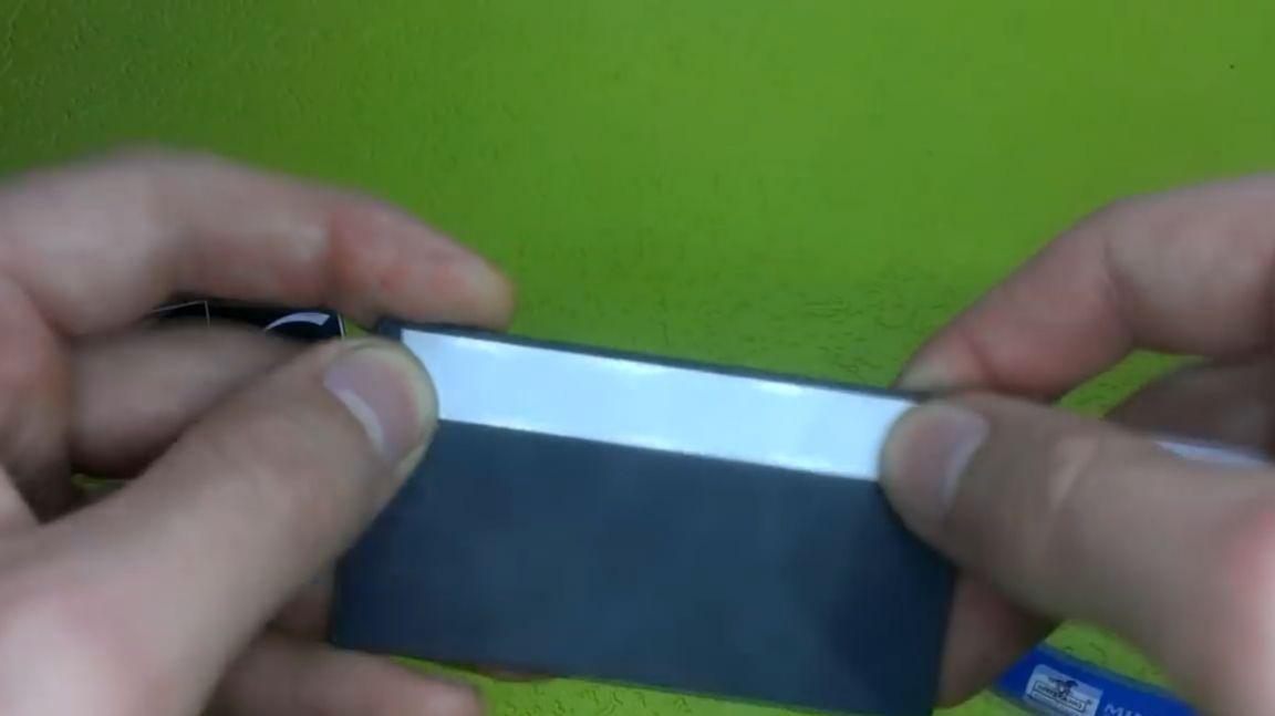
Next, you need to print the stencil and with the help of double-sided tape fix it on the end and go make holes for the parts.
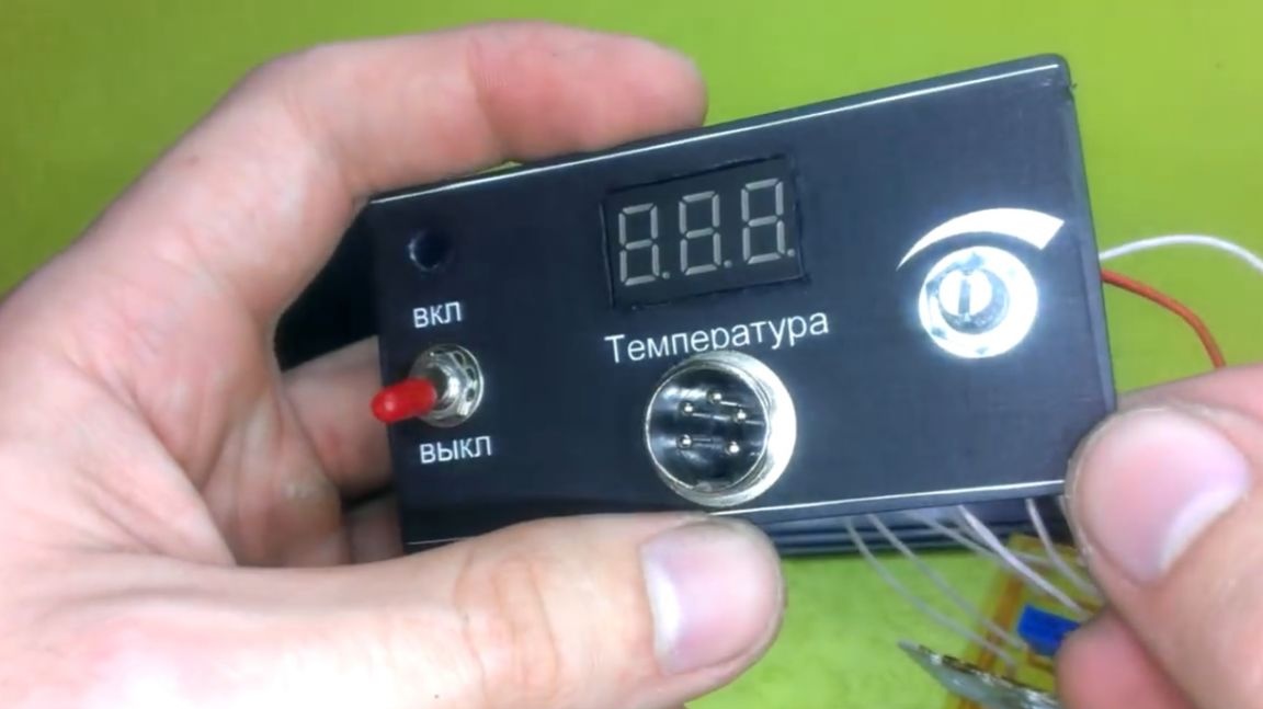
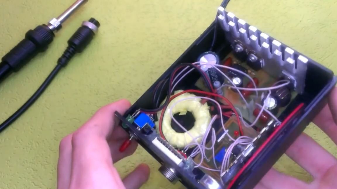
The case is ready, now it remains to place all the components inside the case. The author put them on hot glue, as the data electronic There is practically no heating of the components, so they will not go anywhere, and they will keep perfectly on the hot glue.
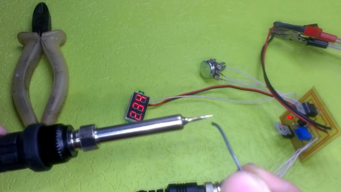
This completes the manufacture. You can start the tests.
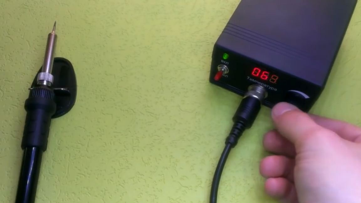
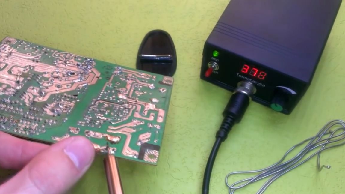
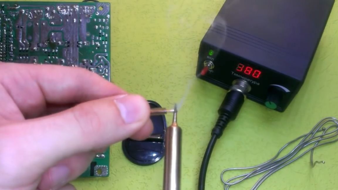
As you can see, the soldering iron does an excellent job of tinning large wires and soldering dimensional arrays. And in general, the station shows itself perfectly.
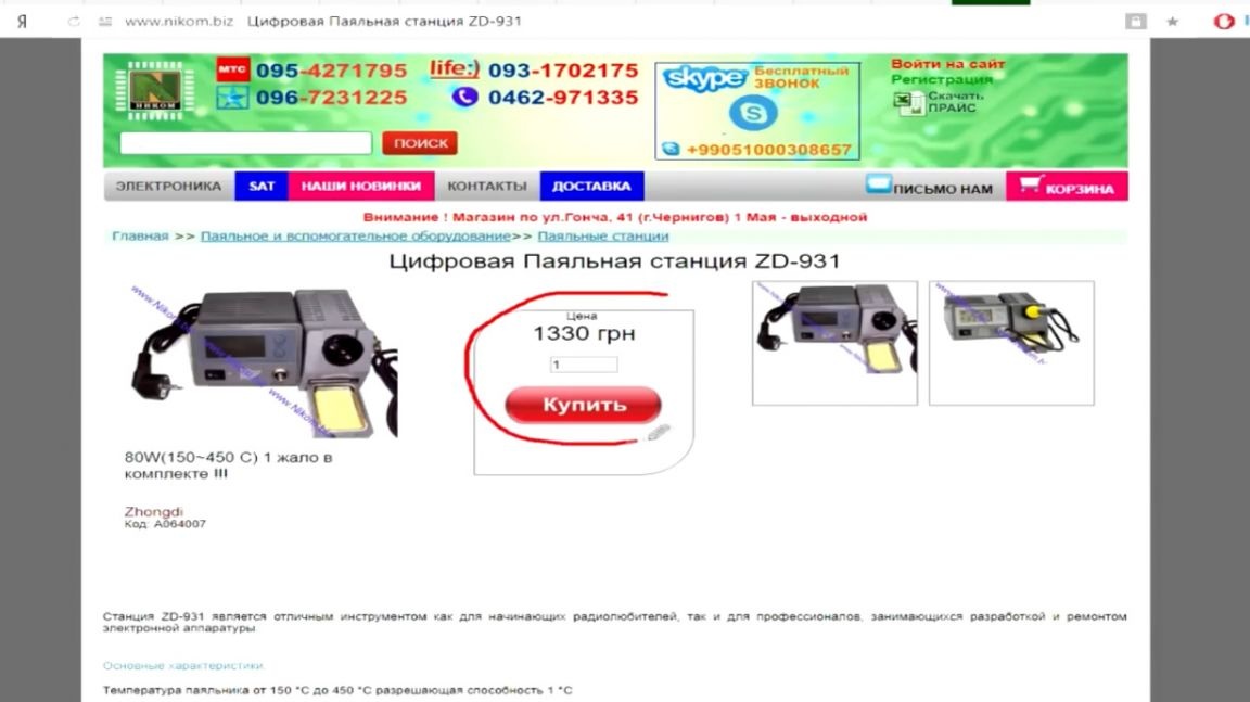
Why not just buy a station? Well, firstly, it’s cheaper to assemble it yourself. To the author, the manufacture of this soldering station cost 300 hryvnias. Secondly, in the event of a breakdown, you can easily repair such a homemade soldering station.
After operating this station, the author practically did not notice the difference between the HAKKO T12. The only thing missing is an encoder. But these are already plans for the future.
Thank you for attention. See you soon!
Video: