Good afternoon. People living in a private house often face the problem of the lack of high-quality Internet. ADSL is now in little use, and speed is poor. Especially problematic if the house is new and there is no telephone, then you will have to pull the wire for the sake of not very fast Internet. And if there is a telephone, it is not a fact that the line laid for a long time is suitable for the Internet. Fiber pull is expensive. Some add up with neighbors and then the costs may become acceptable. However, not everyone needs good internet. Remains mobile Internet. 4G technology allows you to reach 150 Mbps as much as possible, but for this speed you need high-quality signal reception. Not always the built-in antenna (more precisely two) of the modem is enough for this. So, today we will manufacture the Harchenko antenna for the 4G Yota modem. YOTA 4G LTE WLTUBQ-108 modems are currently on sale.
We have to:
- YOTA 4G LTE WLTUBQ-108
- Copper wire with a section of 2.5 mm
- Iron sheet
- 75 ohm coaxial wire, thin
- Pigtail double with MS156 on SMA Female
- SMA Male Connector
- drill
- 3 mm drill
- Plastic tube or any dielectric
- soldering iron
- Solder, rosin
- Hot glue
- Homutiki
- USB extension cable
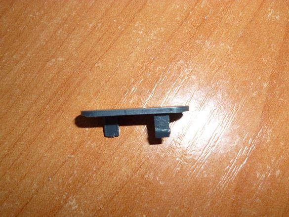
Step 1 Preparing the modem.
Before starting the manufacture of the antenna, it is worth connecting the modem to a computer. Having entered the modem settings at the address 10.0.0.1, write down the SINR / RSRP values. This should be done to compare the change in signal level, after connecting the antenna. The modem understands quite easily. You need to pry off and remove the top cover with something sharp, such as an awl or knife. This must be done very carefully, as there is a built-in antenna under the cover. The main thing is not to damage her. Remove the cover:
Next, hold the modem by the USB connector with one hand, and remove the modem case with the second one:
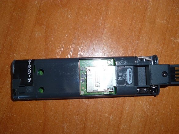
And on the back, it looks like this:
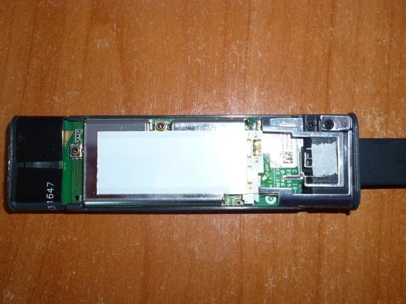
Our modem supports MIMO technology. MIMO (Multiple Input Multiple Output, multiple inputs, multiple outputs) - spatial signal coding technology, thanks to which you can increase the channel bandwidth. When using this technology, two or more antennas and the same number of antennas for reception are used for data transmission. In our case, we have two antennas. Each antenna has its own slot:
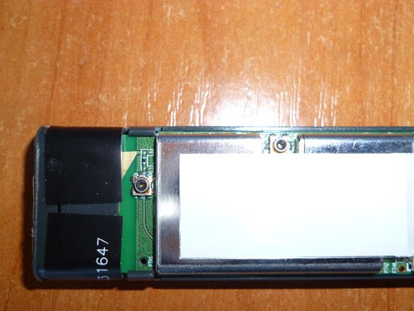
One slot is located at the top of the modem, the second on the side on the right. It is not good to leave the modem open, therefore, applying the case to the modem, we measure the places of the holes for the slots, and drill with a 3 mm diameter drill:
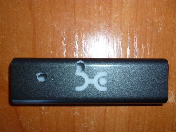
It is difficult to die out for sure. After drilling the holes we put the case on the modem and see if the holes coincide with the sockets. If necessary, increase the holes with a knife in the desired direction. After making sure that the holes coincide with the sockets, we put on the case and close the top cover.
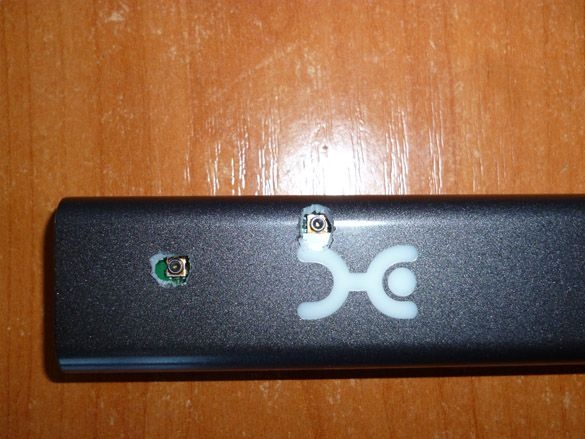
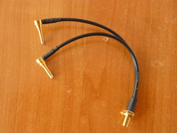
We will connect the antenna to specially prepared sockets. For this we need an adapter. On the one hand, there will be two MS156 connectors (we connect one antenna to two sockets), on the other hand, a high-frequency SMA Female connector. It can be ordered on aliexpress or bought at the radio parts store:
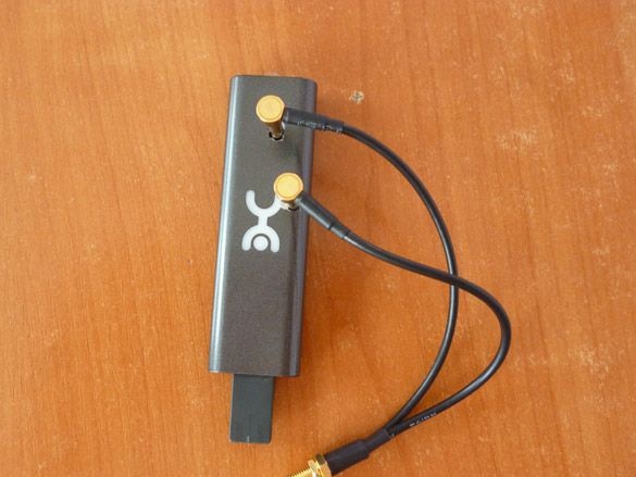
Connect the pigtail to the modem:
On this we postpone, for a while, the modem aside.
Step 2 Calculation of the antenna.
Antenna options are many. In my opinion, the most efficient and easiest to manufacture is the Antenna Kharchenko. It is named after the engineer who developed and described the design of this antenna - KP Harchenko. The antenna vibrator will be made of copper wire with a cross section of 2.5 mm. You can use a wire with a cross section of 2 mm. The wire is easy to buy in an electrician. Before making the antenna, the insulation of the wire should be removed. The vibrator consists of two squares connected at one of their vertices and with the sides disconnected. The antenna wire is soldered at the junction points of the squares. The input impedance of the antenna is close to 50 ohms. I chose a 75-Ohm cable, although it also fits well with a 50-Ohm coaxial cable. The length of the sides of the squares is λ / 4, where λ is the wavelength. In our case, it is 115 mm. We make a vibrator according to the following scheme:
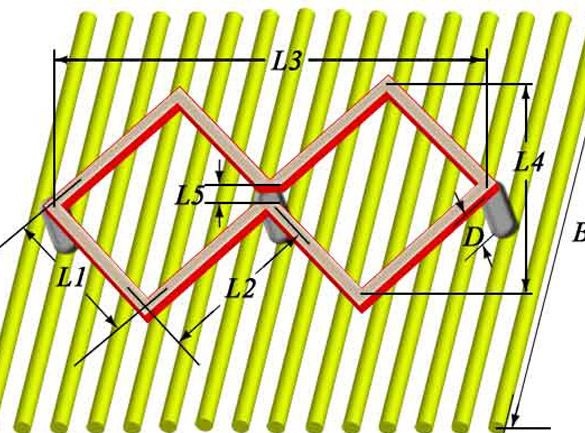
Where:
Center frequency f: 2600 MHz
Antenna impedance ρ: 50 Ohm
Wavelength λ: 115 mm
Size L1 (outside of the square): 28.9 mm
Size L2 (inside of the square): 27.6 mm
Size L3 (total frame length): 81 mm
Size L4 (Bezel Width): 40.5 mm
Size L5 (gap at the connection point): 1.7 mm
Distance Vibrator Reflector D: 13.2 mm
Size B (reflector width): 115 mm
Size H (reflector length): 115 mm
Vibrator wire diameter: 2.5 mm
Total wire length (with margin for turns): 237.9 mm
Step 3 Assemble the antenna.
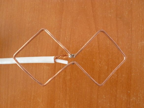
Solder the wire to the vibrator. The result should be like this:
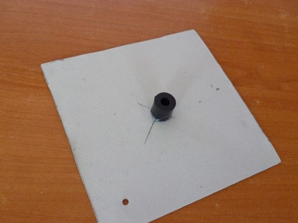
The reflector can be made from almost any metal sheet. It is also possible to manufacture a mesh reflector. I chose and recommend that you make it from metal from the old computer system unit. The thickness is sufficient, and the coating helps a lot. Cut a square with a side of 115 mm. You can cut more, I indicate the minimum necessary side of the square. In the center we make a hole of 6 mm. In the corner of the reflector, we also make a 6 mm hole for attaching the antenna. Then we take a small plastic tube or a tube from any dielectric. We cut off 13 mm from it and, using hot-melt adhesive, fix the resulting part in the center of the reflector, so that the holes of the reflector and the tube coincide:
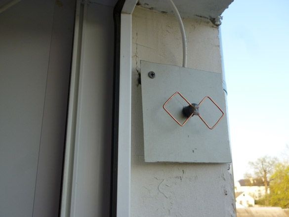
We pass the wire with the soldered vibrator into the central hole of the reflector. Using hot glue, fix the vibrator. Before installation, think carefully about the installation location. The antenna must be positioned so that the vibrator is horizontal. Also, it must be turned by a vibrator towards the receiving tower. It is better to place the antenna indoors. If you plan to use it outside, you should take care of waterproofing the antenna. I mounted the antenna on the slope of a window on the street. In order to get as little rain and snow as possible, I fixed it in the upper part. Thus, it is, as it were, under the visor:
Do not forget to drill a hole in the window frame and thread a wire into it.
Step 4 Connect the antenna to the modem.
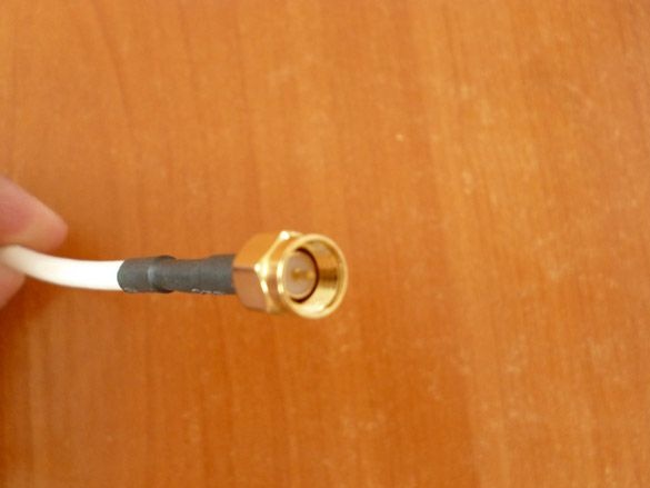
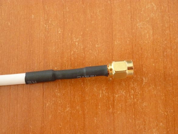
At the end of the wire, install the SMA Male connector. The middle contact must be soldered, the outer braid is fixed with a metal tube, insulated with heat shrink or electrical tape:
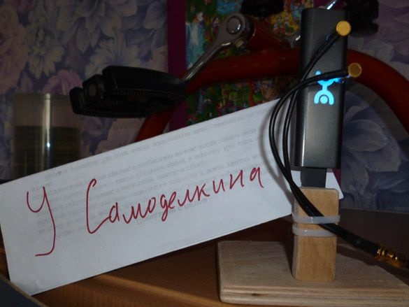
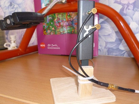
The pigtail is not very stable in the modem sockets.At the slightest movement, the pigtail connectors fall out of the sockets. Therefore, it is worth making a small pedestal for the modem. Such a pedestal is convenient without an antenna. You can simply put it on a windowsill or cabinet, and the signal will already be better than if the modem was sticking out somewhere behind the system unit. From the plywood, cut a square with a side of 10 cm. And a small rectangle of 2 x 3 cm. We twist them as shown in the photo. Using a cable tie, we fasten one end of the USB extension cable to the rectangle. As for the extension cord, it is worth choosing an extension cord with a thicker wire and a length of no more than 70 cm. In longer ones, there will be big losses, and the modem may not start up due to insufficient power. Also, large losses will be in too thin wires. We put the modem in the extension cord connector, insert the pigtail and fix the pigtail wire with another clamp. Thus, we exclude accidental disconnection of the antenna:
Having connected the antenna to the modem, and the modem to the computer, we go into the modem settings at 10.0.0.1. Based on the SINR / RSRP indicators, we find the best place for the antenna.
SINR - An indicator characterizing the ratio of noise (interference) and signal level. For stable data transmission, the value of the indicator should be greater than 2.
RSRP - Indicator characterizing the quality of the signal from the base station. The higher this value, the better the connection. A sufficient indicator value is considered to be from -110 and above.
For comparison, I will give my indicators. Without an antenna, the values are as follows:
SINR 7, RSRP -112.
After connecting this antenna, the indicators of steel:
SINR 15, RSRP -92.