
Hello to all lovers homemade. In this article I will tell you how to make a digital oscilloscope do it yourself, in the assembly of which the kit kit will help us, which you can order by the link at the end of the description. This kit kit will be an indispensable tool for those who know how to hold a soldering iron in their hands and understand something in radio electronics, also such a kit will help save you money, since a serious oscilloscope costs a lot.
Before moving on to reading the article, I suggest watching a video where the entire assembly process of this kit kit is clearly shown, as well as its testing.
In order to make a digital oscilloscope with your own hands, you will need:
* Kit
* Soldering iron, solder, flux
* Side cutters
* Device for soldering "third hand"
* Multimeter
* Flat-head screwdriver
* Test phone with 3.5 mm plug
Step one.
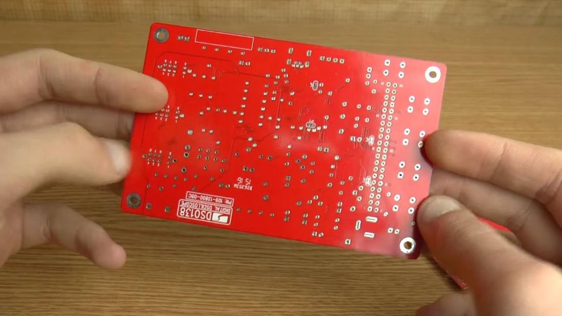
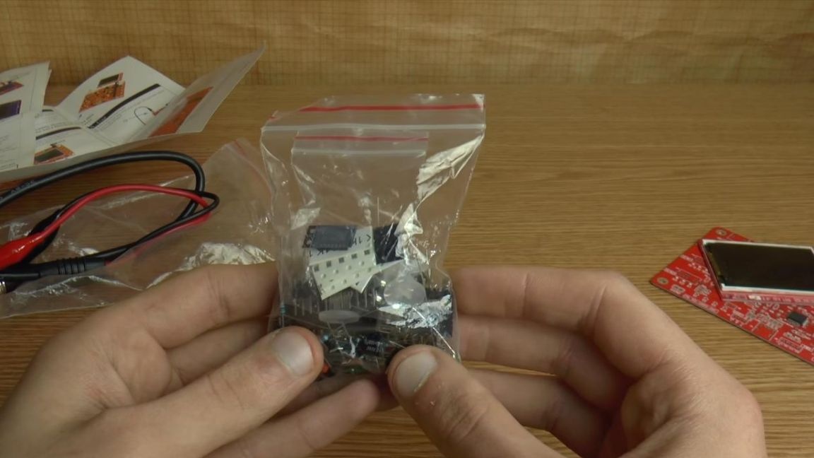
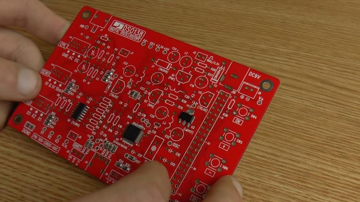
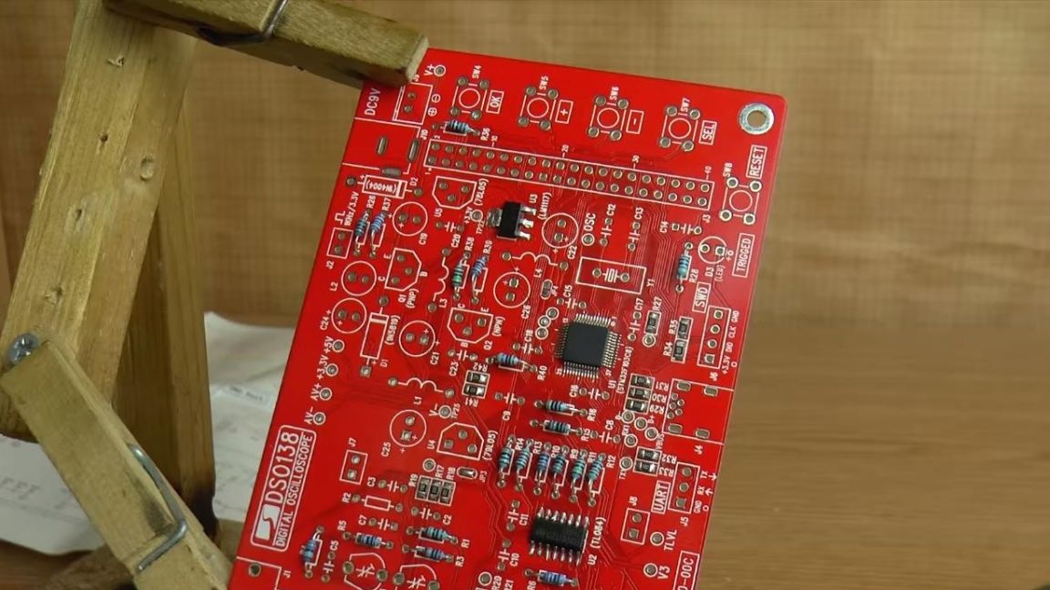
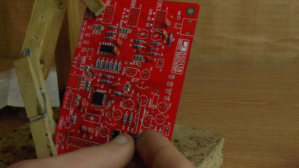
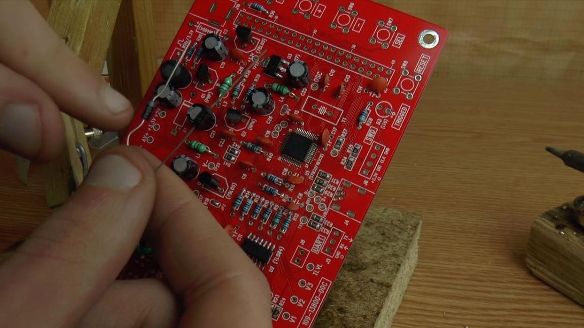
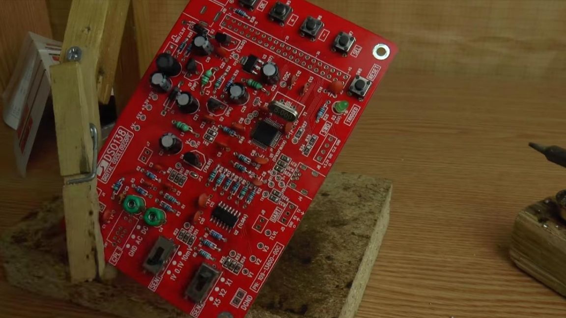
To begin, consider the kit kit kit and figure out what's where. Here we have a printed double-sided board, which is made on red textolite, and quite high quality and with a microprocessor already wired on it with firmware for the oscilloscope to work correctly.
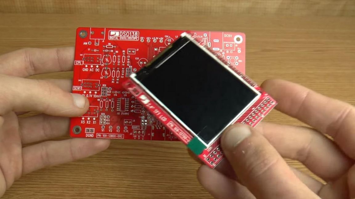
Also included is a color display, which is also installed on a printed circuit board, it will be mounted on top of the main board using special connectors, which are also in the kit.
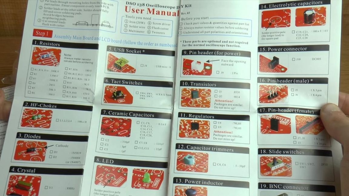
In order not to get confused during assembly, there is an English manual, the ratings of all components, their position are shown here, for greater convenience there are places to tick the part that you have already set, which is very convenient, the setting is also described at the end ready-made kit.
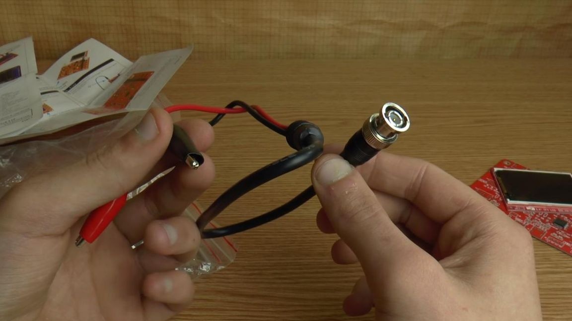
The set has fairly high-quality probes with a connector.
Since there are SMD components in the kit, a soldering iron in this case will be needed with a thin tip, at best a soldering hair dryer. Now we pass directly to the assembly.
Step Two
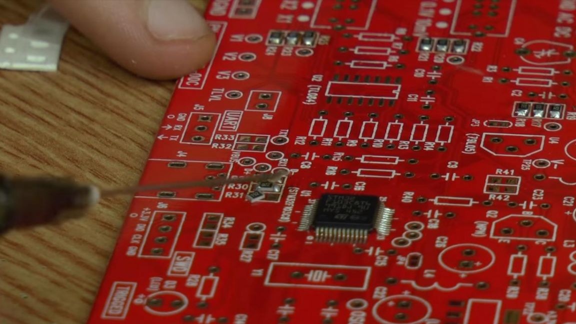
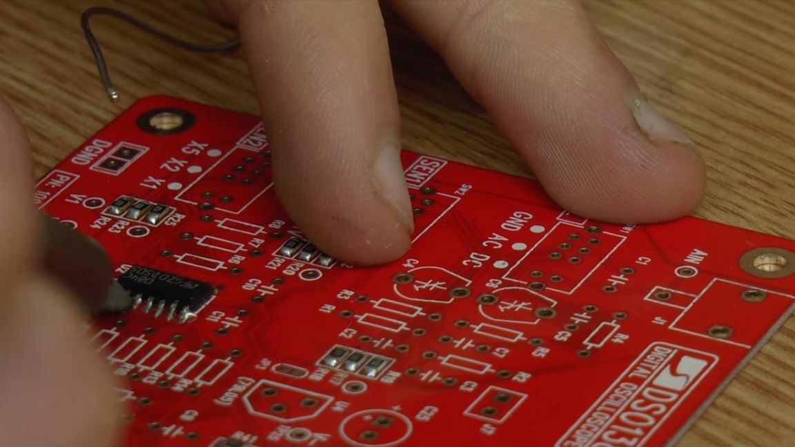
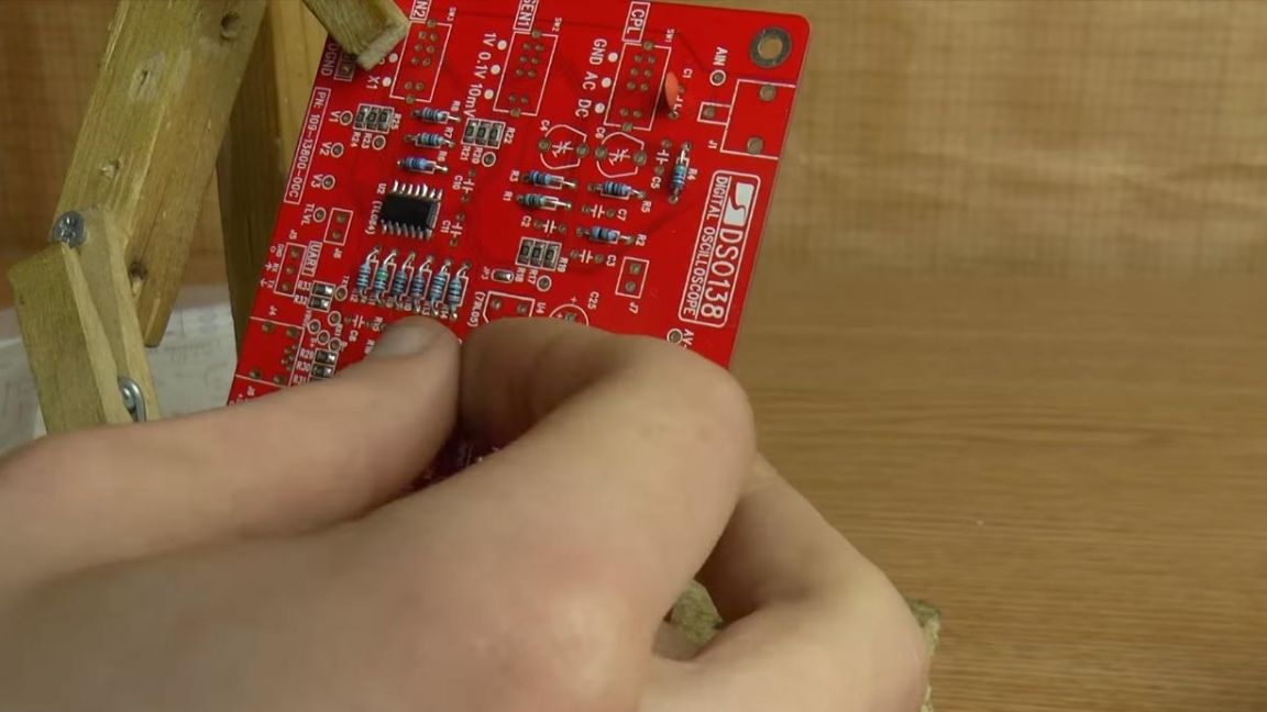
The first thing we will install on the board is the SMD components, in this case these are resistors, their resistance is written on the package.
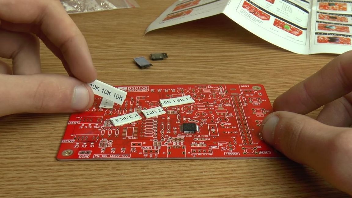
Also, the values are indicated on their case by a numerical code, which is a three-digit number, the first two digits of which indicate a numerical value, and the third digit by a factor, for example, an SMD resistor marked 103 has a resistance of 10 * 1000 = 10 kOhm. According to the marking from the instructions, we arrange the components in their places and immediately apply the flux to the soldering place, and then solder it with a soldering iron with a thin sting.
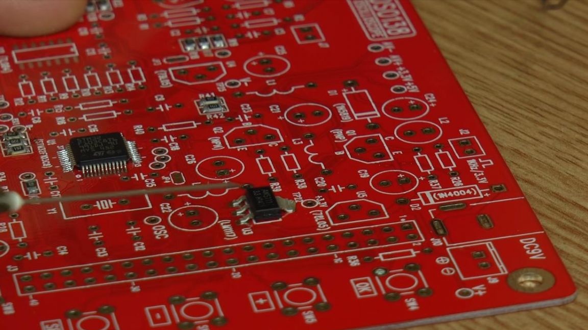
We install an SMD transistor with three pins on the board, its position cannot be mixed up.
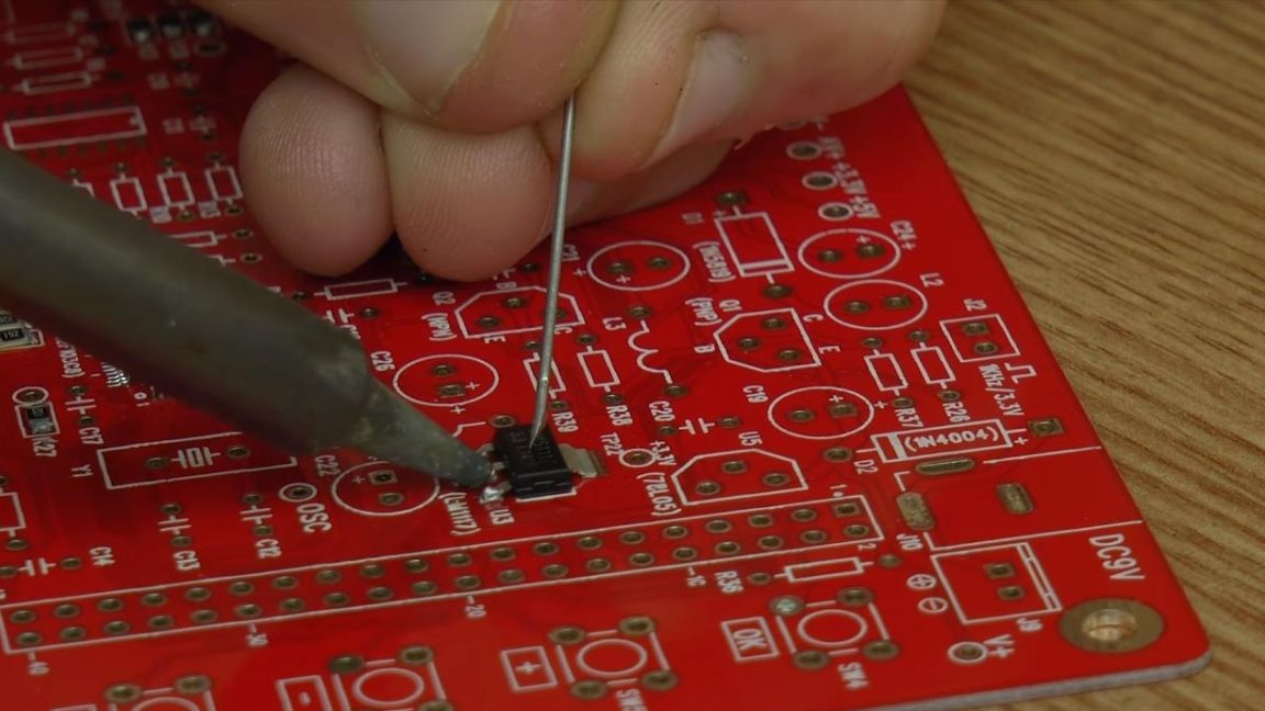
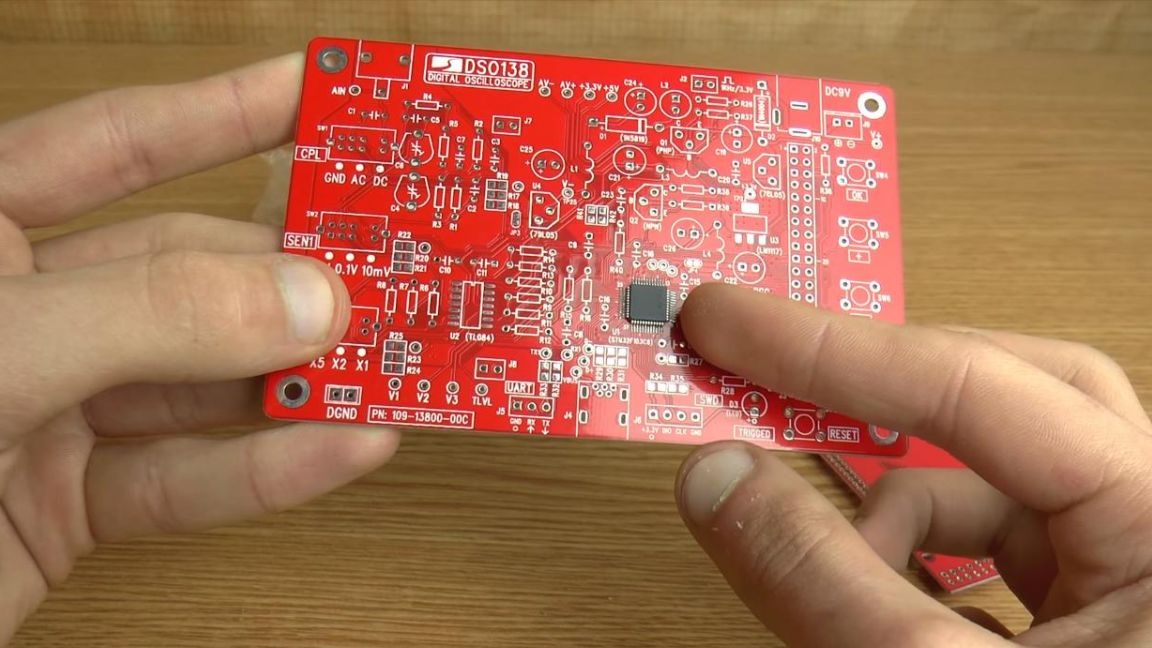
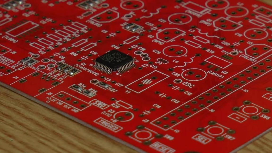
After we solder the microcircuit, combining the key on the case in the form of a point with the key on the board.
That's all with the SMD parts, now let's move on to the DIP components.
Step Three
Using the same principle, we install the remaining DIP resistors, that is, those that are inserted into the holes on the board.
In this case, their resistance can be determined in several ways, using a multimeter, color coding, which is shown on the resistor case, as well as in the online calculator, where it is enough to enter the color of the strips from the case.
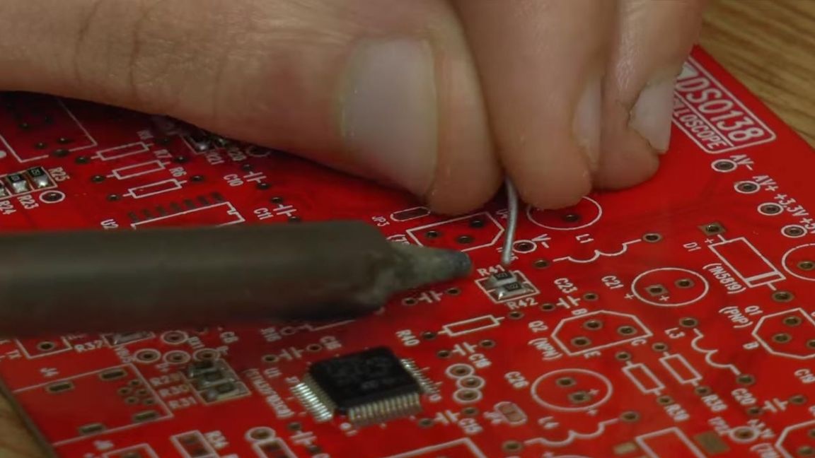
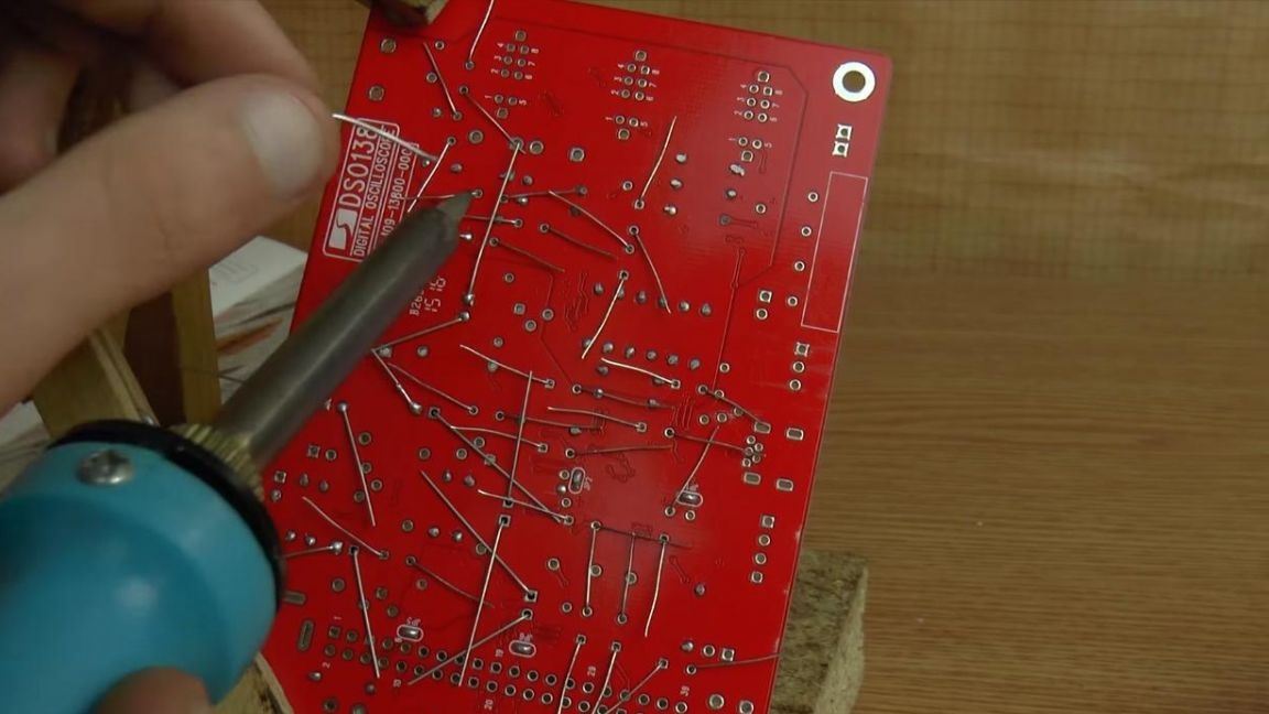
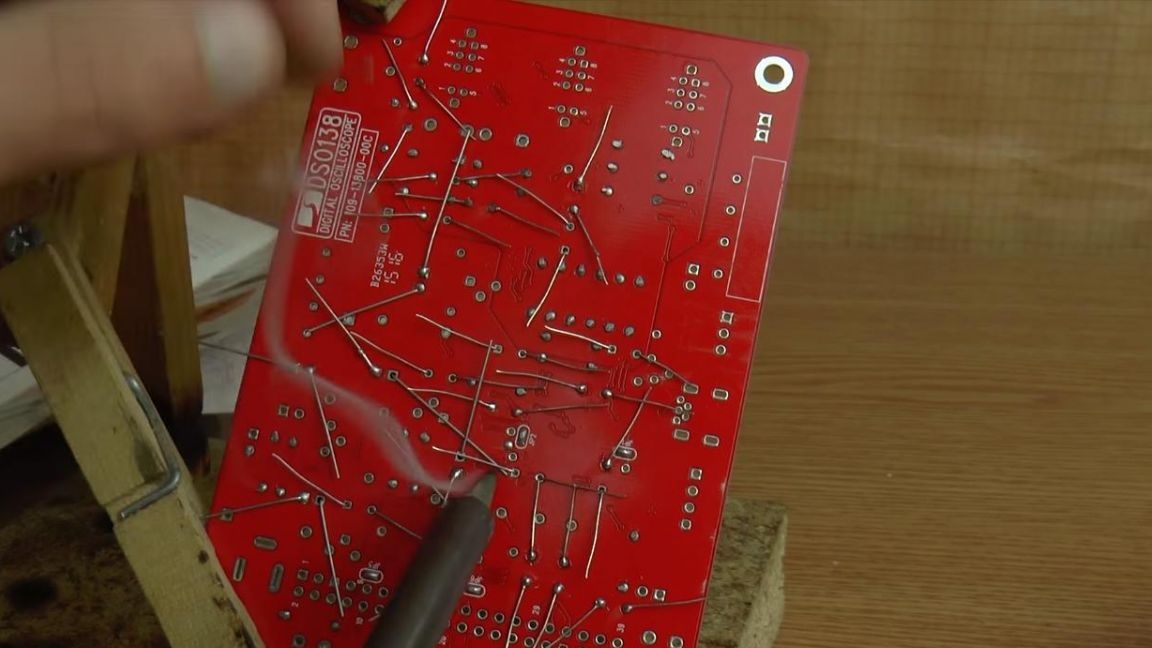
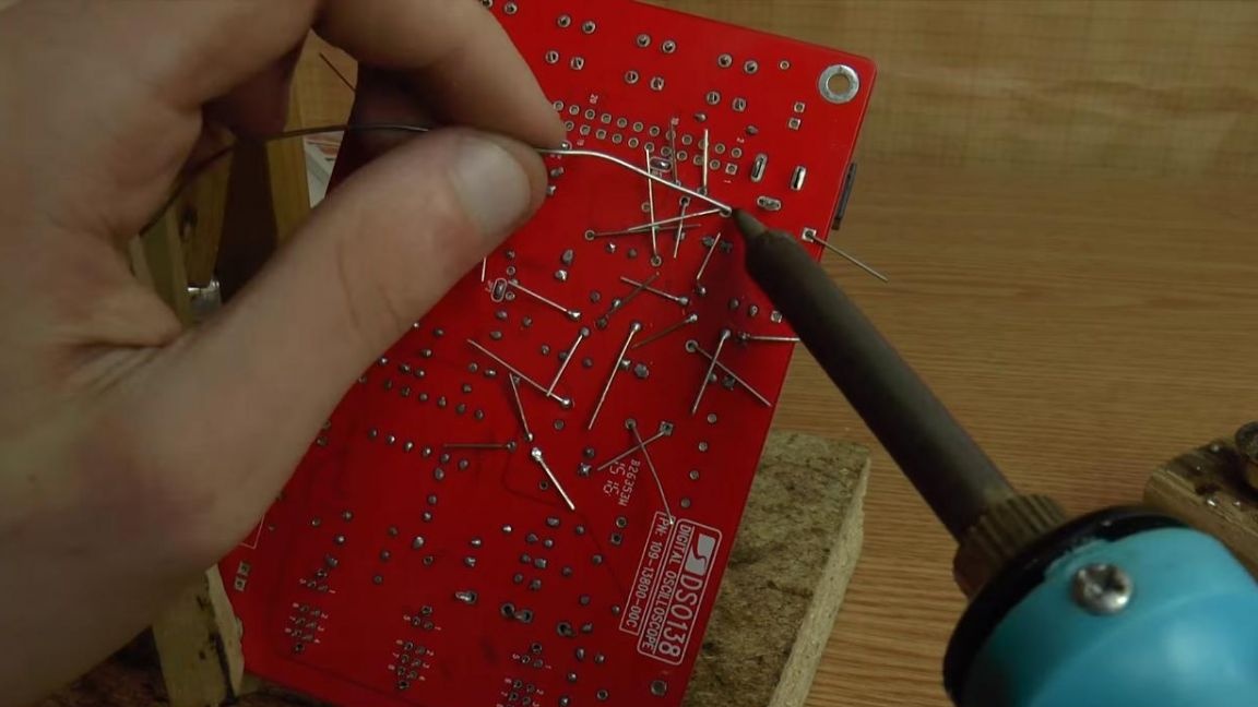
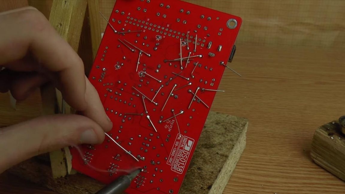
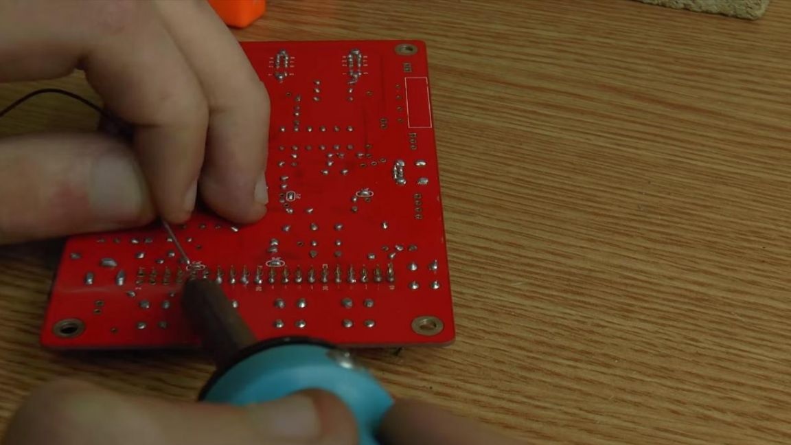
After installing it on the board, we solder the resistors, fixing the board in the third-hand soldering device.
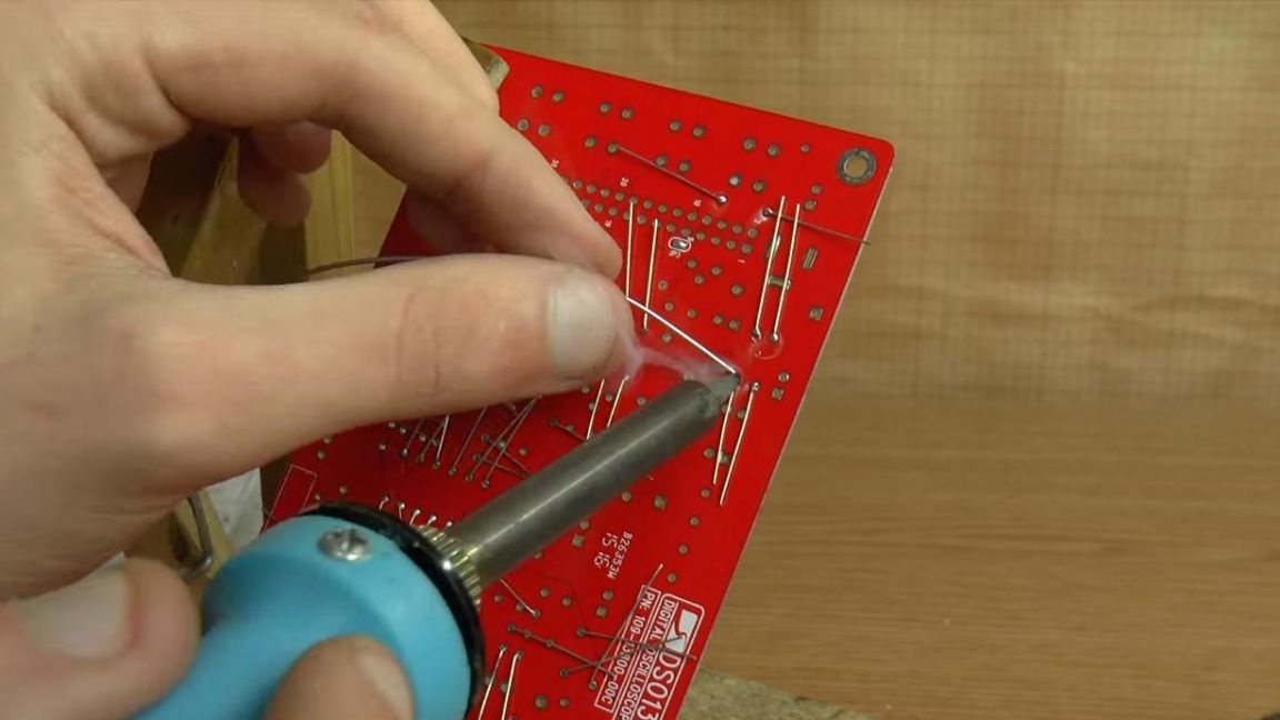
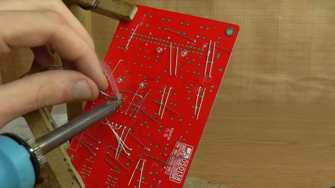
Then you need to remove the remnants of the findings using side cutters. When biting the legs of parts, be careful, as together with the leg you can remove the track from the board.
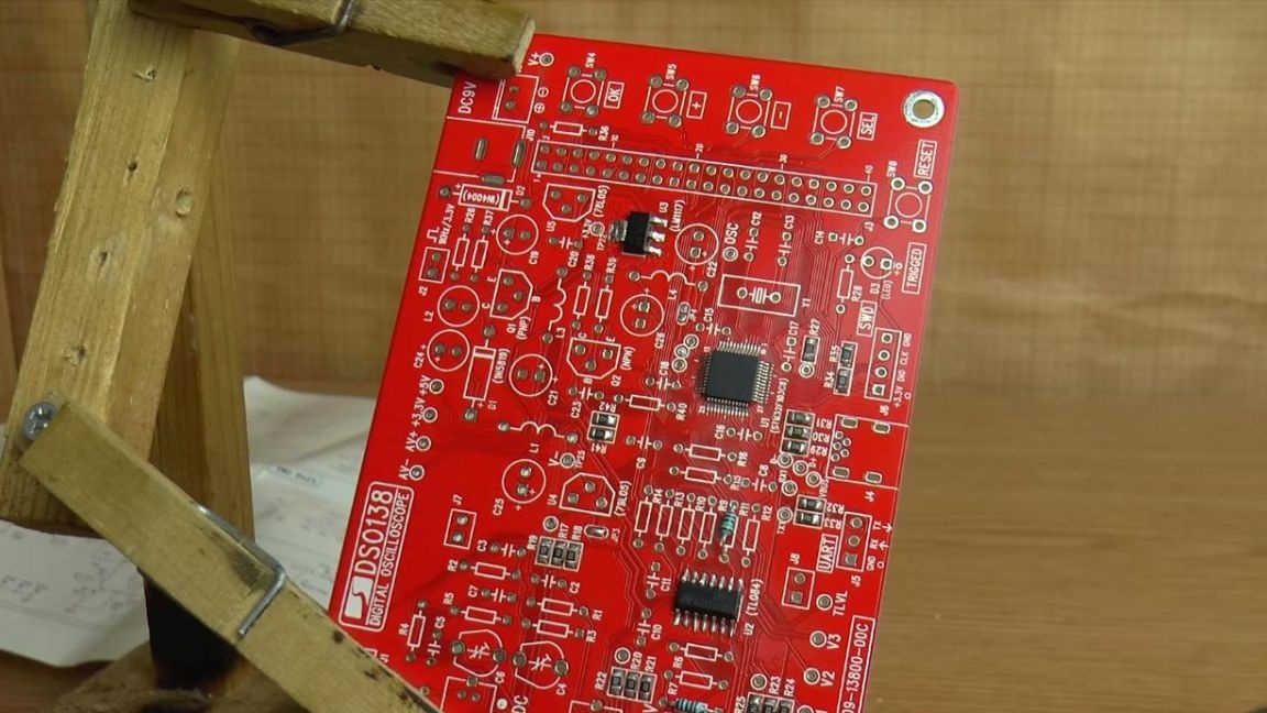
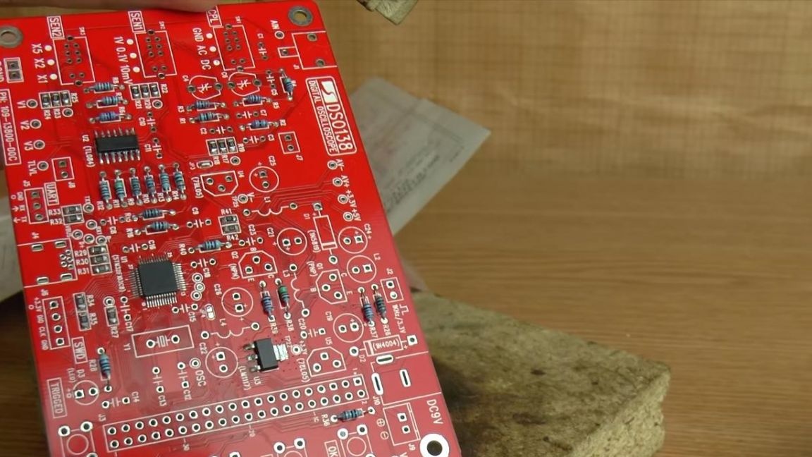
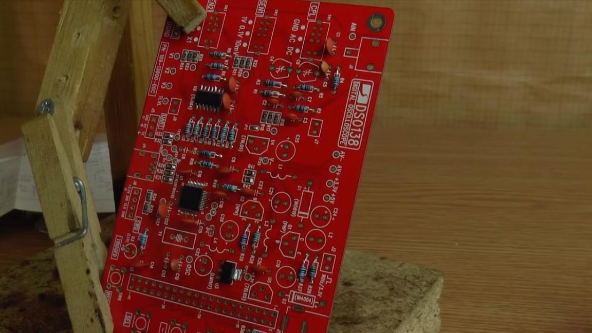
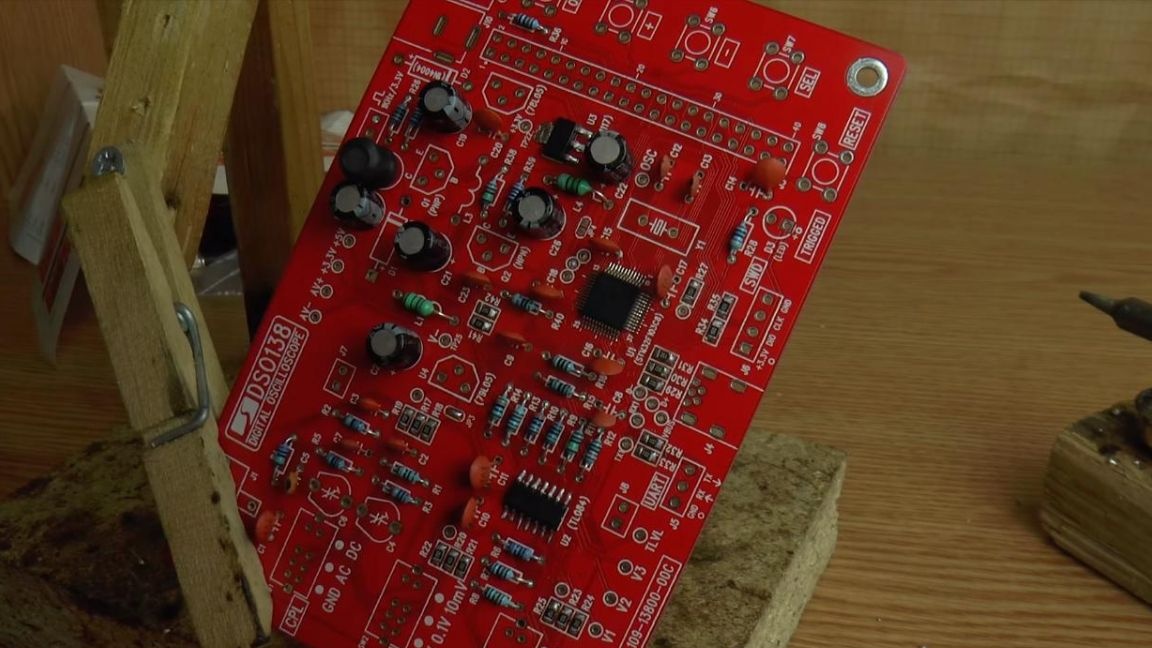
It looks like a board with soldered resistors.
Step Four
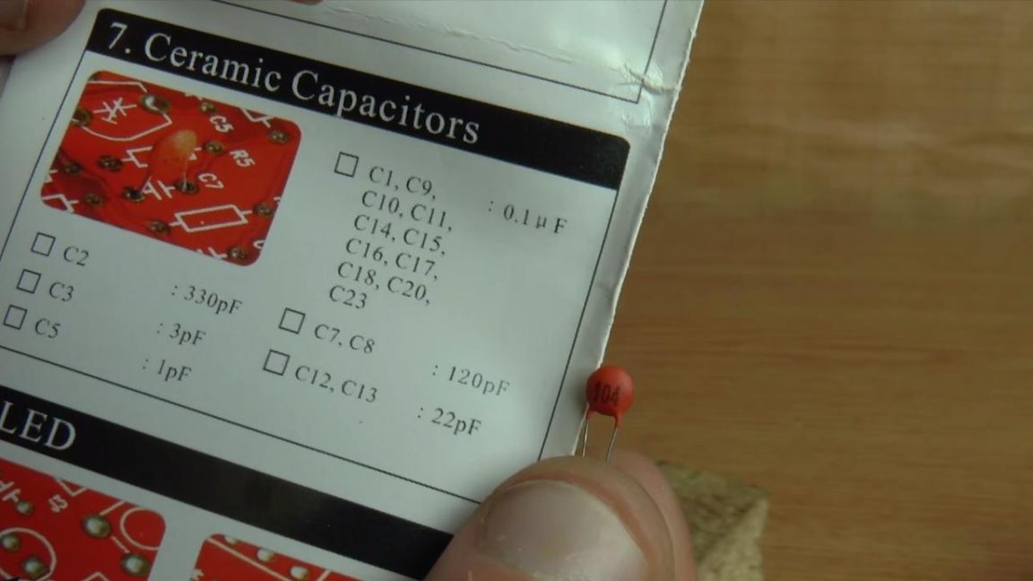
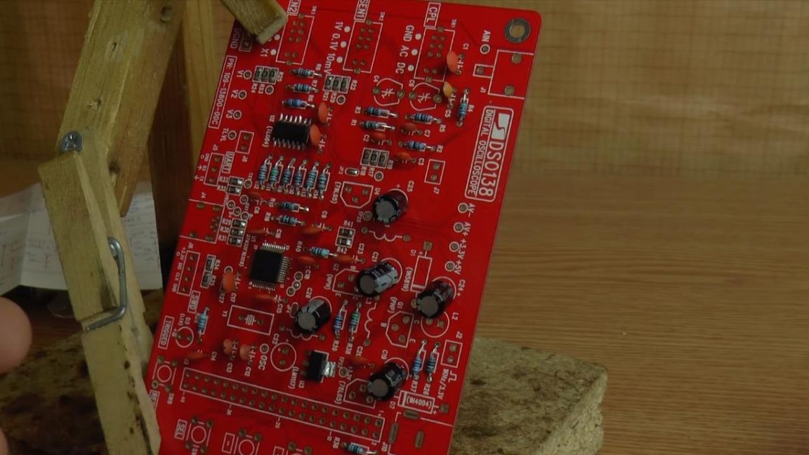
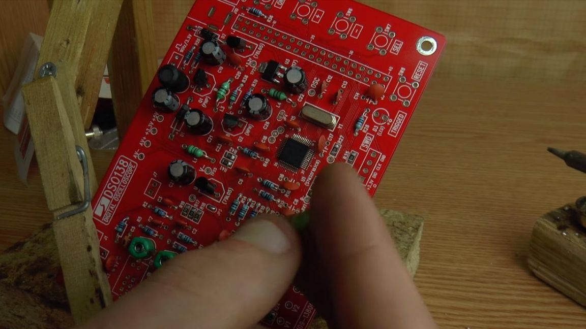
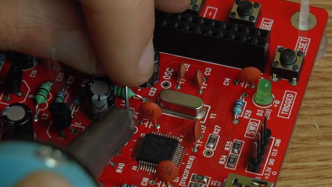
The resistors are installed, followed by soldering non-polar capacitors, the markings of which are indicated on the case by a number, for example, a capacitor with 104 number on the case has a rating of 10 * 10 to 4 degrees, which means its capacity is 100,000 picofarads = 0.1 μf, we have them on the board according to the instructions.
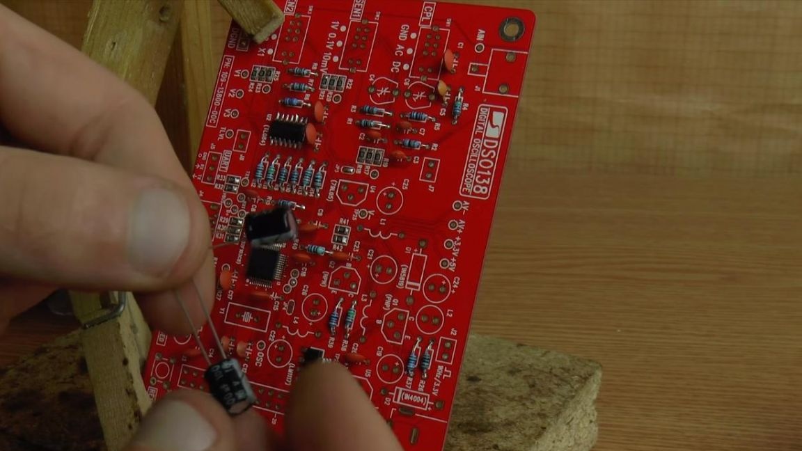
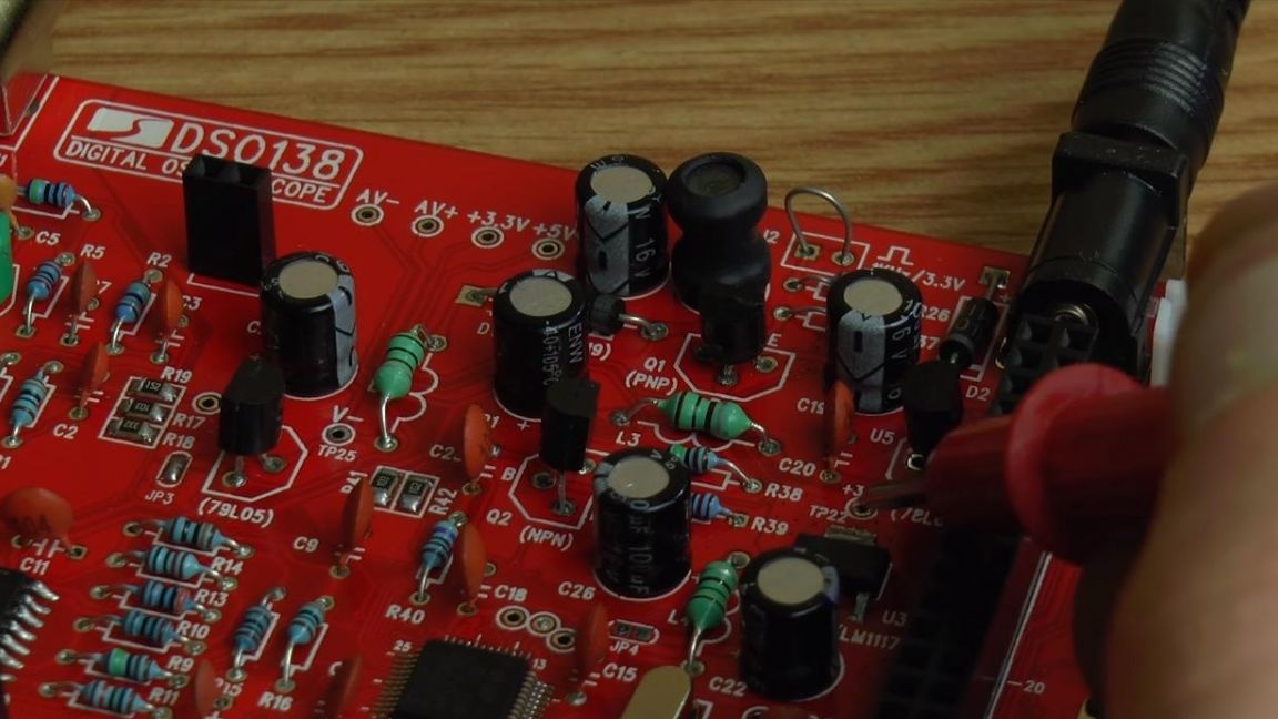
Next, we insert the polar capacitors, on their case the negative contact is indicated by a white strip, and the plus is the long leg. A plus is also signed on the board itself, the ratings are checked according to the instructions.
Step Five
We have inductors on the board, you do not have to determine their values, since they are all the same. Install them according to the instructions, then solder them on the back of the board.
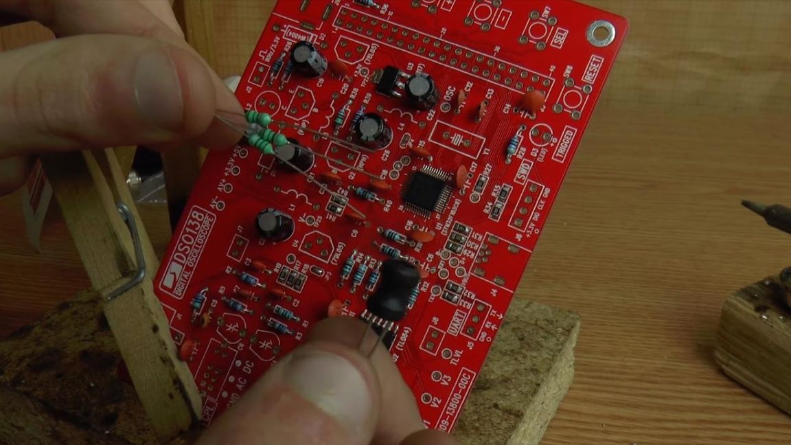
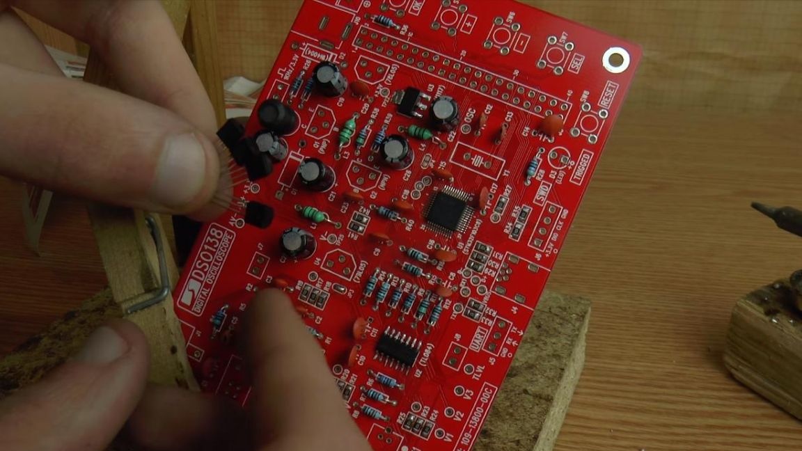
Now we insert the transistors, their number is indicated both on the case and on the board, it shows a drawing that repeats the shape of the case, according to which you need to install them, then solder their findings to the contacts.
Two diodes also came in the kit, they need to be installed according to the marking on the case, as well as the strip, which is located on its edge and is depicted on the board with a white dash.
Step Six
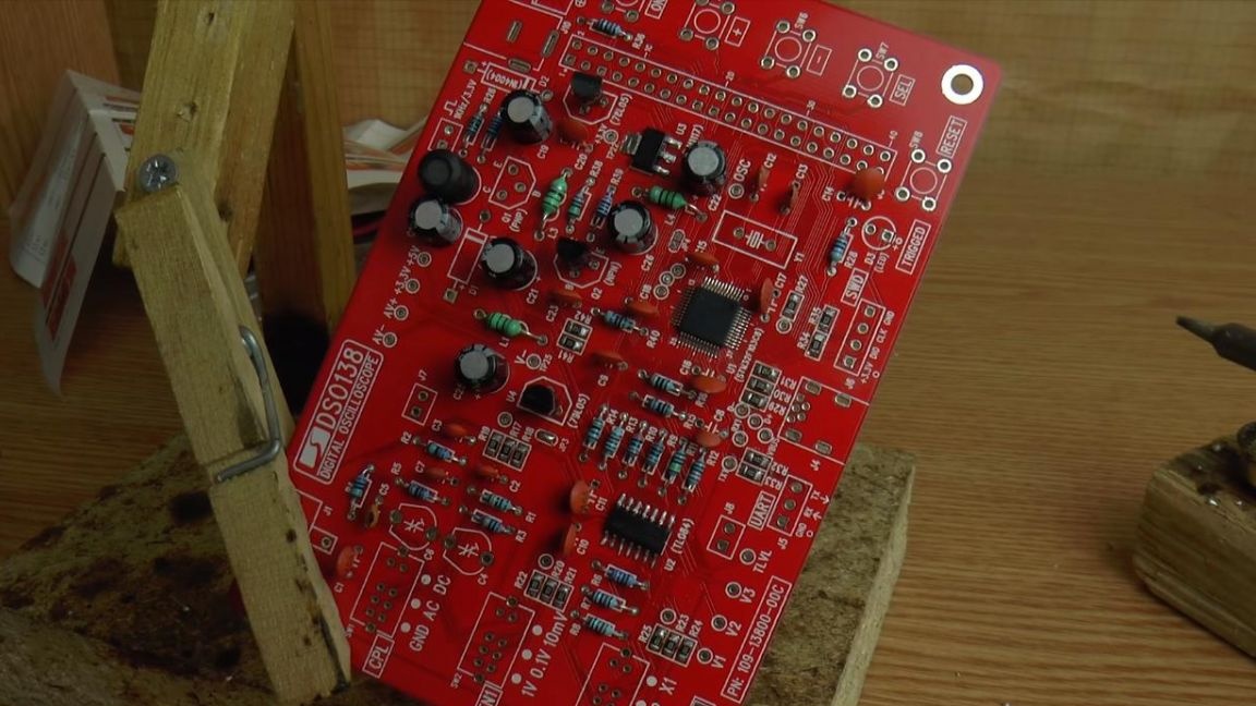
For indication, solder a single green LED, the long leg is a plus, a short minus, on the board for installation a plus contact is marked.
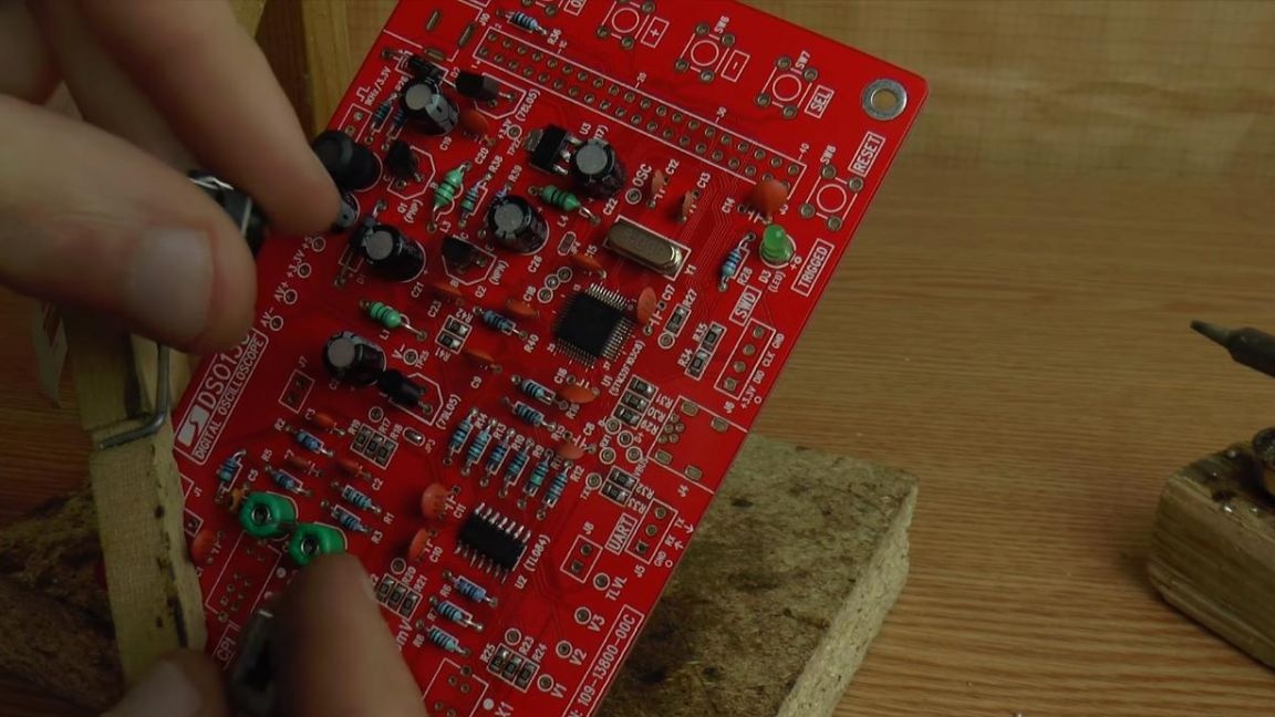
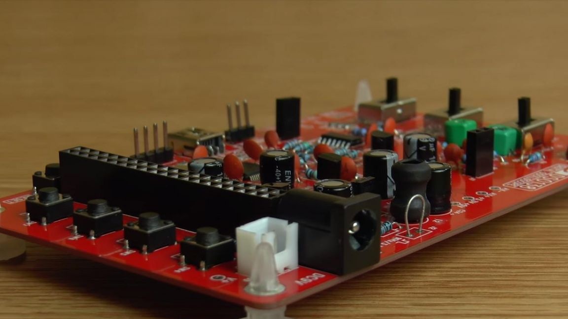
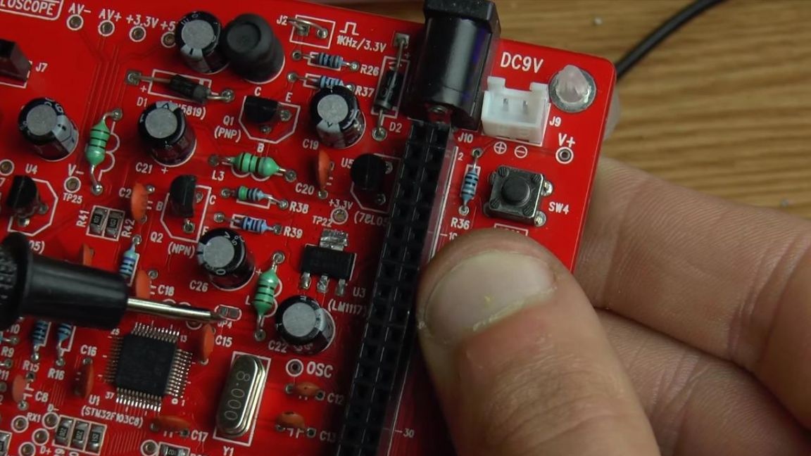
Almost all the parts are already installed on the board, it remains to solder the connectors, buttons and switches.
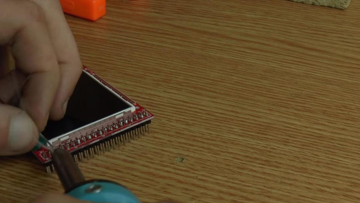
Next, solder the contacts to the display, with which they will connect to the oscilloscope board.
Seventh step.
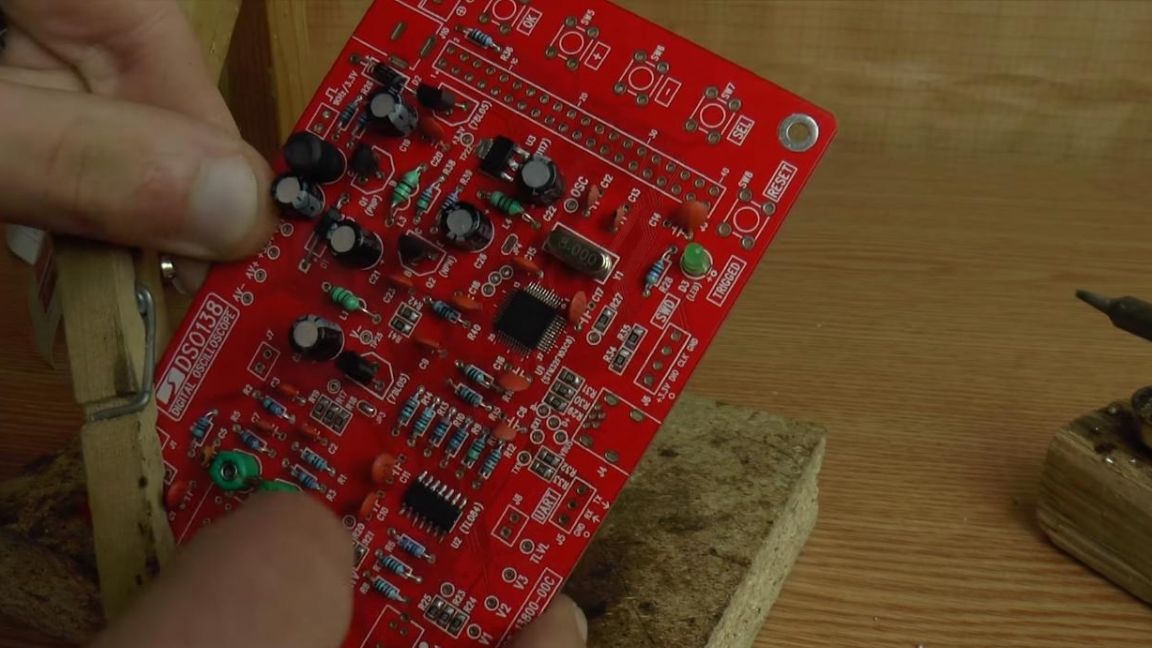
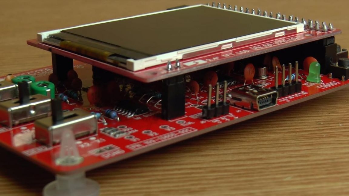
The board is completely ready, we put it on special plastic legs from the kit.
Now you need to make a jumper in place of JP3.
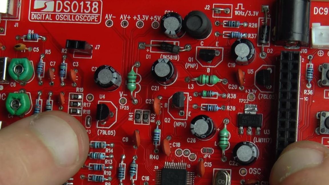
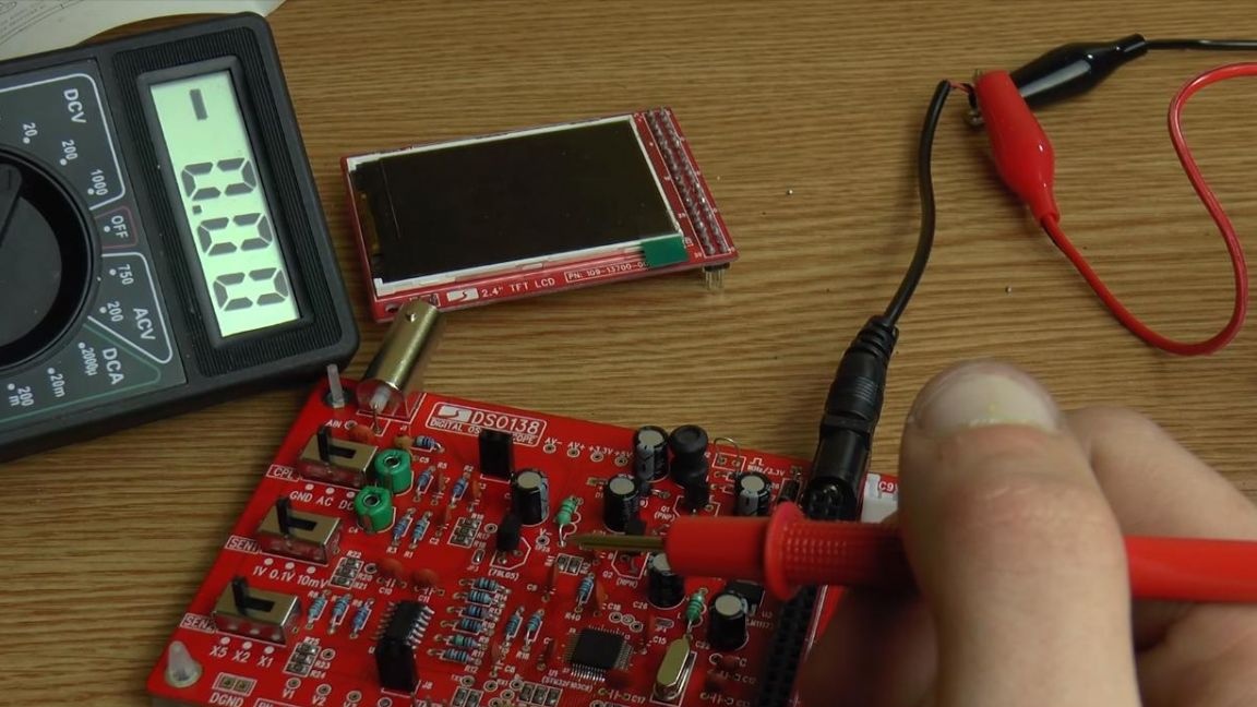
Before connecting the display to the board, you need to check the assembled device, for this you will need a multimeter. We connect the 9 V power to the device and in the voltage measurement mode, set the minus probe of the multimeter to the contact on the board labeled GND, and the plus to the 3.3 V contact, which is located just above the SMD transistor, the multimeter should have such voltage, i.e. equal to 3.3 V.
After this check, disconnect the power and make a jumper in place of JP4, and then install the display module.
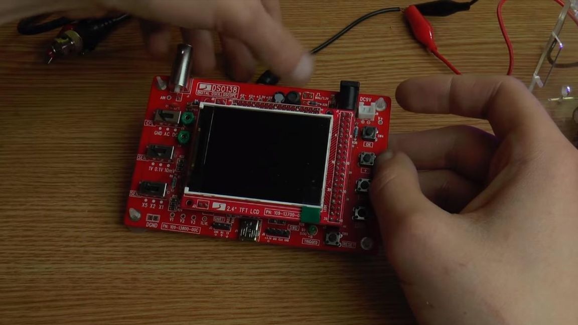
Step Eight.
Since the device has not yet been configured, it is impossible to work with it, so for a start we will configure.
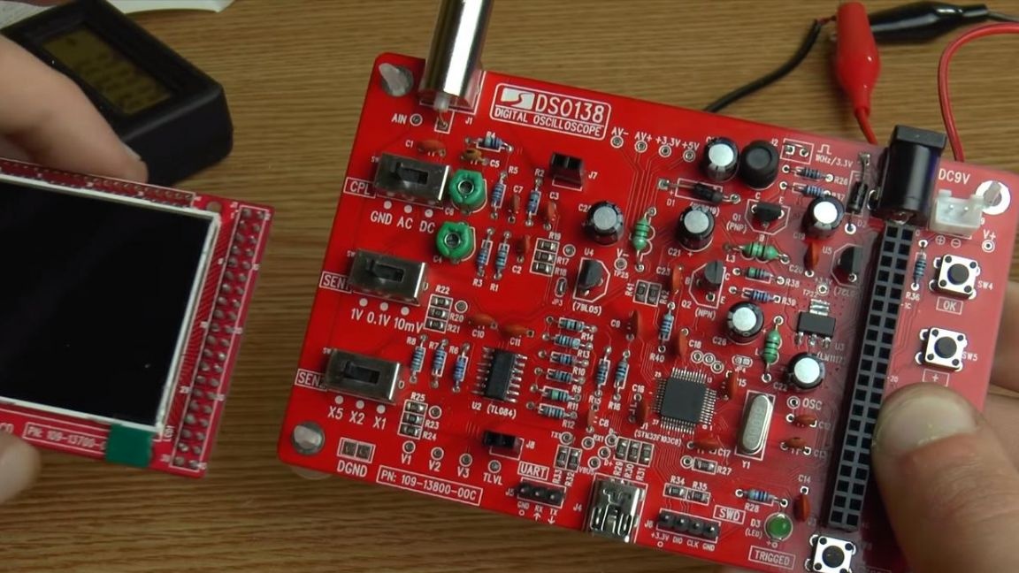
We turn on the oscilloscope and set the second switch to 0.1 volt, the lower switch to X5, which is responsible for the divider, and the upper switch to DC.
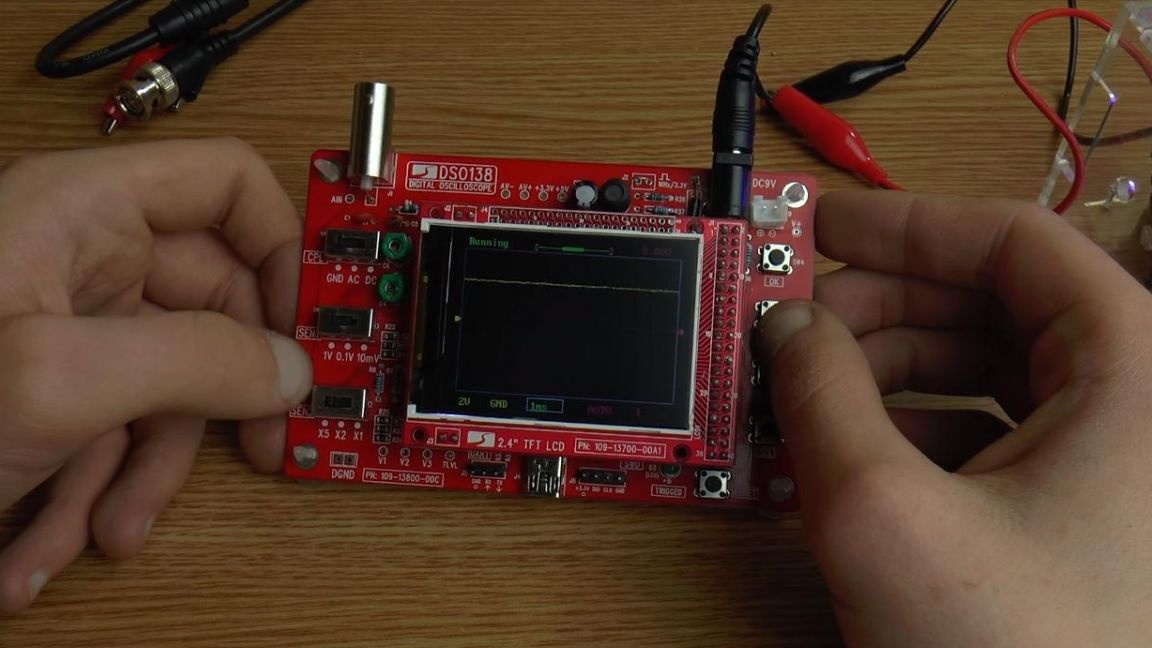
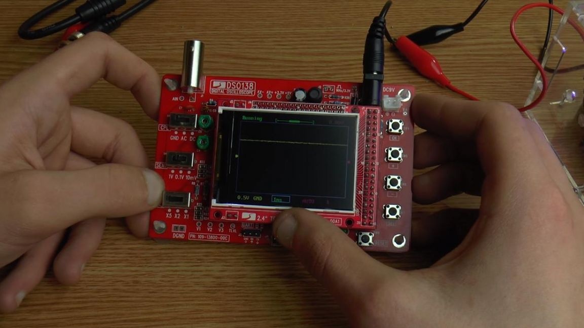
A positive crocodile is connected to the control point in the form of a jumper. We move the curve a little lower, click on the lower right button, thereby switching to the left slider, which can now be adjusted with the middle buttons + or -.
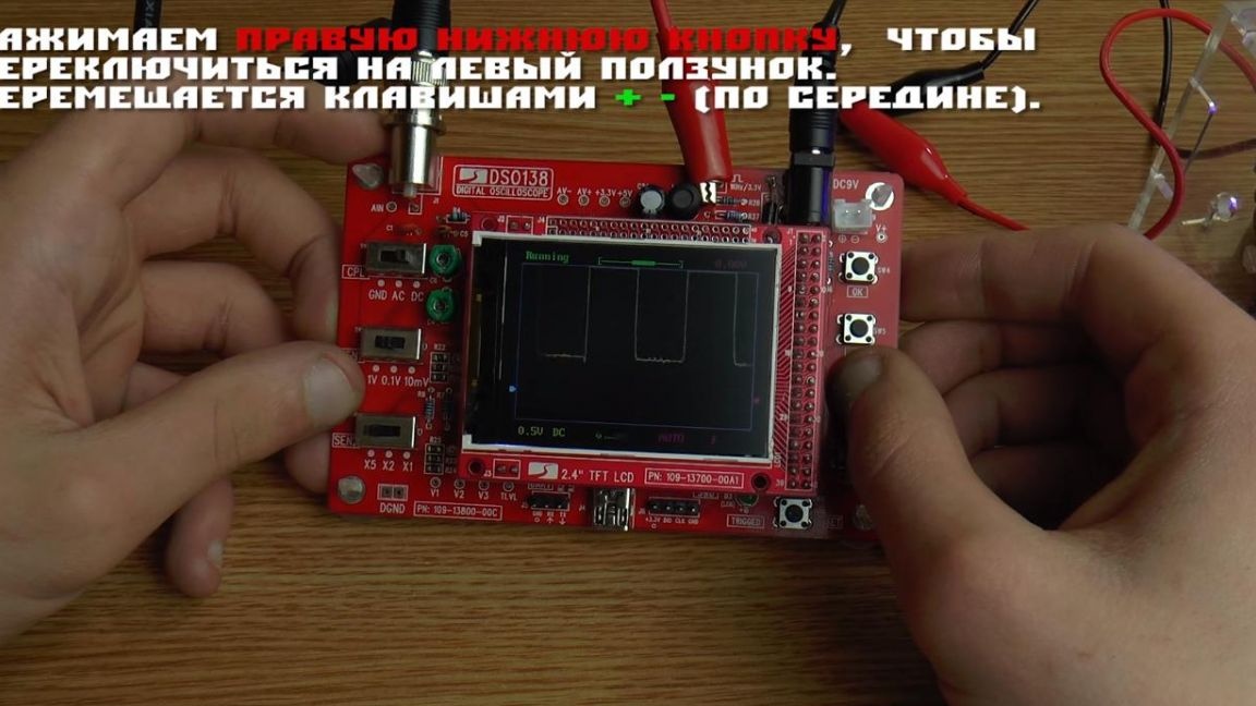
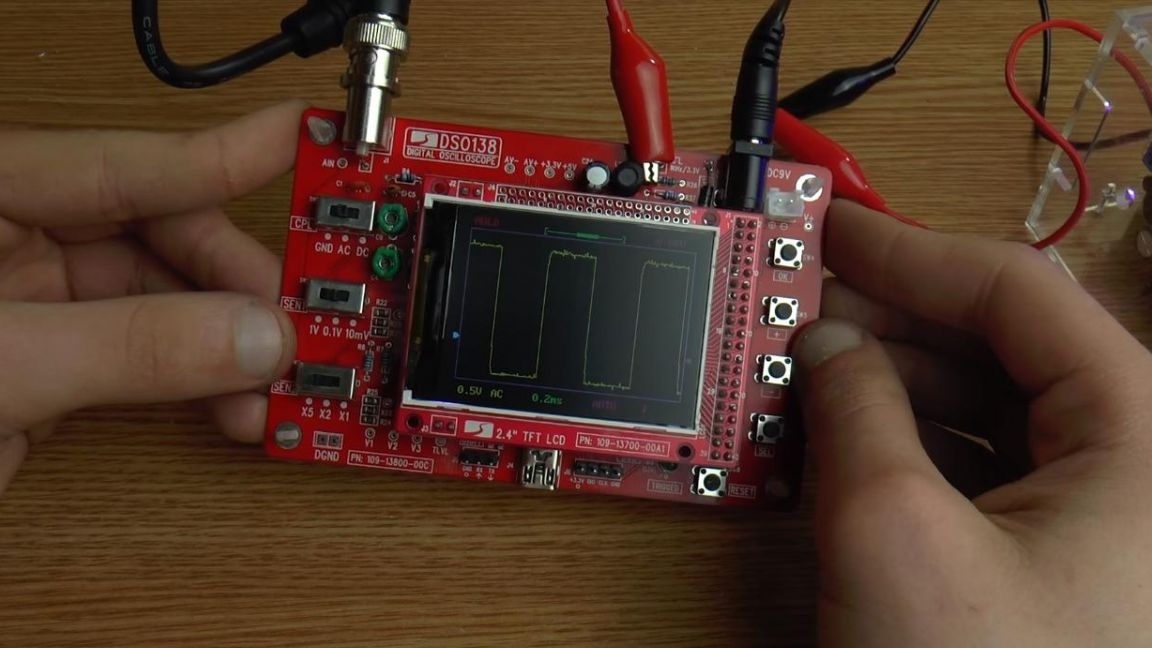
We set a smoother line on the graph by adjusting the capacitance of the variable capacitors, we do this with a screwdriver.
Step Nine.
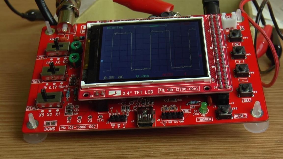
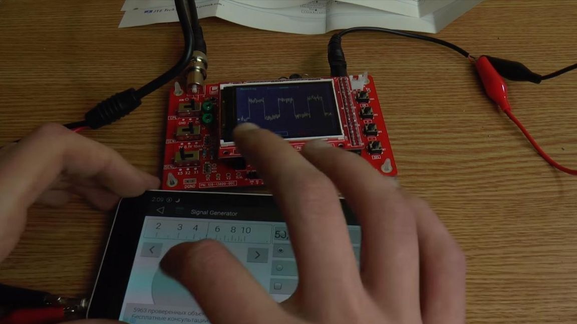
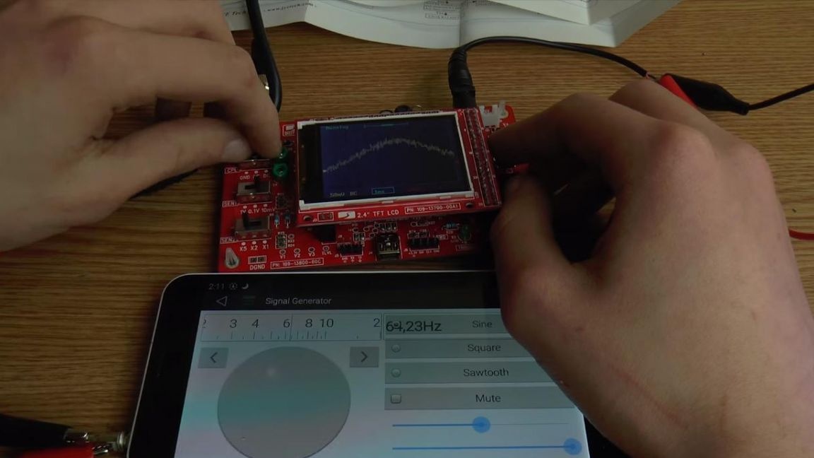
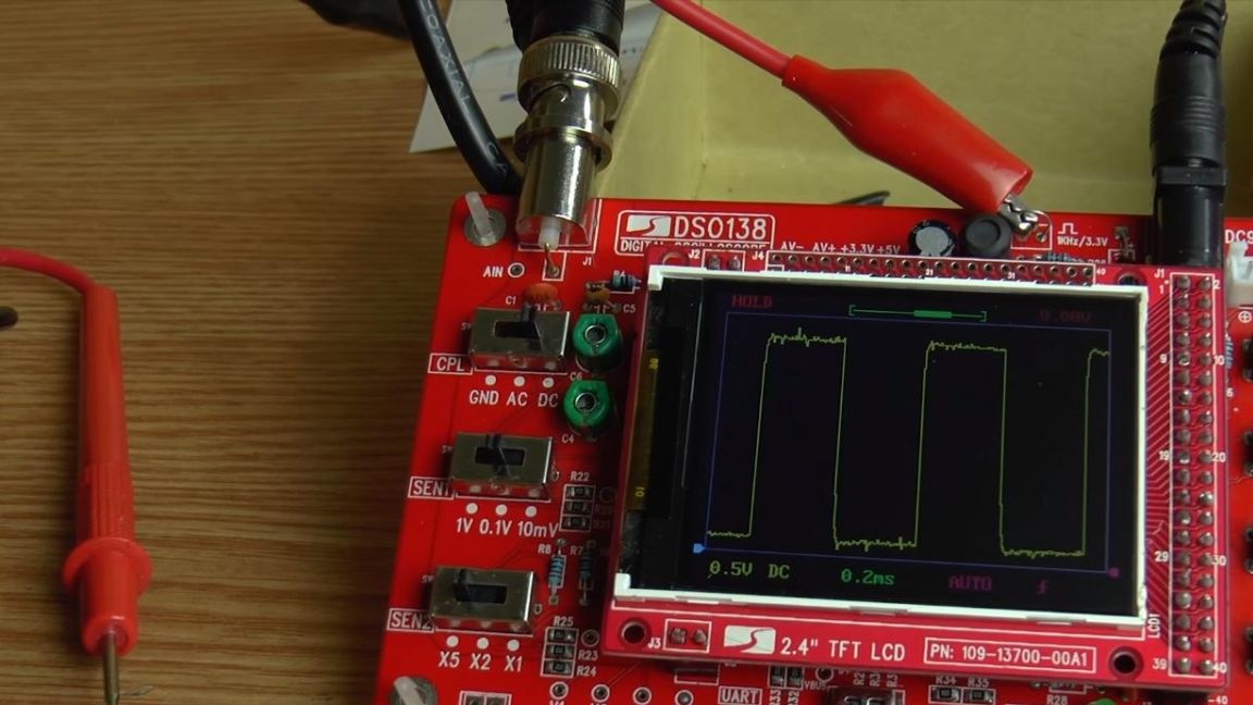
Now you can connect the phone with the signal generator program through the audio output to the oscilloscope probes.
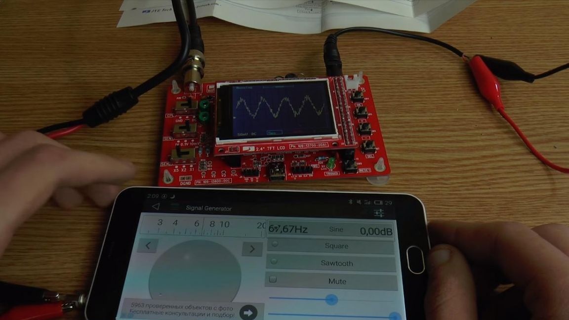
On the phone we change the frequency, on the device’s display we see a graph that you can zoom in and out and change other settings, a complete instruction on how to use it is also included.
For hams, this kit kit will definitely be useful, especially if it is assembled with your own hands.
That's all for me, thank you all for your attention and creative success.