
Hello to all lovers homemade. In this article I will tell you how to make a Hi-Fi microphone amplifier. do it yourself, in the assembly of which the kit kit will help us, which you can order from the link at the end of the article. With it, you can amplify the signal from two microphones, as well as use as a preamp in the audio system.
Before reading the article, I suggest watching a video with a detailed assembly and testing of the kit.
In order to make a microphone amplifier with your own hands, you will need:
* Kit
* Soldering iron, solder, flux
* Side cutters
* Device for soldering "third hand"
* Power supply 9-18 V
* Microphone
* Amplifier and speakers for checking
Step one.
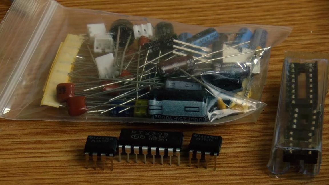
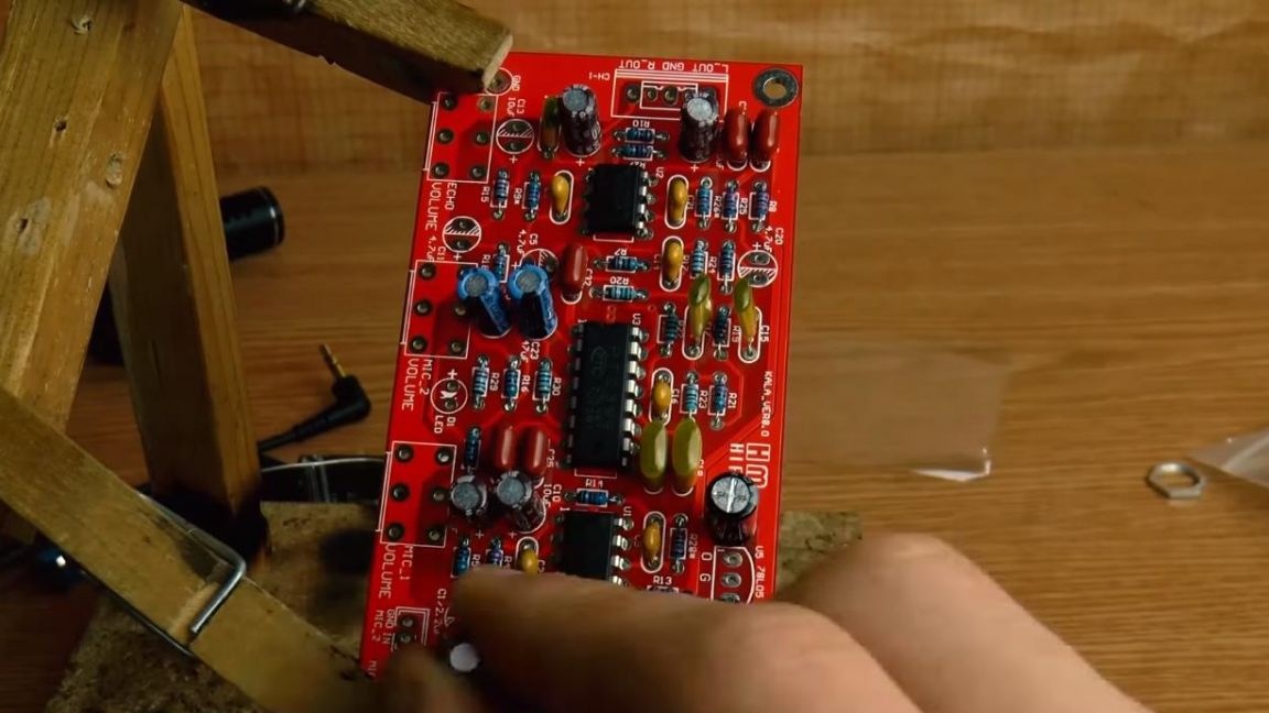
Let's take a closer look at the kit, and start with the kit itself.
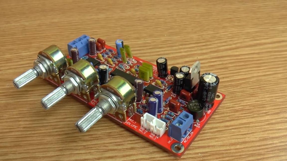
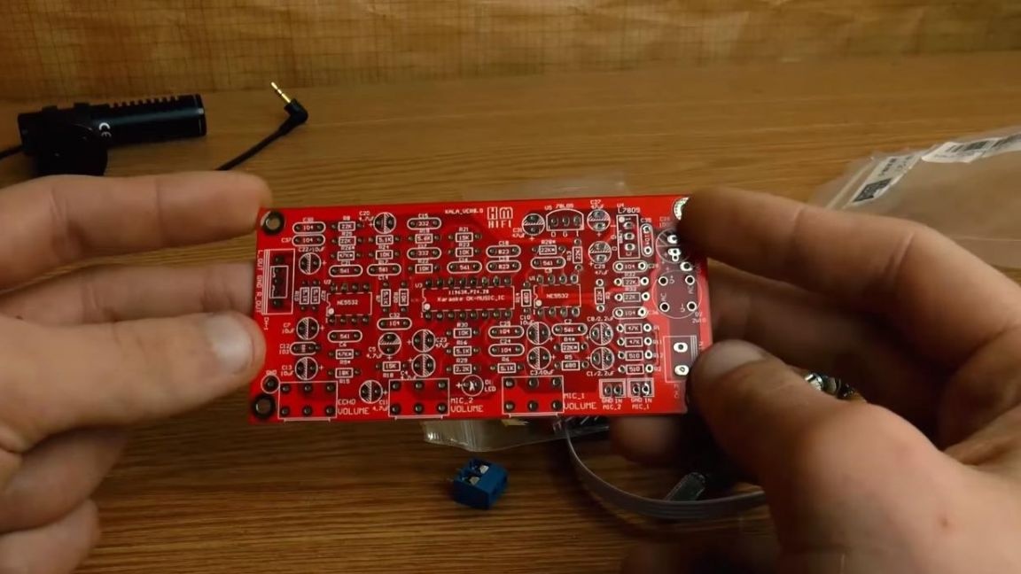
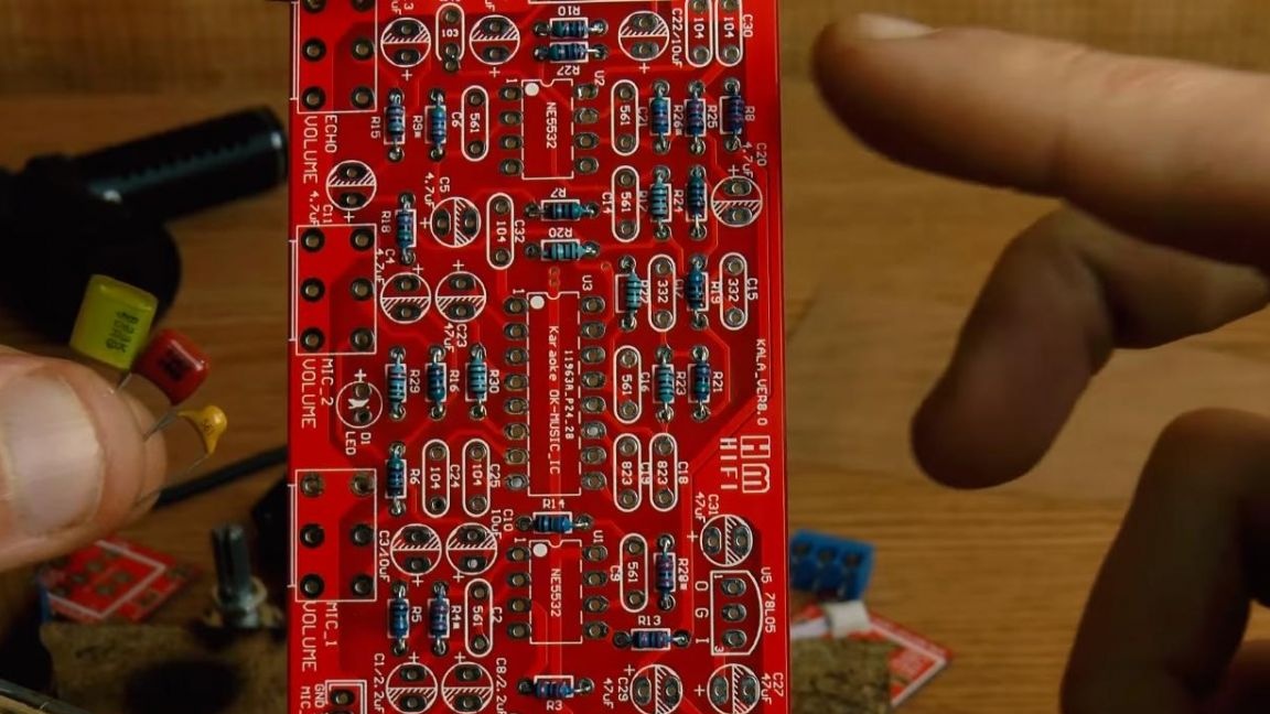
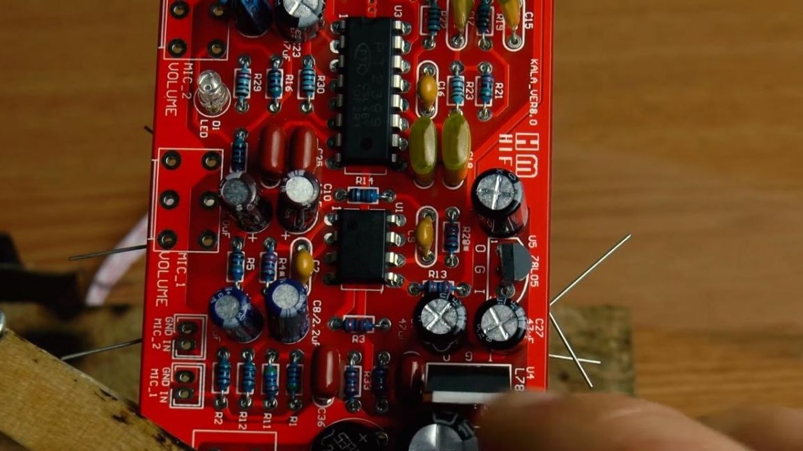
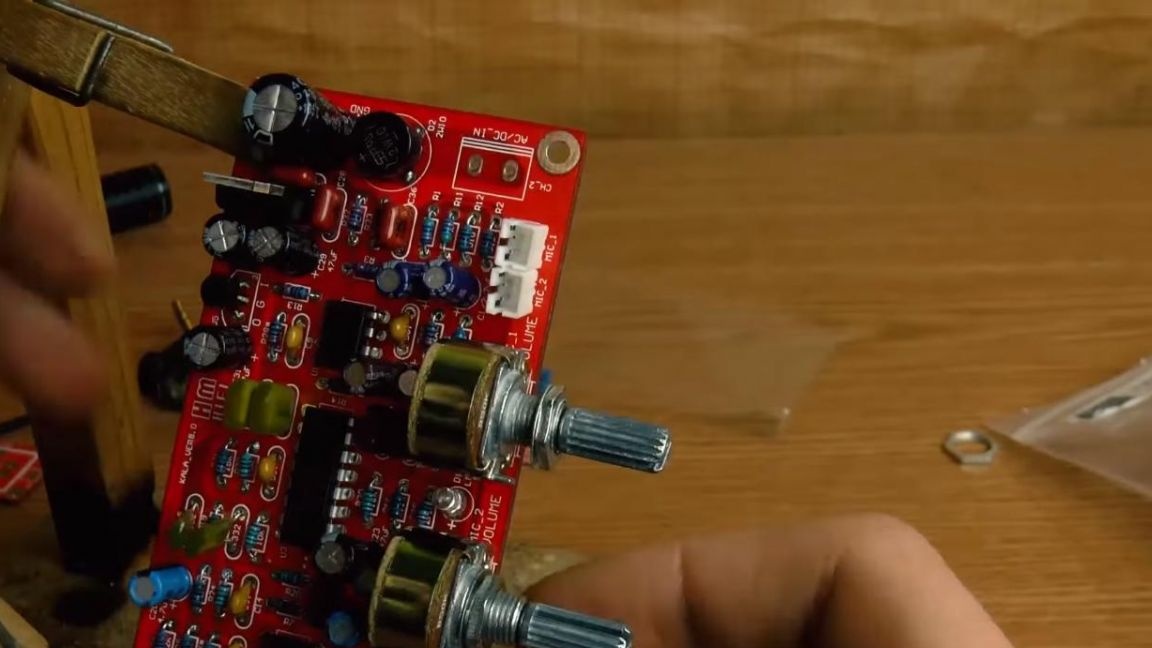
This kit kit comes with a fairly large set of radio components, packaged in a package that has a double-sided printed circuit board with metallized contacts of good quality, it is marked for convenience, since there are no instructions for the kit.
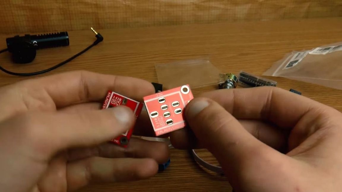
There are also two smaller boards, they serve to connect a microphone plug, and there are holes at the edges to install them in the case.
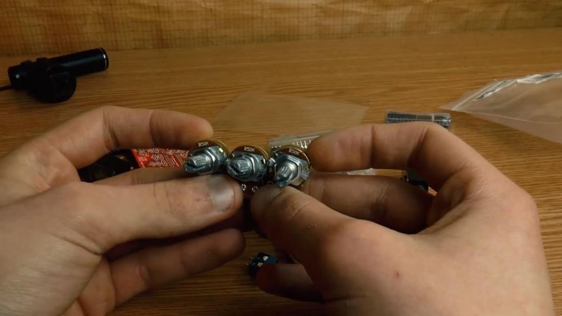
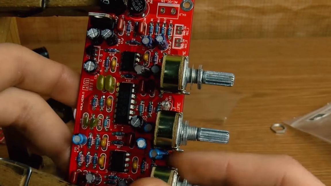
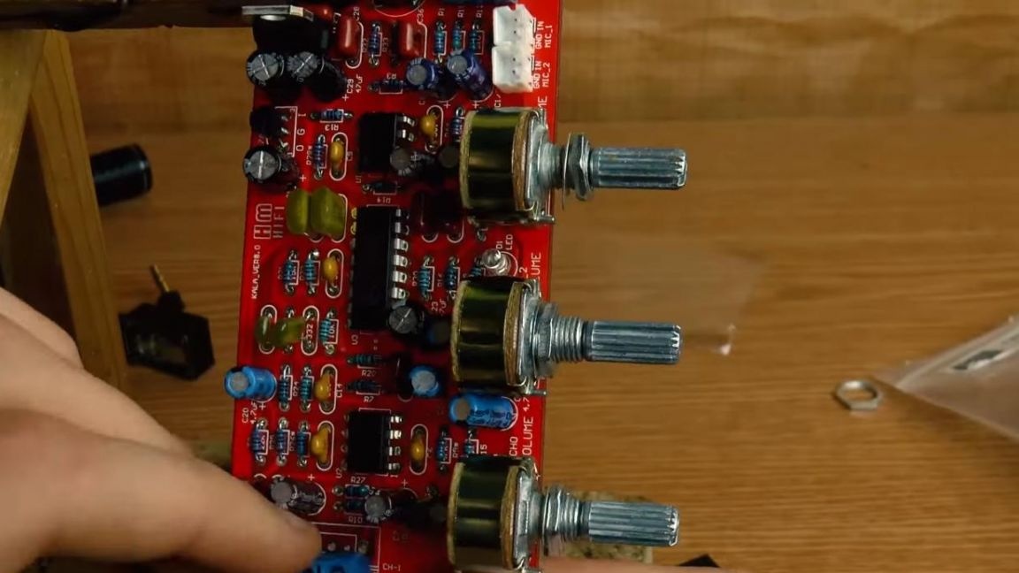
To adjust the volume level, echo level and balance, three variable two-channel resistors were put into the kit.
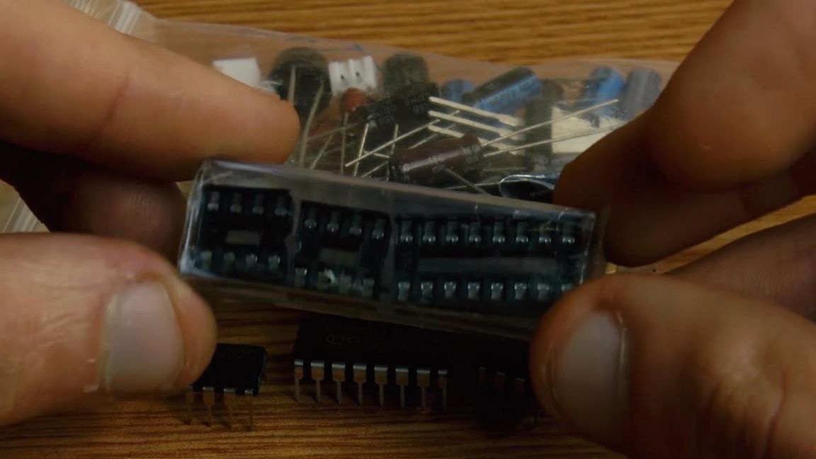
This kit kit works on three microcircuits; there are special DIP panels for them.
Step Two
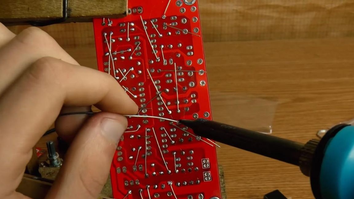
First, install the board in the soldering device "third hand" and arrange the resistors.
The values of the resistors on the board are signed, as well as on the papers themselves glued to the resistors, so this multimeter is not needed in this assembly.
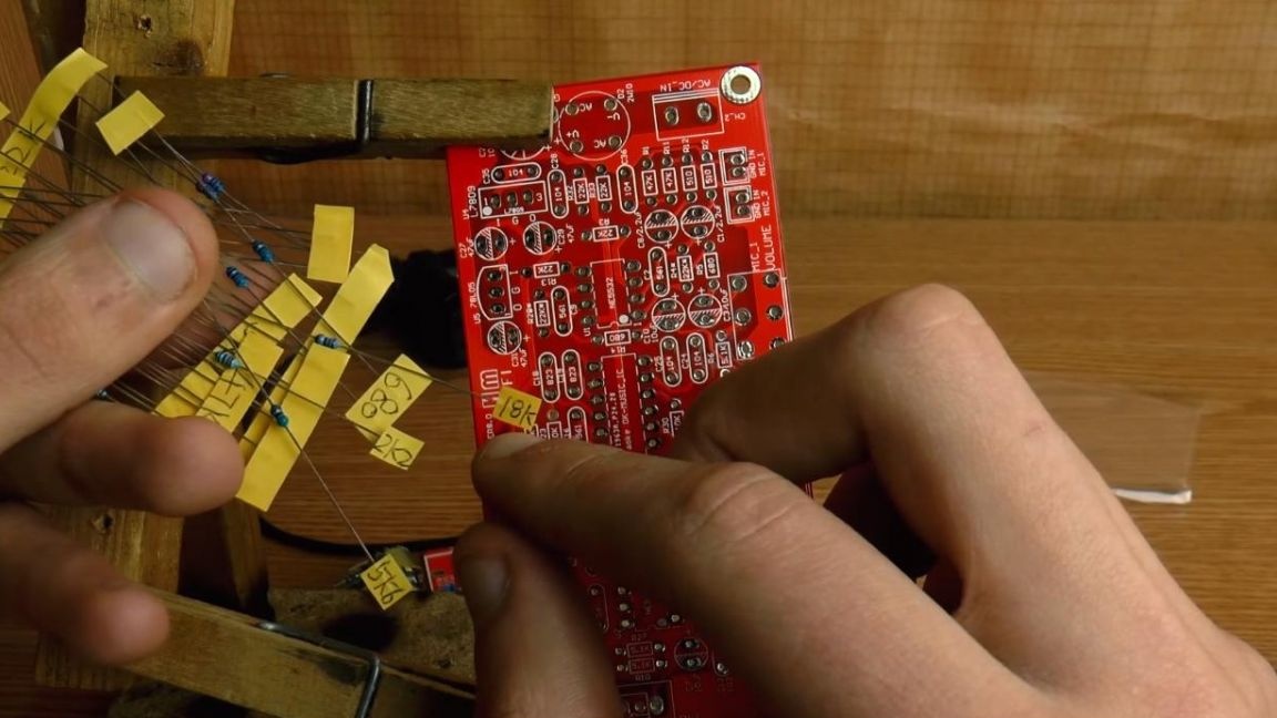
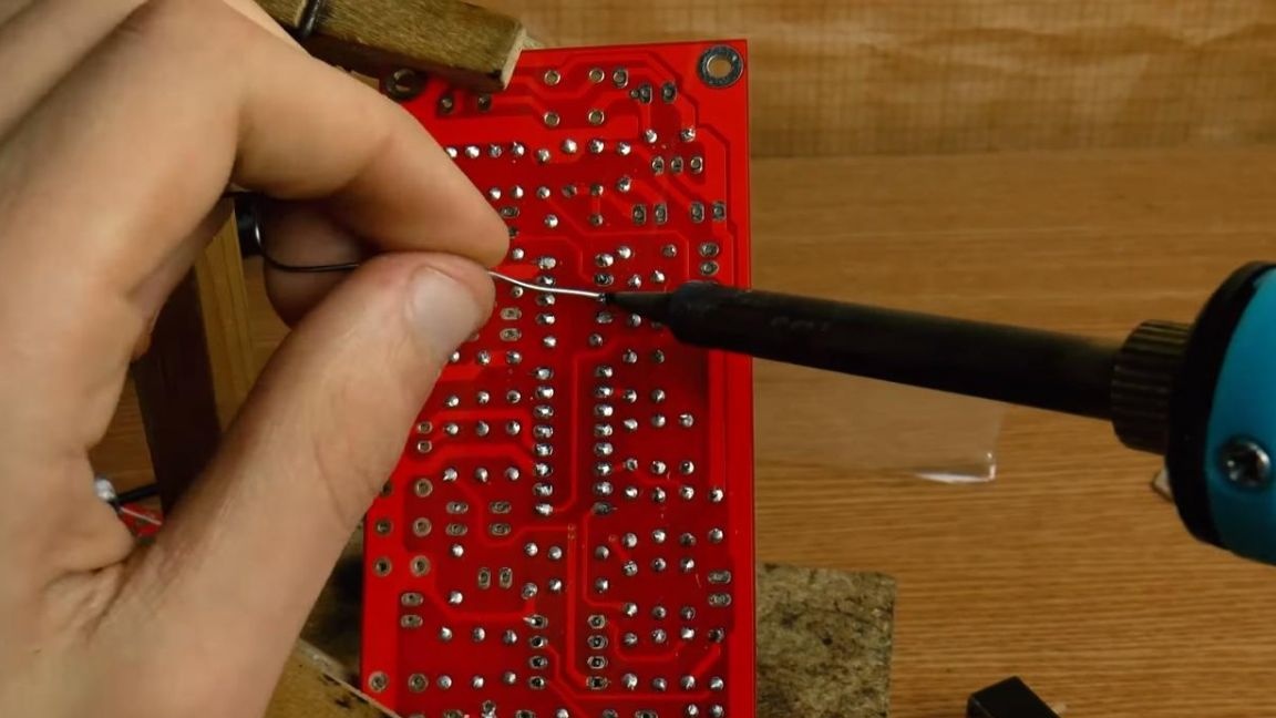
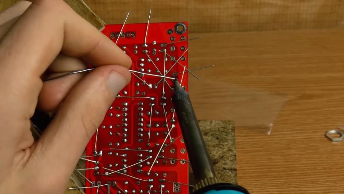
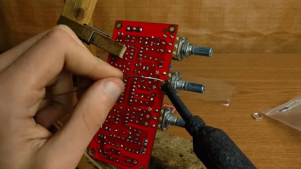
On the reverse side of the board, we bend the conclusions so that when soldering the radio components do not fall out. Next, we fix the board with the back side and apply the solder flux, and then solder the conclusions.
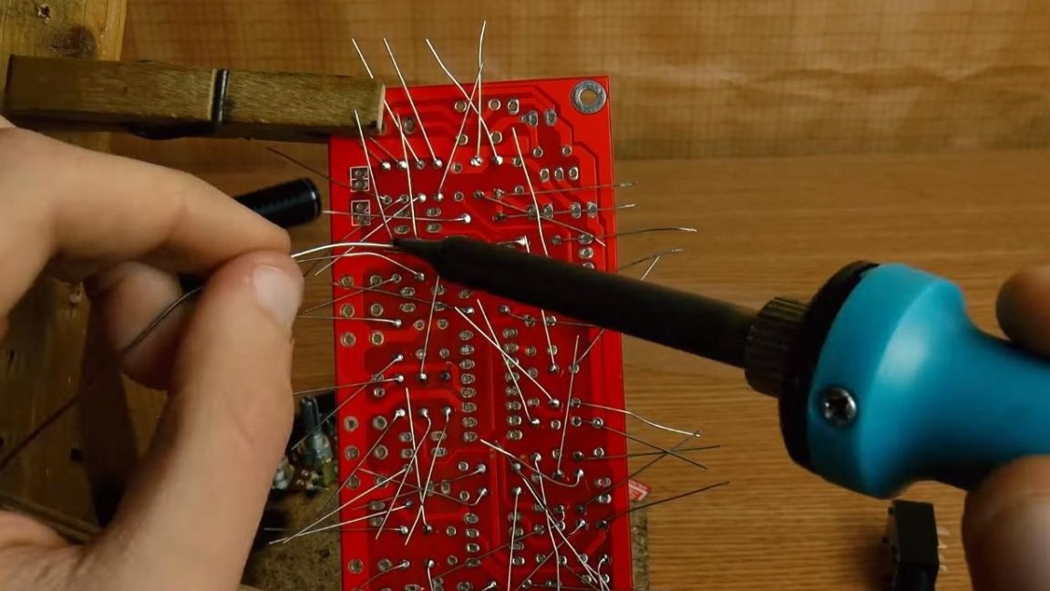
After soldering, bite off the findings with side cutters so that they do not interfere with the installation of the remaining components. Be careful at this stage, as you can accidentally tear tracks from the board with side cutters.
Step Three
Now we install non-polar ceramic capacitors, their values and name are signed both on the case and on the board itself, which is quite convenient, since they won’t be confused in places.
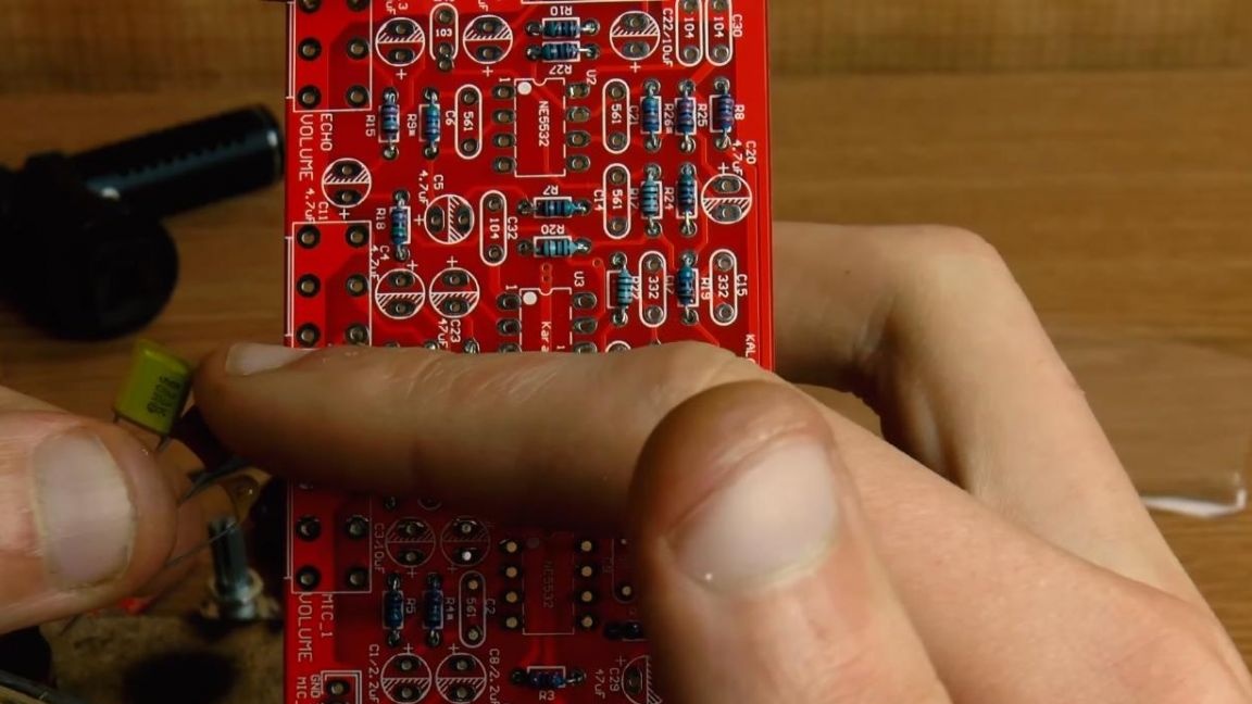
Similarly, solder all the conclusions and remove their remains with side cutters.
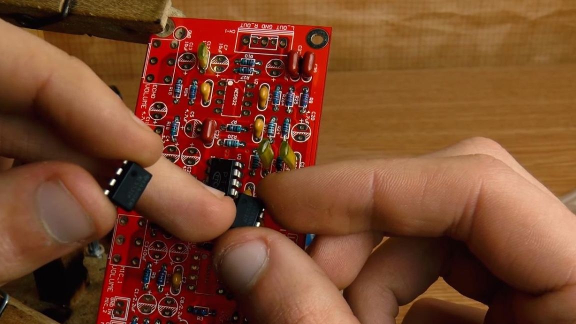
Step Four
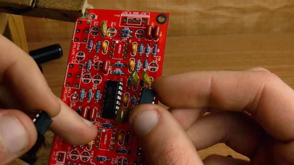
It's time to put the microcircuit in its place, their marking is indicated on the case and on the board. We combine the key on the microcircuit in the form of a semicircular recess with the same key on the board.
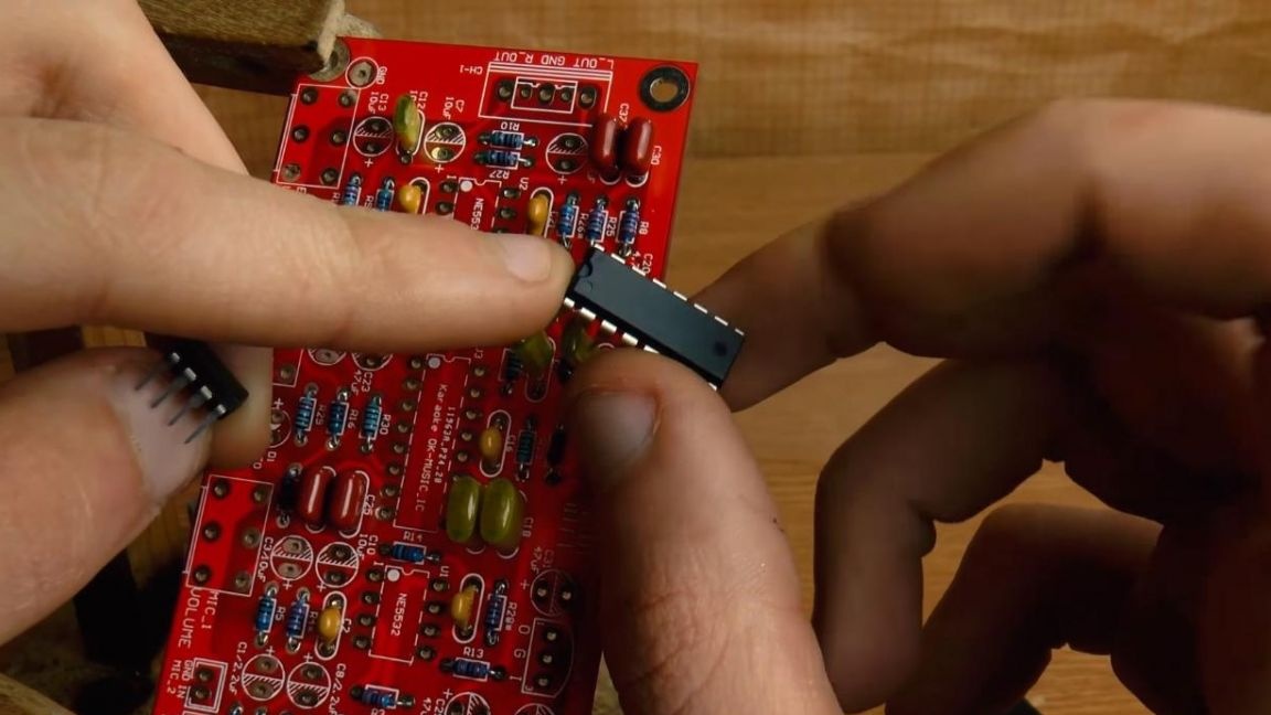
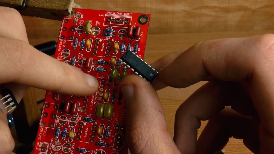
The other two smaller microcircuits have a slightly different key, made in the form of a circle near the first contact on the case, which is also indicated by the marking on the board, according to this, we install them on the board and solder them. When soldering chips, try to do this as quickly as possible so as not to overheat the conclusions and the chip itself, which can damage it.
Step Five
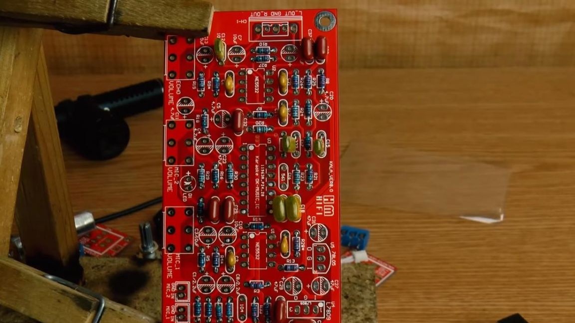
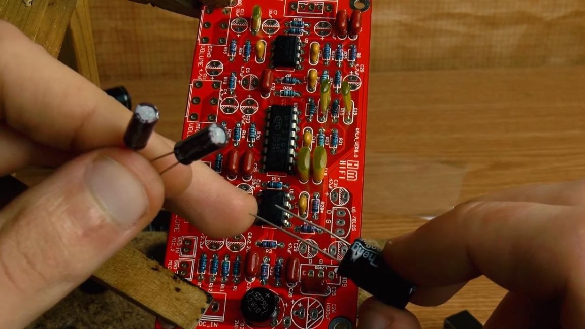
On the diagram, a place is allocated for the diode bridge, plus and minus are signed on its case, as on the board, we combine them and insert them into the holes of the board, slightly bending the conclusions.
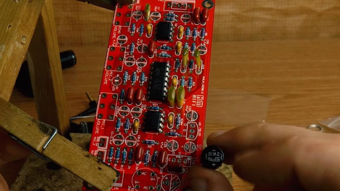
Next, according to the ratings and polarity, we install polar electrolytic capacitors, on the board the minus is indicated by hatching, and on the capacitor itself the negative terminal is opposite the white strip on its case, and plus, as always, this is a long terminal, the ratings on the board are also signed.
Step Six
For indication on the board, an LED is provided, we insert it according to the polarity, on the board there is a positive contact, on the LED it is a long output, and a short one is a minus.
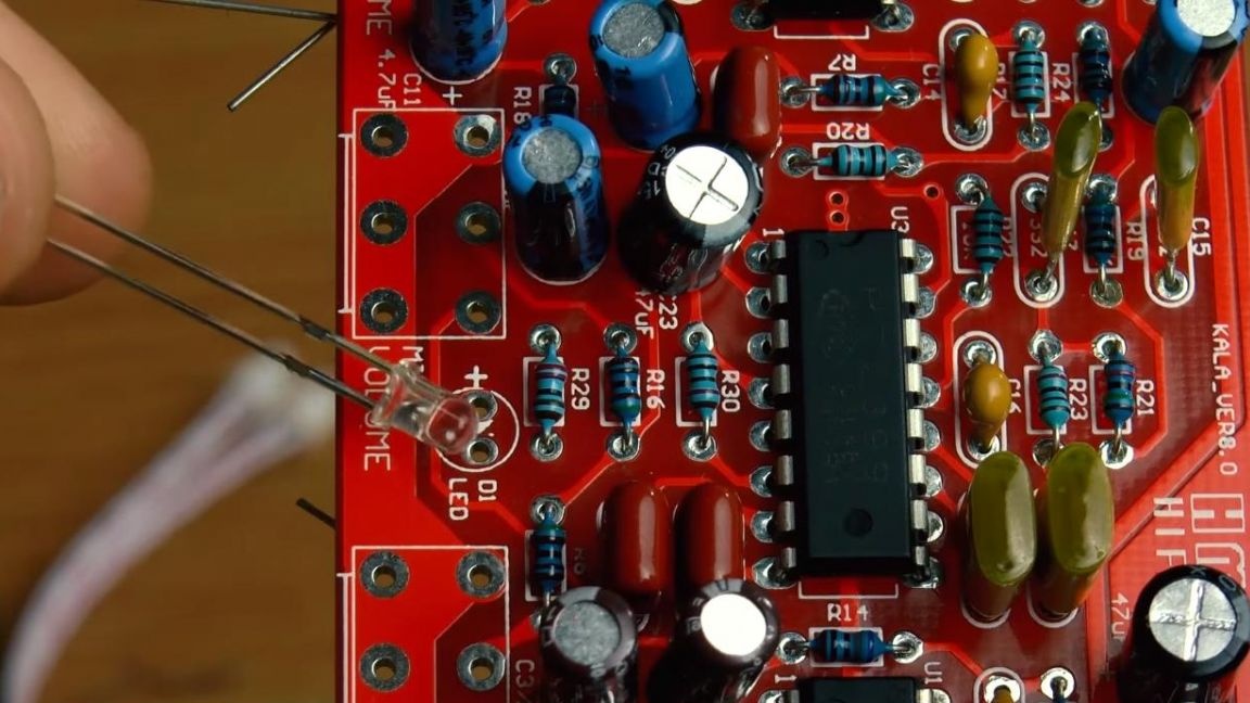
Now we put the transistor, we are guided by the marking, which is similar to the case, we combine and install in place.
Then we insert the stabilizer, guided by the first leg, their positions are indicated by the numbers on the board.
After that, solder the findings of the components and remove their remnants with side cutters.
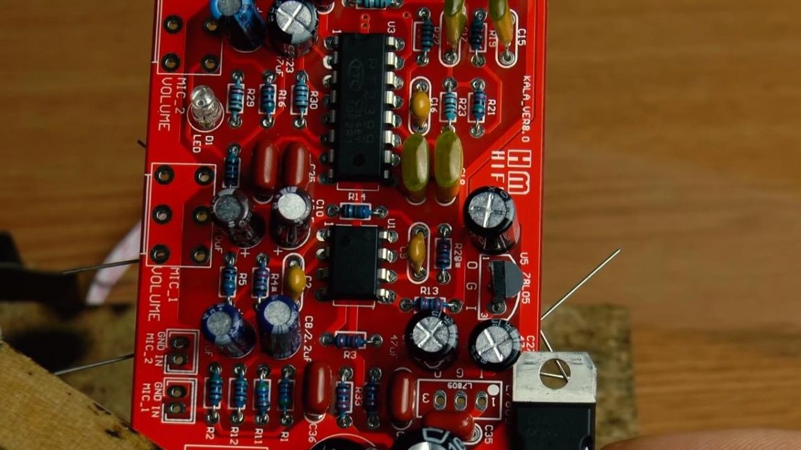
Seventh step.
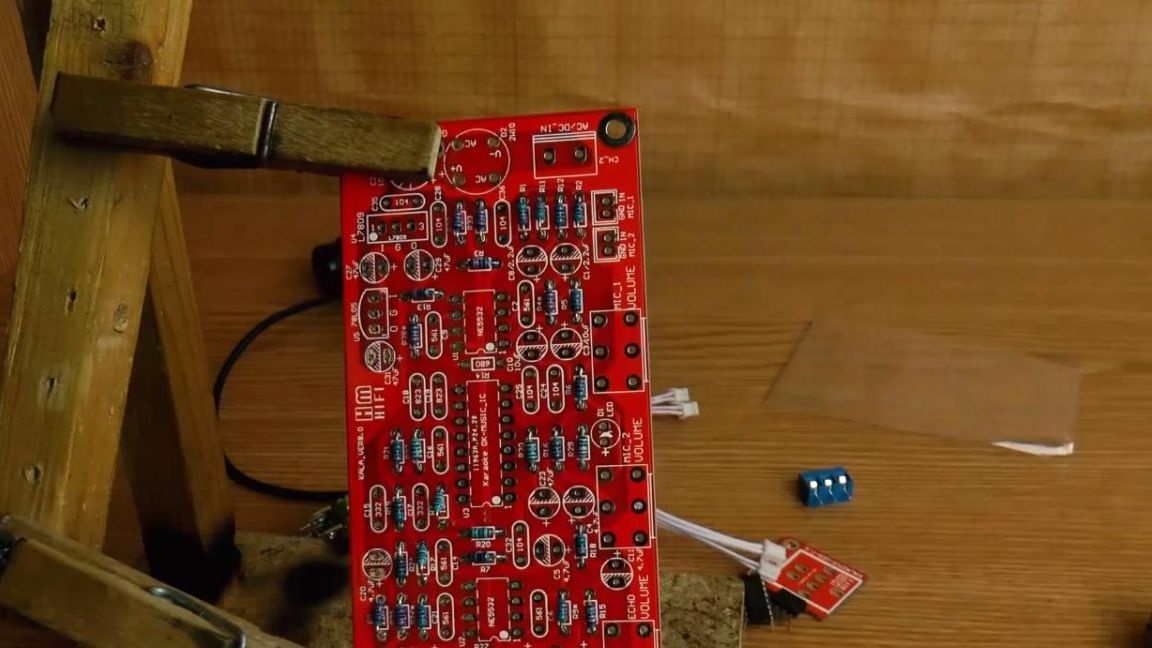
There is very little left. We put three variable resistors, jacks for connecting microphones and terminals for connecting power and output from the amplifier to the board.
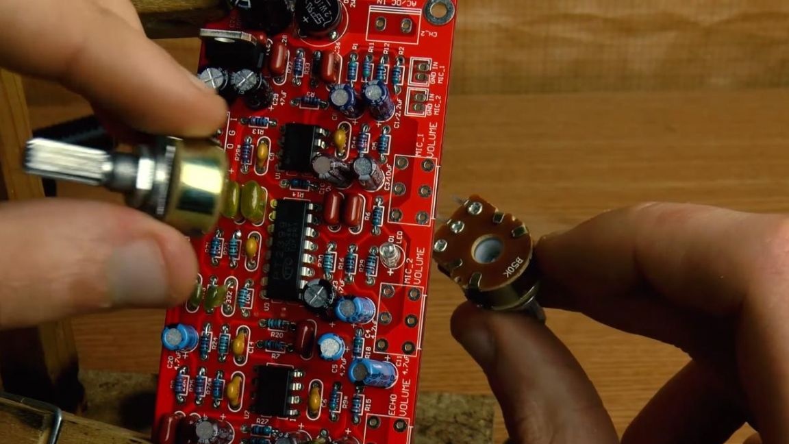
After that, solder the components.
This completes the assembly of the microphone amplifier, now you need to check it in operation.
Step Eight.
To power the amplifier, you need a voltage from 9 to 18 V. We connect the power supply to the amplifier and check how it amplifies the signal from the microphone.
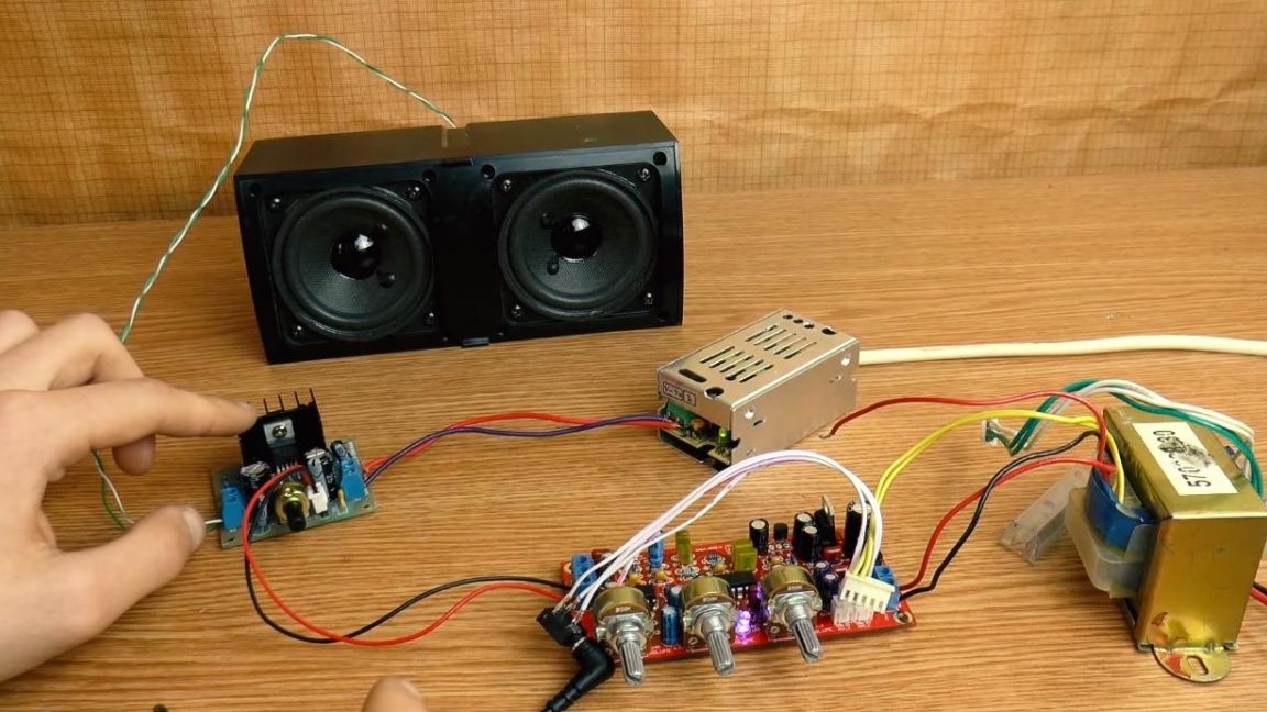
The microphone amplifier transmits sound quite qualitatively, but in this case it is still limited by the sound amplifier itself, which amplifies its output signal, so this also needs to be taken into account. This microphone amplifier can be used not only with microphones, but also as a pre-amplifier.
That's all for me, thank you all for your attention and creative success.