» Electronics » Metal detectors »Metal detector on the Arduino Pro Mini. Processing of the depths of the Kolokolov-Shchedrin according to the principle of “Transmission”

Metal Detector on Arduino Pro Mini. Processing of the depths of the Kolokolov-Shchedrin according to the principle of “Transmission”


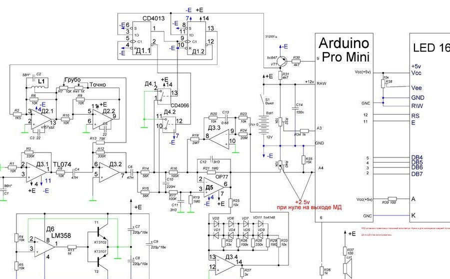
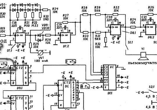
Recycling of the Kolokolov-Shchedrin deep-water scheme. Differences from the original scheme:
1. There is NO crystal oscillator on the k561 .. chip and 32 kHz quartz. The 32 kHz signal gives the Arduino Pro Mini.
2. Sound notification circuits on several 561 series microcircuits are also not present, Arduino is also voicing the target (And I must say, it is excellent voicing, in comparison with the author's scheme).
3. Powered by unipolar voltage 12v (lead-acid battery).
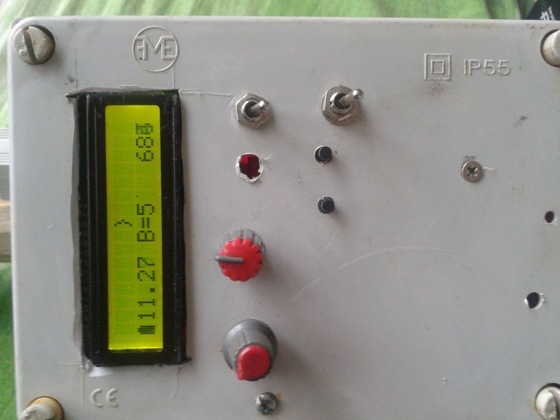
4. Adjust the sensitivity with the buttons. With the ADC scale from 0 to 1023, the response threshold is adjustable from 1 to 38 (the value can easily be changed in the sketch).


Metal Detector on Arduino Pro Mini. Processing of the depths of the Kolokolov-Shchedrin according to the principle of “Transmission”


Most importantly, I wanted to show in this article that it is possible to assemble MDs on Arduino not inferior to the original in sensitivity (this worked out, because the originals of the original circuit were collected on the order of 10 pieces, so there is material for comparison). Original circuit:


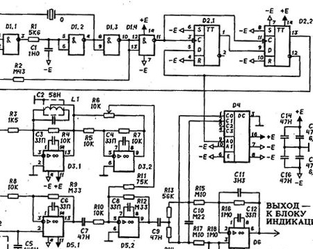
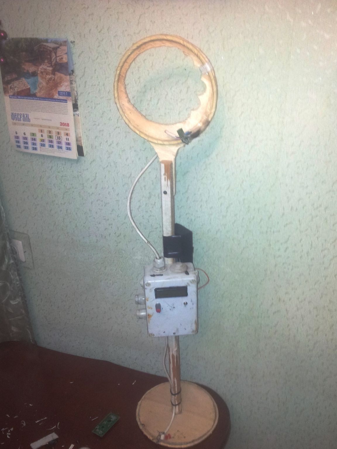
When I first started working with Arduino, I was so enthusiastic that I thought I could find and assemble any Metal Detector circuitry from the Internet on Arduino that I could easily find in the vast garbage dump. In principle, it turned out that way, but the circuits were based on a frequency counter, which did not allow achieving a really good range. Some children's toys and a test of the pen + attempts to make money on beginners. The original of this MD is a real workhorse that allows you to find large objects at a distance of 2m (see the Kolokolov-Shchedrin book in Google). There are no statistics on the transformed md. I hope she appears with the support of fans of MD and Arduino. The scheme worked with Arduino Uno and Arduino Pro Mini.

Further on the link is laid out the process of the birth of this MD on the website of the Soldering Iron, which lasted more than one year and pushed the author to study programming duin. Perhaps the sketch will seem wretched to someone - I will gladly accept your FIXES.


At the moment, there is a sketch that allows you to adjust the sensitivity barrier (pin 7 douins +1 to the barrier, pin 8 -1 to the barrier). .
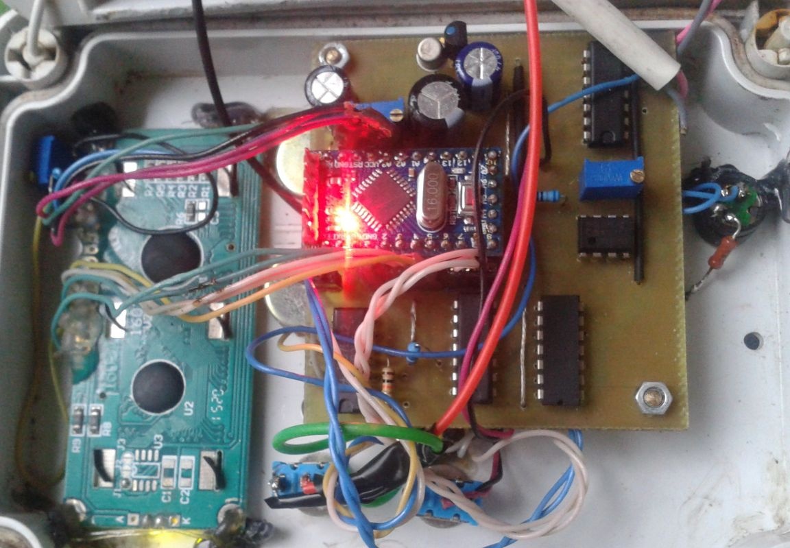
Arduino about mini 5v, 16MHz, ATmega168 and the display used these. Next to the scale is the Mini SD- adapter


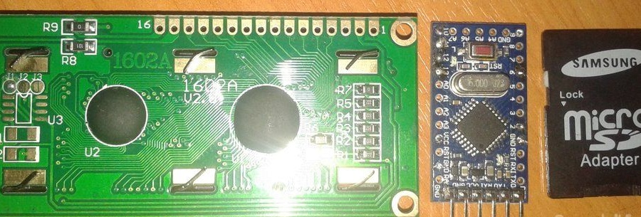
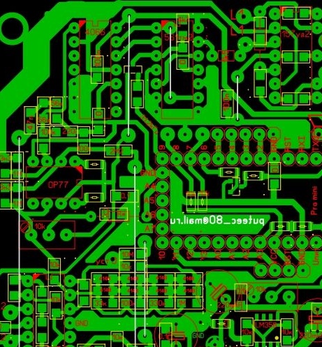
As already said 1602 costs 86 rubles, ProMini - 82 rubles. If you wish, you can generally take a naked ATmega168, develop a board for it and fill the sketch directly into it.And so, for example, I installed mom-dad on the MD board using the connector. The photo shows Arduino's 6-pin plug, through which sketches were poured directly on the board.

Sketch-MD.Rx-Tx.ProMini.SrednjajaTochkaRegBar.ino

// A3 analog input for voltmeter
// A4 analog input for signal
// 6- conclusion of the zook
// 9 - output frequency 31200 Hz
#include
Liquid Crystal lcd (12, 11, 5, 4, 3, 2);
                                       
  byte z1 [8] = {// battery icon
  0b01100, 0b11110, 0b11110, 0b11110, 0b11110, 0b11110, 0b11110};
 
 int countleds = 0; // variable to store the scale level value
 int voltag = 0; // variable to store the voltage value
 int noll = 0; // variable to store the midpoint value
   #define NUM_SAMPLES 10 // 10 analog samples to read in 1 second
   int sum = 0; // sum of samples taken
   int sun = 0; // same, but divided by 10
   unsigned char sample_count = 0; // current sample number with
   float voltage = 0.0; // calculated voltage
   const int button1 = 7; // barrier plus button
   const int button2 = 8; // barrier-minus button
   int i = 5; // barrier
   
void setup () {
     lcd.begin (16, 2); // display initialization
     lcd.setCursor (1, 0);
     lcd.setCursor (10, 1);
     lcd.print ("Rx-Tx");
     delay (3000);
     lcd.clear ();
     
     TCCR1A = TCCR1A & amp; 0xe0 | 2;
     TCCR1B = TCCR1B & amp; 0xe0 | 0x09;
     analogWrite (9, 126); // at pin 10 PWM = 50% f = 31200Hz
     
     lcd.createChar (1, z1);
     }
     
void loop () {
     int buttonState1 = HIGH; // The state of the button is one
     int buttonState2 = HIGH; // Two button state
   sample_count = 0; // reset the contour of the number of additions
   sum = 0; // reset the sum of 10 additions
   while (sample_count & lt; NUM_SAMPLES) {
   sum + = analogRead (A4); // the next measurement is added to the sum
   sample_count ++; // the unit is added to the measurement number
   sun = sum / 10;} // find the average value from 10 measurements
   
   noll = analogRead (A3) / 2; // midpoint power
   float voltage = map (analogRead (A3), 0,1023,0,1500) /100.0;
                                        // Voltmeter built at input A3
   if (sun & gt; = noll + i) {countleds = map (sun, noll + i, noll * 2 - 250, 9, 14);
                                        // if the received result is on the 9-15th segment of the scale
    tone (6, countleds * 100);}
   if (sun & lt; = noll - i) {countleds = map (sun, 116, noll - i, 0, 7);
                                        // if the resulting result is 0-7 segment of the scale
    tone (6, countleds * 50); }
     if (sun & lt; noll & amp; & amp; sun & gt; = noll - (i-1)) {countleds = 7;
    noTone (6); } // islet of virtual ZERO (7 segment)
     if (sun & gt; noll & amp; & amp; sun & lt; = noll + (i-1)) {countleds = 8;
    noTone (6); } // island of virtual ZERO scale (8 segment)

   
    {lcd.setCursor (countleds, 0); // set the cursor to the countleds column, line 0
    lcd.print ("\ xff"); // filled icon
    lcd.setCursor (0, 1); // move to 2 row, column-0
    lcd.print (char (1)); // Battery Icon Indication
    lcd.setCursor (1, 1); // move to voltage indication
    lcd.print (voltage); // voltage
    lcd.setCursor (7, 0); // 8th column 1st row
    if (sun & lt; noll) {lcd.print ("{");} // print
    lcd.setCursor (8, 0); // 9th column 1st row
    if (sun & gt; noll) {lcd.print ("}");} // print
    lcd.setCursor (7, 1);
    lcd.print ("B =");
    lcd.setCursor (9, 1); // 11 column 2nd row
    lcd.print (i); // barrier
    lcd.setCursor (13, 1); // 13th column 2nd row
    lcd.print (sun); // print the average value of the ADC value
    delay (100); // we wait
    
  buttonState1 = digitalRead (button1); // Read Button 1 Status
  buttonState2 = digitalRead (button2); // Read button 2 state
  if (buttonState1 == LOW) {i = i + 1; delay (50);}
                                        // When the button is pressed, the barrier grows by 1. Delay 50
  if (buttonState2 == LOW) {i = i - 1; delay (50);}
                                        // When the button is pressed, the barrier decreases by 1. Delay 50
  if (i & lt; 1) {i = 1;} // Lower boundary of the barrier
  if (i & gt; 38) {i = 38;} // The upper boundary of the barrier
 
 lcd.clear ();
    }
}

I didn’t use the car. The last two elements of TL074 were left idle. But on the circuit and board they are. You may want to bring them to working condition a little later. I believe that I have achieved my goal. The display unit works wonderfully. Everything else depends on the MD.
9.8
10
10

Add a comment

    • smilesmilesxaxaokdontknowyahoonea
      bossscratchfoolyesyes-yesaggressivesecret
      sorrydancedance2dance3pardonhelpdrinks
      stopfriendsgoodgoodgoodwhistleswoontongue
      smokeclappingcraydeclarederisivedon-t_mentiondownload
      heatirefullaugh1mdameetingmoskingnegative
      not_ipopcornpunishreadscarescaressearch
      tauntthank_youthisto_clueumnikacuteagree
      badbeeeblack_eyeblum3blushboastboredom
      censoredpleasantrysecret2threatenvictoryyusun_bespectacled
      shokrespektlolprevedwelcomekrutoyya_za
      ya_dobryihelperne_huliganne_othodifludbanclose
24 commentary
Author
Thanks puteec FU! I requested it from the second time. I stitched through Arduino uno. The problem disappeared after updating the bootloader. Now interests how to configure further.
puteec fu
Any Arduino is suitable for atmega168, atmega328. About nano it with usb connector if not mistaken. Sew in the Arduino ide from the examples of the Blink sketch (blinking LEDs on pin 13, the LED is installed on the board). Make sure that you are using the correct port, the board is selected correctly, the processor on the board is selected correctly, the quartz frequency on the board is selected correctly, the firmware method (μ2) is selected correctly.
Error not encountered.
Create a new file in Arduino, copy the sketch from here to a new and clean sketch and it will work.But first, make the LED on the Arduino board blink with a standard flashing example. Then move on.
I bought Arduino p nano only on the Atmega328 processor. I reviewed a bunch of videos and forums ... they said that it should come up .... but then the bummer is NOT flashing .... gives #include expects "FILENAME" or . Has anyone encountered this?
Author
A sketch works with this board. What exactly is the plug formed?
If you pour the last sketch, then all the details related to D3.3 and D3.4 as well as they themselves can not be installed. On the soldering iron there is a redrawing on this topic
Anjey888
Hello. This topic is very interested. I want to assemble the device. I made a soldering iron board off the go ... and then got stuck. Since there is a lot of disagreement between the board and the circuit. Started comparing your board ... that's a big difference. But confused with the harness at Arduino.
I ask the help of knowledgeable people.
Author
The same as for other metals. Depth of detection depends on the area of ​​the target. The more, the deeper.
Guest Eugene
What are the limits for detecting objects? Gold, aluminum, copper.
Guest Alexander
What to do now, because there is still a Schottky barrier?
Author
Here you go! About even the smallest value is out of the question! Thank you for the explanation.
Quote: puteec_80
And people will more quickly and intuitively understand what I’m talking about.
You can continue to remain in this error. ((Technically literate people will be at a slight loss.
BARRIER, husband.
1. An obstacle (a kind of wall, a crossbeam) set in the way.
2. Fence, fencing.

THRESHOLD, threshold, husband.
1. In science and technology, the threshold is called the smallest value, the degree of manifestation of something.
The sensitivity threshold of the device. | Hearing threshold. | Threshold of pain. | The sensor is triggered when the set temperature threshold is exceeded.
smile
Author
Let's stay with our own. I will write "increasing the barrier by one unit" and "the sensitivity of the receiver was 5 μV." And you write “Increasing the threshold of operation by one unit” and “the threshold of sensitivity of the receiver ..” Moreover, people will more quickly and intuitively understand what I’m talking about.
And I explain in this example. There is no threshold strictly speaking, because there is no clear reference scale. There is some kind of cutout floating band from a floating signal. So, it seems to me that the definition of a barrier is much more suitable for this “floating” strip than for a threshold.
Generally pointless and stupid argument. Do you have any questions?
Quote: puteec_80
What are their lower and upper thresholds?
Maybe the meanings of the translated words do not match or slightly do not match. But they perfectly describe the process and gradually enter into slang.
Exactly what the threshold is. The response threshold is in your case. Please explain how the “barrier” describes the process.
As for joining slang - now there are a lot of all kinds of misunderstandings there. ((
Author
In this case, I still tend to use the word "barrier", because it is the barrier that is set in the text of the program, just not falling into its range, the signal is perceived by the microcontroller as useful. And it’s the barrier because It has two values ​​- the upper and lower limits of the run-in i.e. operation occurs above the "upper" and below the "lower" border of the barrier on the ADC scale. However, you know better. What are their lower and upper thresholds?
Maybe the meanings of the translated words do not match or slightly do not match. But they perfectly describe the process and gradually enter into slang.
By the way. Sensitivity and the barrier are completely different things.
Yes.They intersect. But not more.
Quote: puteec_80
In foreign MD, the menu says "Barier".

I may surprise you, but many English words that look similar to ours have a different meaning, sometimes close, sometimes not. Search for the words "false translator friends."
Now essentially. In Russian technical documentation not there is simply no such phrase “barrier of sensitivity” - and that’s it! There is a “threshold of sensitivity”, in some cases one can say a “limit of sensitivity”, but not a “barrier of sensitivity”. Perhaps in some other branches of knowledge it is used, but not in electronics.
Author
Well, it means that all foreign engineers are jumping over a stick on the road. In foreign MD, the menu says "Barier". Comrade Ivan, you are falling in my eyes with such petty quibbles! Where are your comments on the merits? After which you have to clap your hands flat on the forehead? You used to spoil me often punish
The difference is significant: the threshold is a technical term, the barrier is a "stick across the road."
Author
Can. But I do not see the difference.
Maybe not a "barrier", but a threshold? ;)
Author
The diagram does not show the barrier adjustment buttons. They are connected to pins 7 and 8 of the Arduino. Each pulled up with a resistance of 10k to the plus, closes when you press the mass.
Author
void loop () {
int buttonState1 = HIGH; // The state of the button is one
int buttonState2 = HIGH; // Two button state

int pot = analogRead (A4); // filter for fast signal change
sign = sign * (1-K) + pot * K;

noll = noll * (1-L) + sign * L; // long-term signal filter
// Voltmeter built at input A3
float voltage = map (analogRead (A3), 0,1023,0,1500) /100.0;

if (sign> = noll + i) {countleds = map (sign, noll + i, 1023, 9, 14);
// if the received result is on the 9-15th segment of the scale
tone (6, countleds * 100);}
if (sign <= noll - i) {countleds = map (sign, 0, noll - i, 0, 7);
// if the resulting result is 0-7 segment of the scale
tone (6, countleds * 50); }
if (sign = noll - (i-1)) {countleds = 7;
noTone (6); } // islet of virtual ZERO (7 segment)
if (sign> noll && sign <= noll + (i-1)) {countleds = 8;
noTone (6); } // island of virtual ZERO scale (8 segment)


{lcd.setCursor (countleds, 0); // set the cursor to the countleds column, line 0
lcd.print ("\ xff"); // filled icon
lcd.setCursor (0, 1); // move to 2 row, column-0
lcd.print (char (1)); // Battery Icon Indication
lcd.setCursor (1, 1); // move to voltage indication
lcd.print (voltage); // voltage
lcd.setCursor (7, 0); // 8th column 1st row
if (sign lcd.setCursor (8, 0); // 9th column 1st row
if (sign> noll) {lcd.print ("}");} // print
lcd.setCursor (7, 1);
lcd.print ("B =");
lcd.setCursor (9, 1); // 11 column 2nd row
lcd.print (i); // barrier
lcd.setCursor (13, 1); // 13th column 2nd row
lcd.print (sign); // print the average value of the ADC value
delay (10); // we wait

buttonState1 = digitalRead (button1); // Read Button 1 Status
buttonState2 = digitalRead (button2); // Read button 2 state
if (buttonState1 == LOW) {i = i + 1; delay (50);}
// When the button is pressed, the barrier grows by 1. Delay 50
if (buttonState2 == LOW) {i = i - 1; delay (50);}
// When the button is pressed, the barrier decreases by 1. Delay 50
if (i <1) {i = 1;} // Lower boundary of the barrier
if (i> 38) {i = 38;} // The upper boundary of the barrier

lcd.clear ();
}
}
Author
New sketch. The algorithm for detecting the useful signal has been changed. The scheme is simplified, there are no elements D3.4 and D3.3 with all their bindings. If you take your own signet, then all these details can simply not be installed. More sensitivity. No false positives.
Sketch:

// A3-analog input for a voltmeter. Settable by potentiometer R32.
// A4-analog input for the signal. Set with the minimum signal on D3.2
// resistor R40 for the ADC readings of about 510.
// 6- conclusion of the zook
// 9 - output frequency 31200 Hz
#include
Liquid Crystal lcd (12, 11, 5, 4, 3, 2);

byte z1 [8] = {// battery icon
0b01100, 0b11110, 0b11110, 0b11110, 0b11110, 0b11110, 0b11110};
int countleds = 0; // variable to store the scale level value

float voltage = 0.0; // calculated voltage
const int button1 = 7; // barrier plus button
const int button2 = 8; // barrier-minus button
int i = 5; // barrier
const float K = 0.1; // filter tracking fast changes (coefficient. the smaller the stronger)
const float L = 0.07; // filter tracking changes over a long time
float sign = 0; // filter
float noll = 0;

void setup () {
lcd.begin (16, 2); // display initialization
lcd.createChar (1, z1);
pinMode (9, OUTPUT);
pinMode (6, OUTPUT);
TCCR1A = TCCR1A & 0xe0 | 2;
TCCR1B = TCCR1B & 0xe0 | 0x09;
analogWrite (9, 126); // at pin 10 PWM = 50% f = 31200Hz
// in fact, for PWM = 50% you need to set at least 220 filling, according to the oscilloscope
// the duin can't handle it. This is not critical.
}
Author
Those who will watch the sketch. The signs> = and <= have been replaced by strange combinations of & gt and & lt. Why dont know. When debugging was normal.

We advise you to read:

Hand it for the smartphone ...