
Good day to all dear friends! In today's article, I would like to show you a very interesting idea about homemade. I think many people have heard, know or already made automatic locks with wireless control, such locks can be made thanks to various modern Chinese wi-fi, bluetooth and infrared control modules, you can also make such a device using a conventional radio control, there is a huge amount on Aliexpress website such modules, even with built-in relays, which is unrealistically convenient. Well, then, in today's article we will focus on such a castle do it yourself, which will be controlled with a small remote control, it’s very easy to make such a lock, here you don’t even need to solder anything, I think this electronic many will appreciate the castle, but we will not pull it. Let's go!
And so, for a wireless electronic lock, we need:
-Two 9V crown batteries
Battery Connectors
small plywood slice
gear motor from China
the usual medical syringe
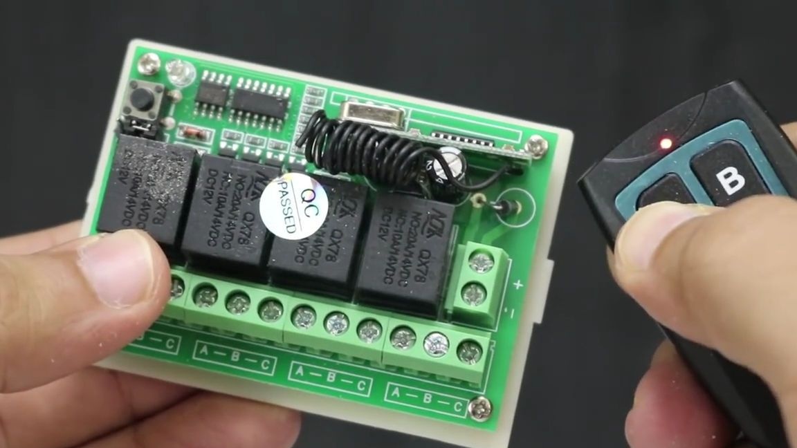
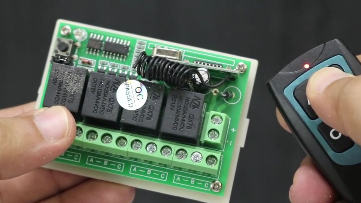
- a remote relay for 2 or 4 channels with a control panel (you can also order from China if there is none, it costs around 200-500 rubles, you can find a module with one relay and its price will be much lower, I even wrote an article on similar module for this site)
- wires in rubber or silicone insulation
metal nut
long bolt under the nut
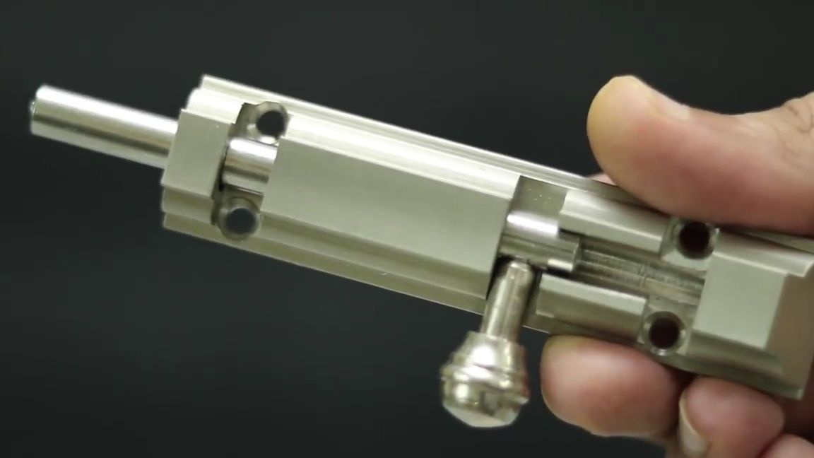
-door latch
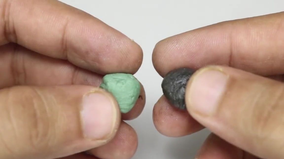
- self-hardening plastic for needlework (there are many types, you can buy in China, but it is also worth looking in your city for shops for needlework)
Of the tools we will also need:
thermal glue
-screwdriver
-stationery knife
soldering iron
pencil or marker
- mini drill or screwdriver
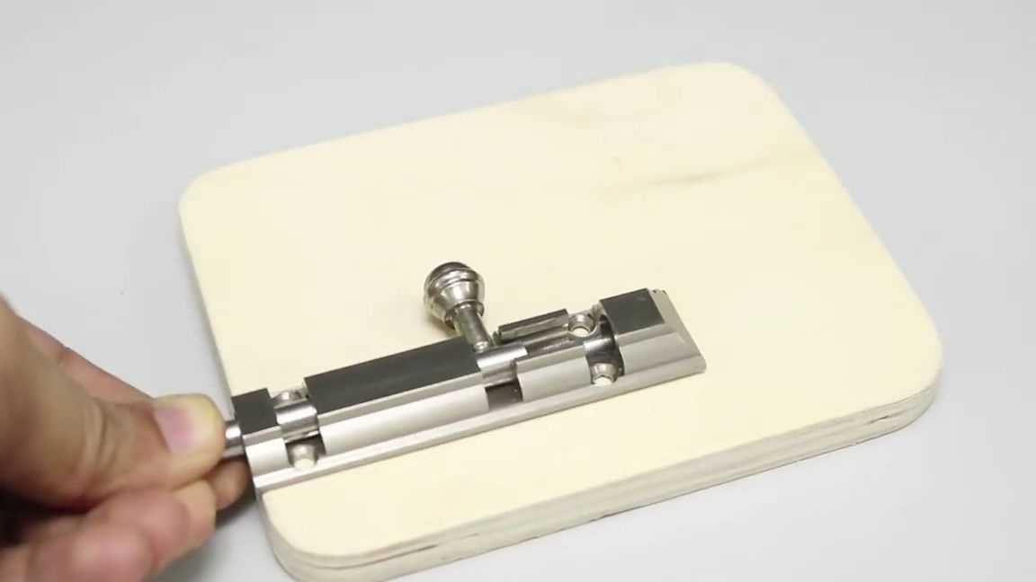
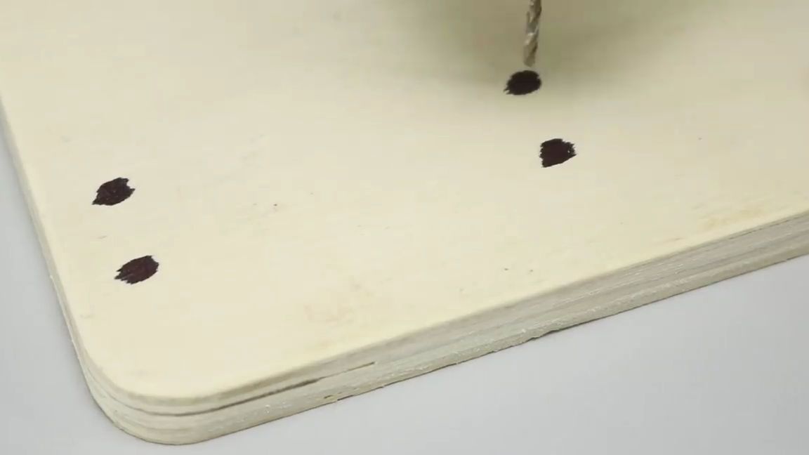
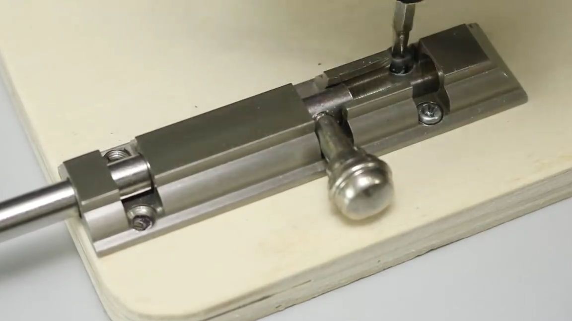
First of all, you need to cut out the base for our castle from plywood, make the size convenient for you, but so that all the electronics can fit on it. Then we take the “latch”, apply it to the plywood blank and mark it with a pencil or marker for the place where the “latch” is fastened:
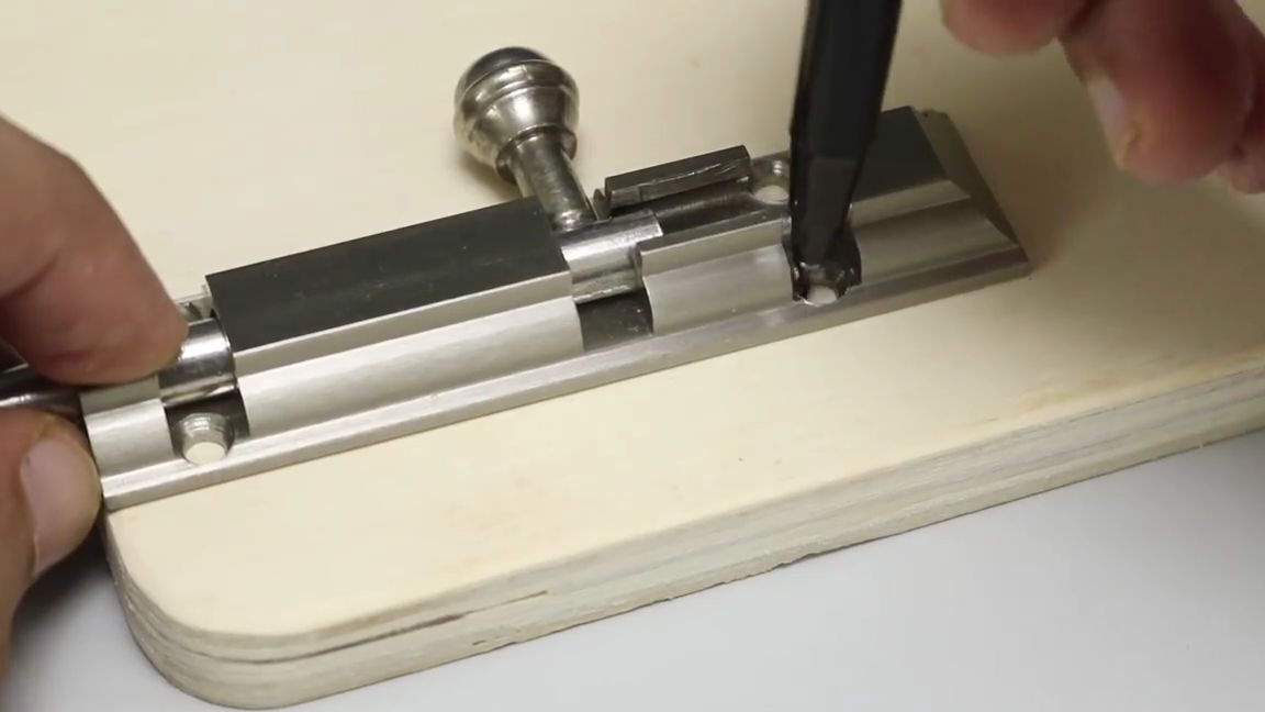
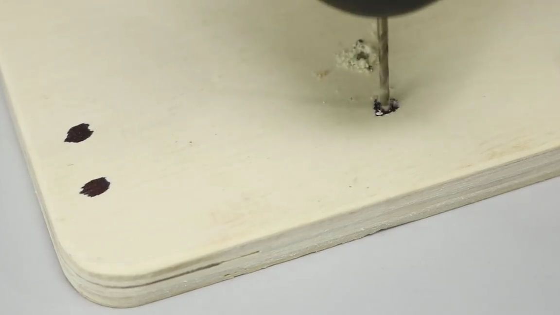
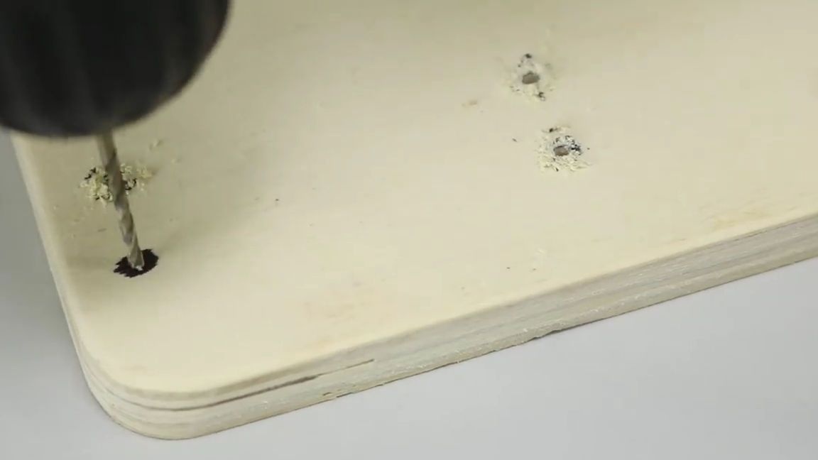
With a drill or a screwdriver, we drill holes in the previously marked places, the drill should be under the screws or screws that you are going to use:
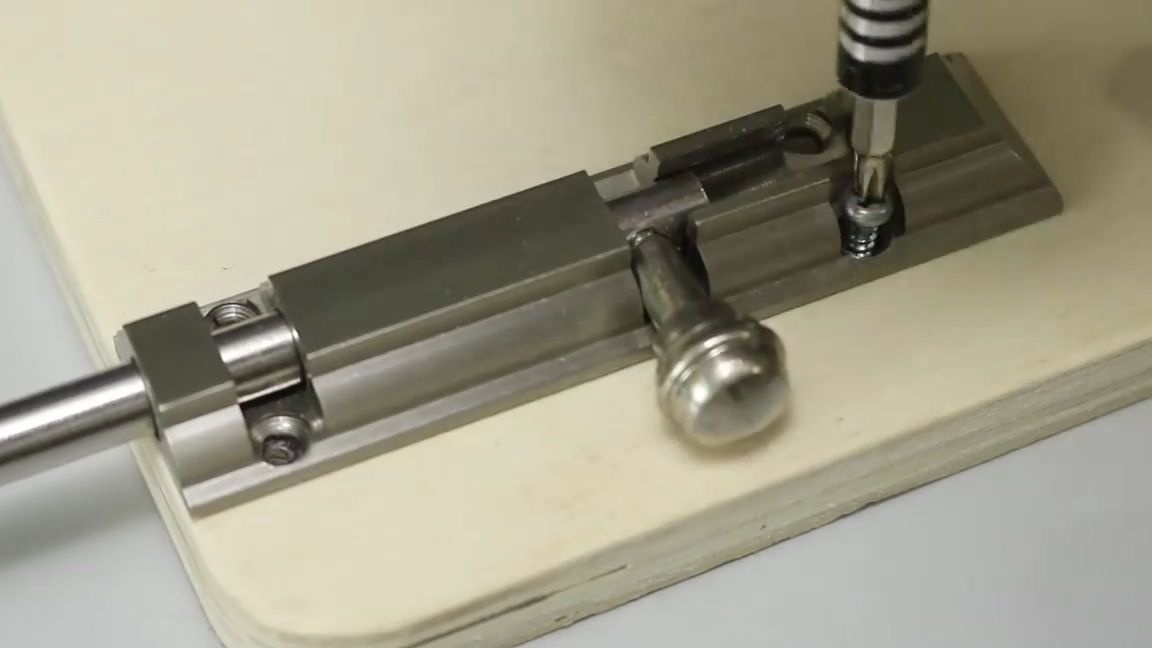
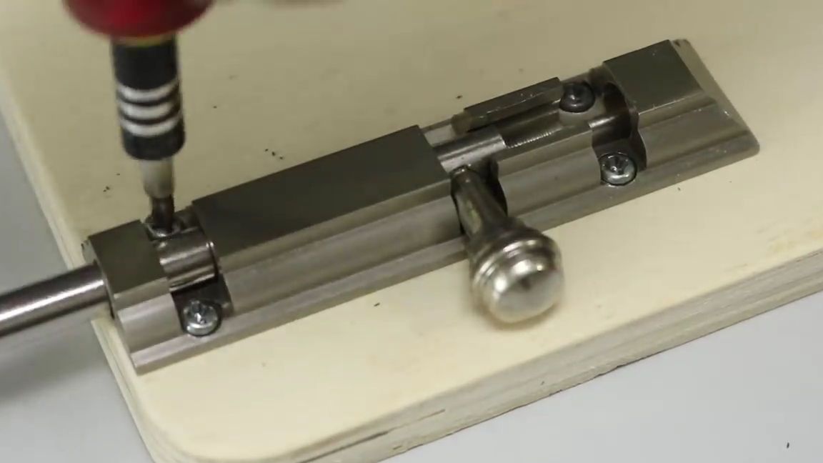
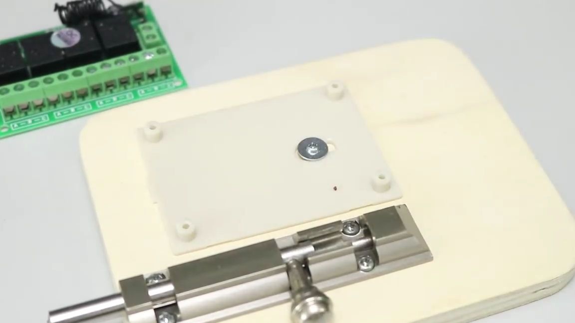
Then we fasten the “latch” to the plywood, as shown in the photo below:
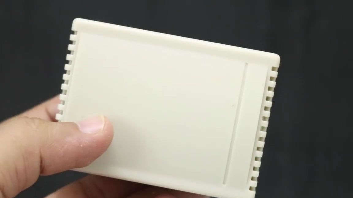
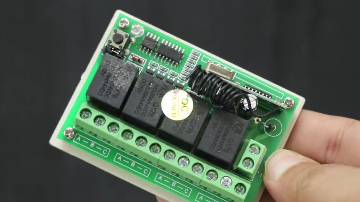
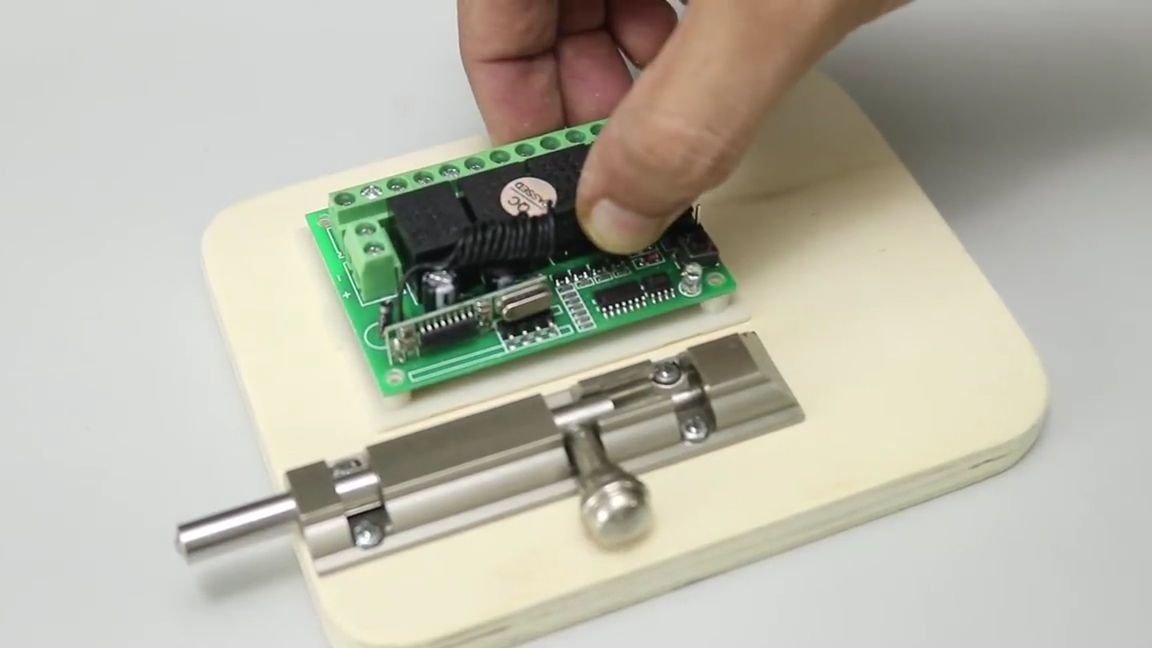
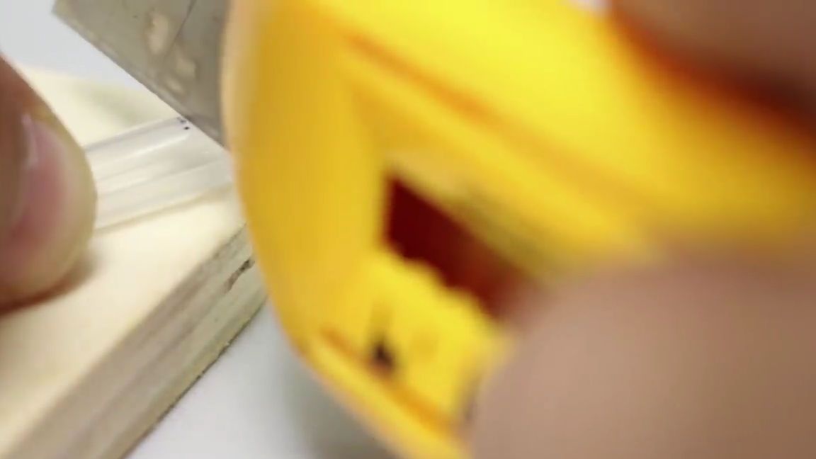
We take our module for wireless control of the relay and remove it from its original box (if the box for use did not come with your relay, then do it yourself, to your taste and color), and then check for operability:
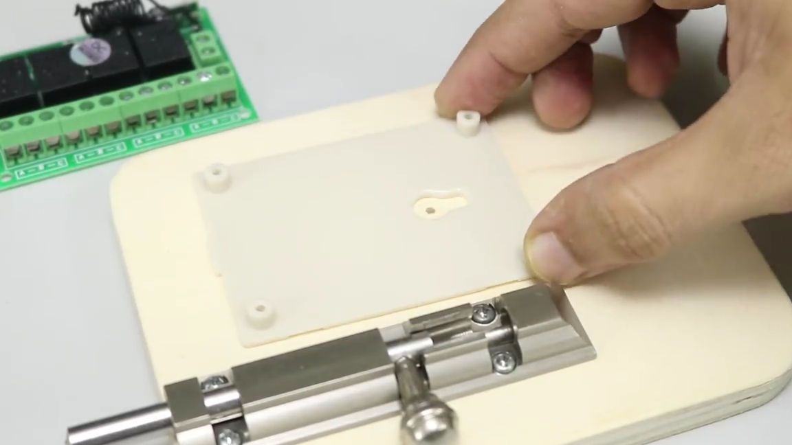
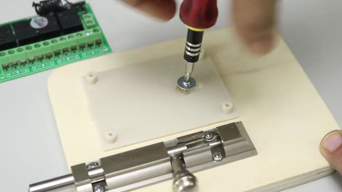
We fasten the lower part of the box to the plywood blank as follows:
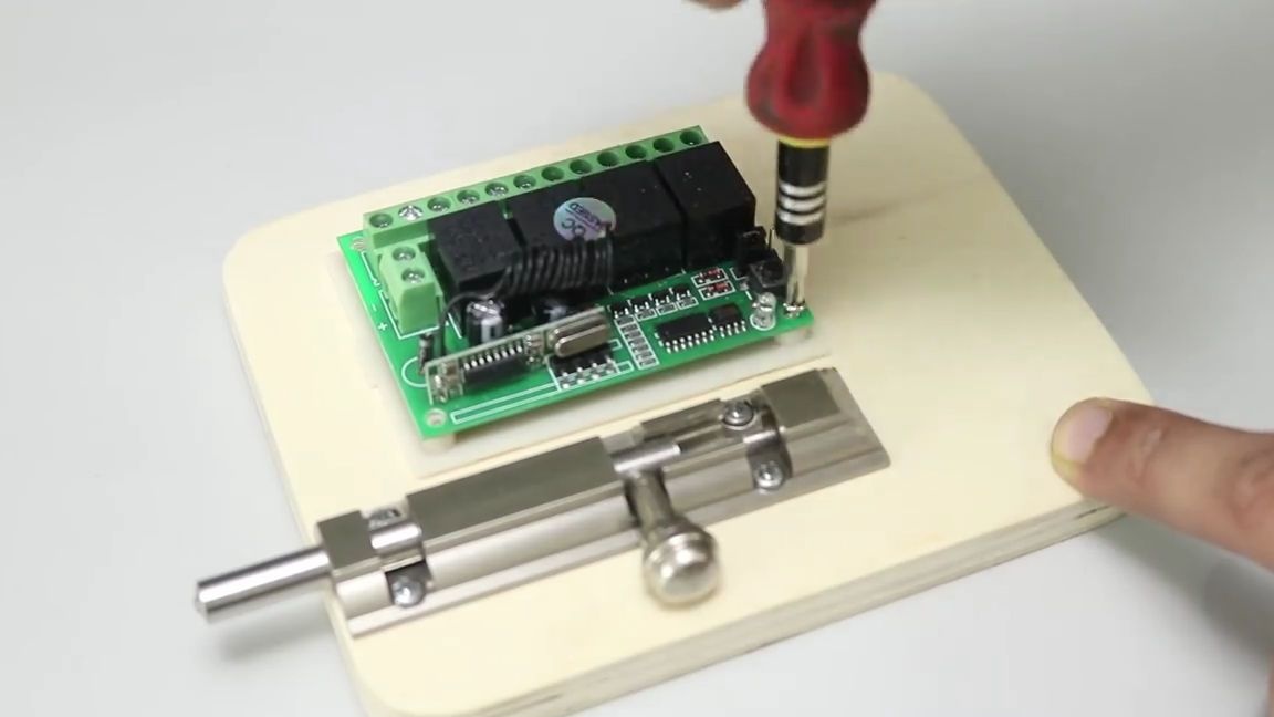
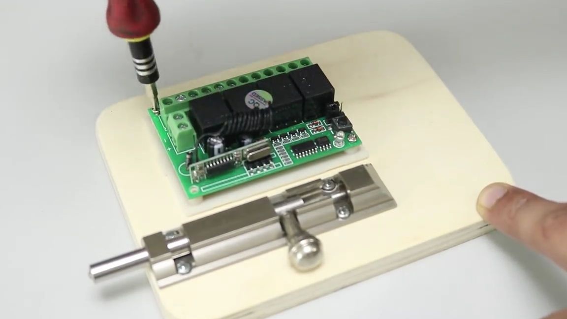
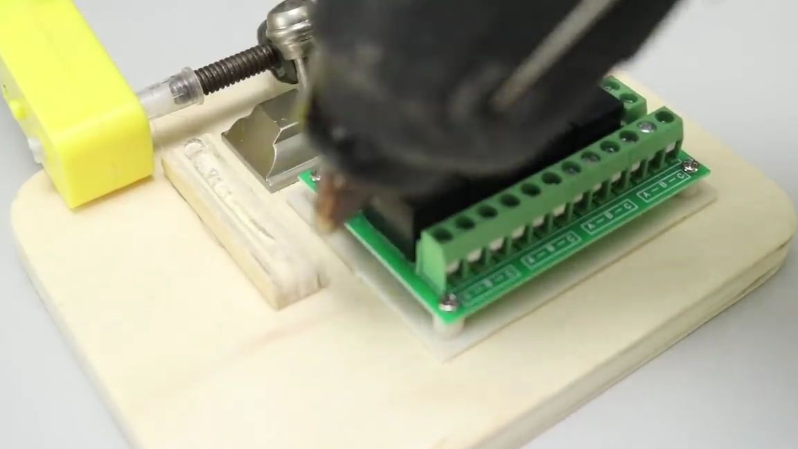
We install the relay on the “legs” intended for it and also fasten it with screws and a screwdriver:
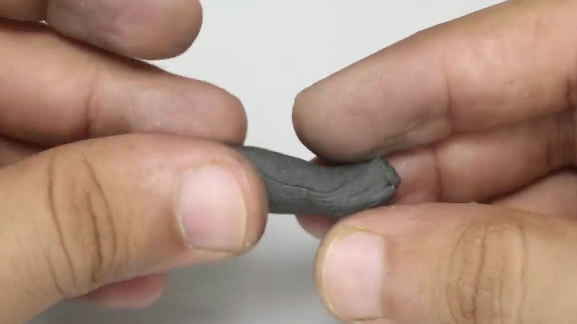
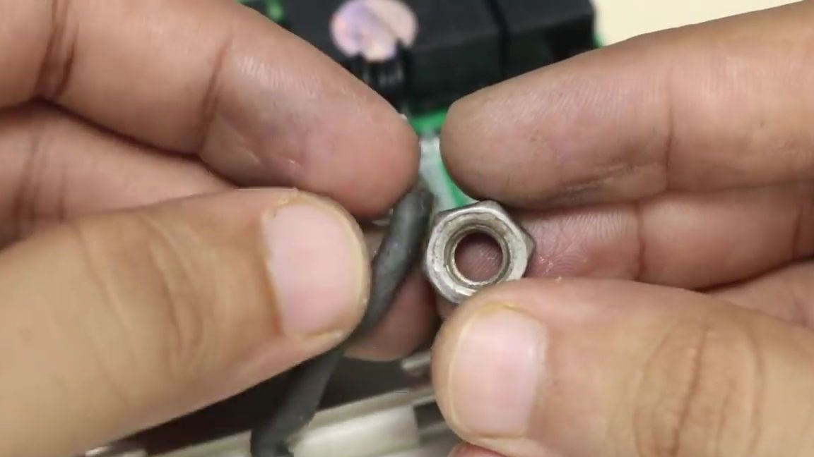
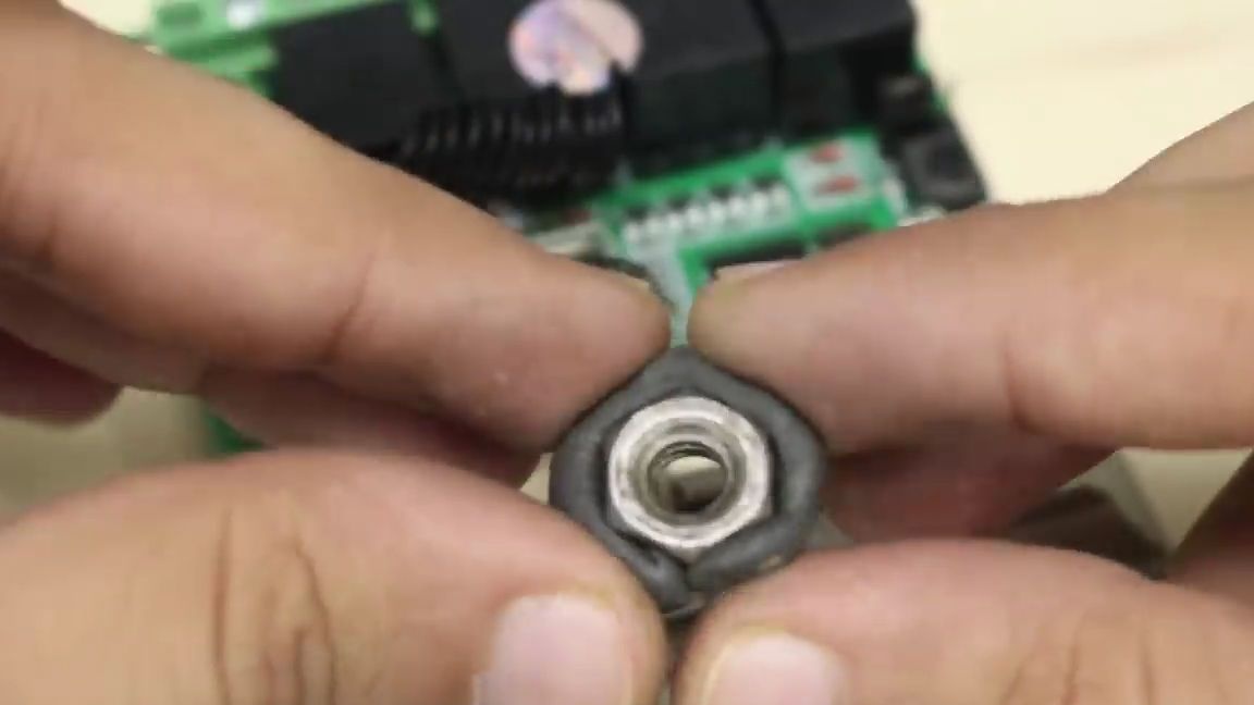
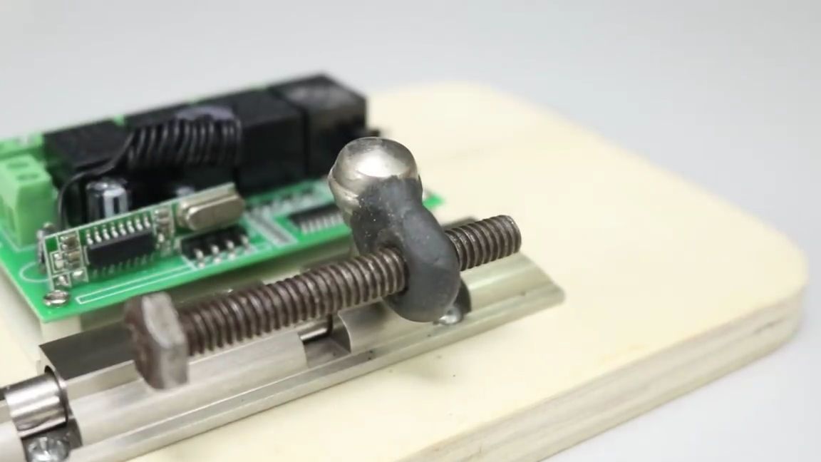
We take self-hardening plastic, which by the way is very similar to plasticine and in its initial form is very similar in properties to it, thanks to this it can be turned into almost any form using only my hands, which is very convenient. Following the instructions of your plastic, we form a small ring and apply it to the nut, as shown in the photo:

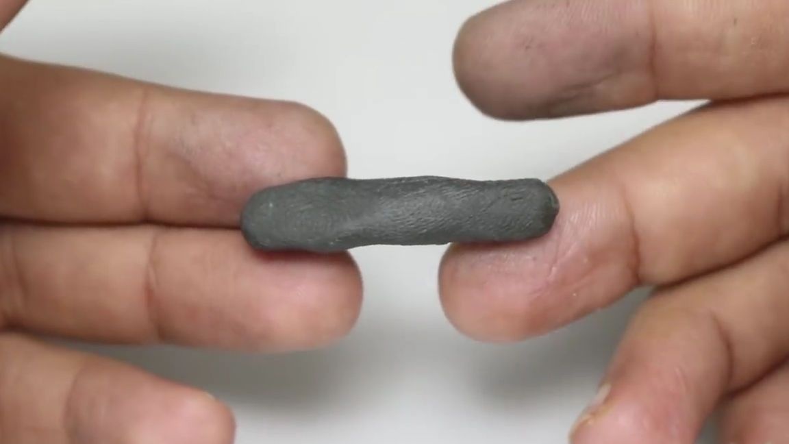
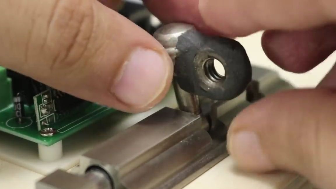
Then we glue it to the handle of the “latch” with the same self-hardening plastic as shown in the photo, and wait for the required amount of time until the plastic hardens:
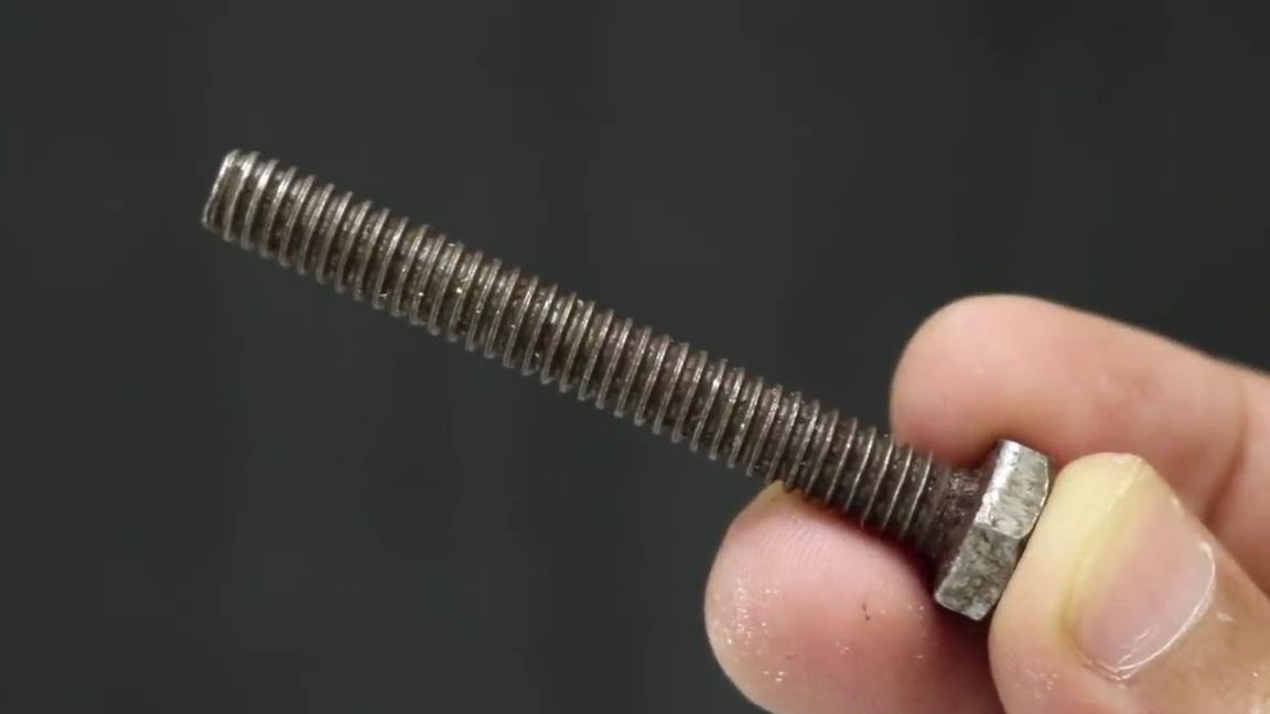
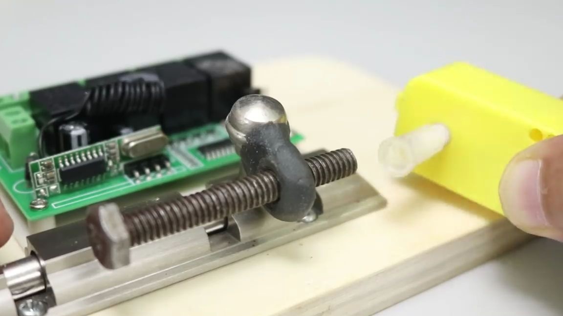
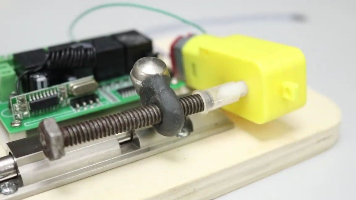
Take a long bolt under the nut and screw it into our billet, about a third:
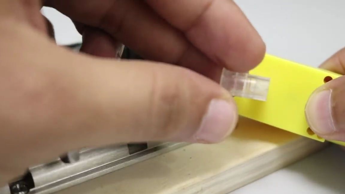
We take an ordinary medical syringe and remove the protective cap from it, we only need it:
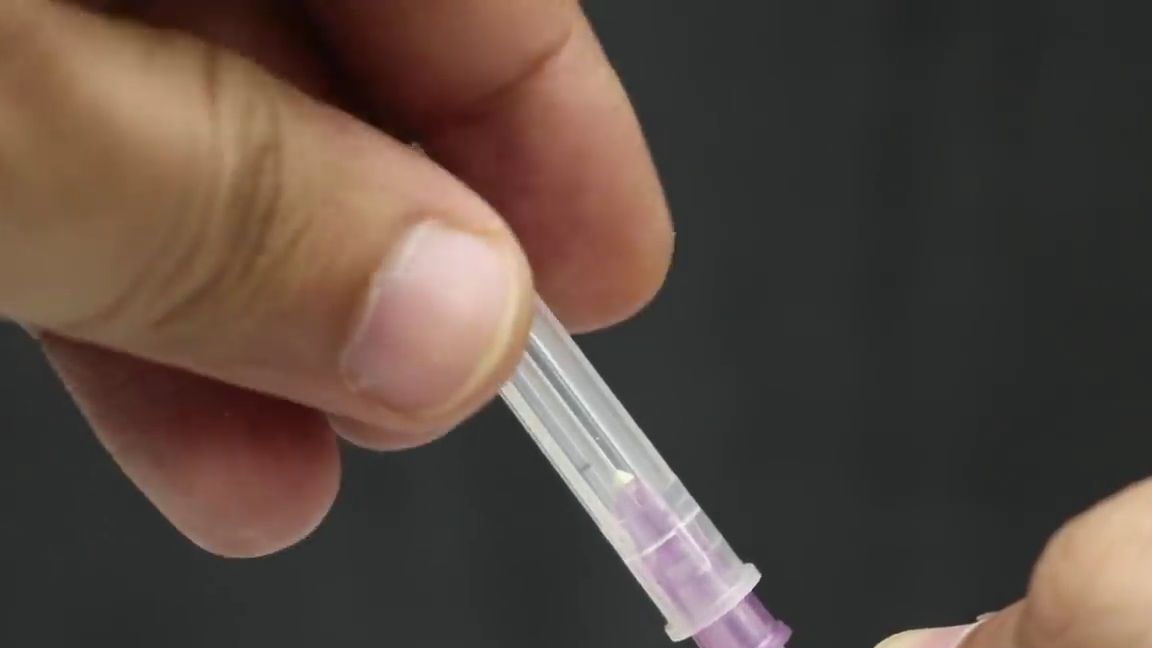
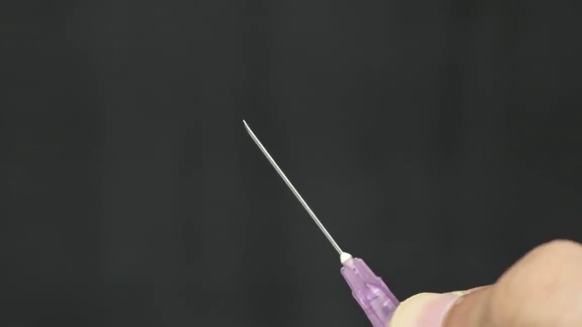
From the cap using a clerical knife, cut a small piece from its beginning:
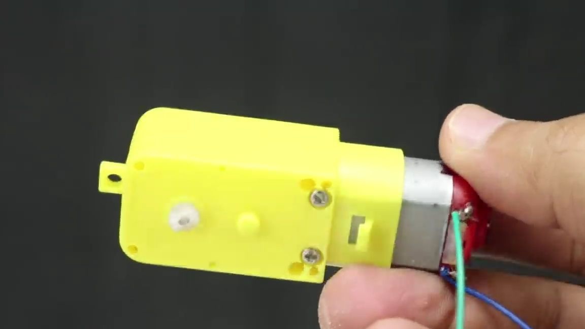
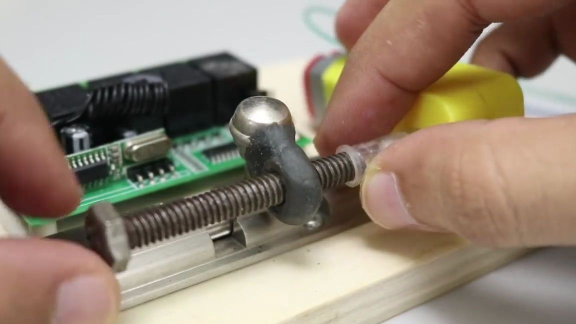
Now you need to take the gear motor (by the way, I myself often use it in my homemade products, and other homemade authors also like to use them, so I advise you to order a couple for yourself, besides they cost only around 60 rubles) and solder to his cantacts a pair of wires, preferably of a different color, in order to prevent mistakes when connecting:
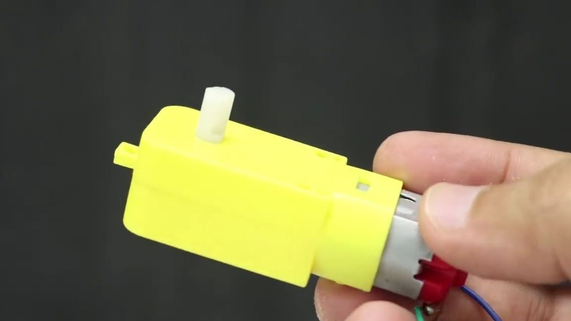
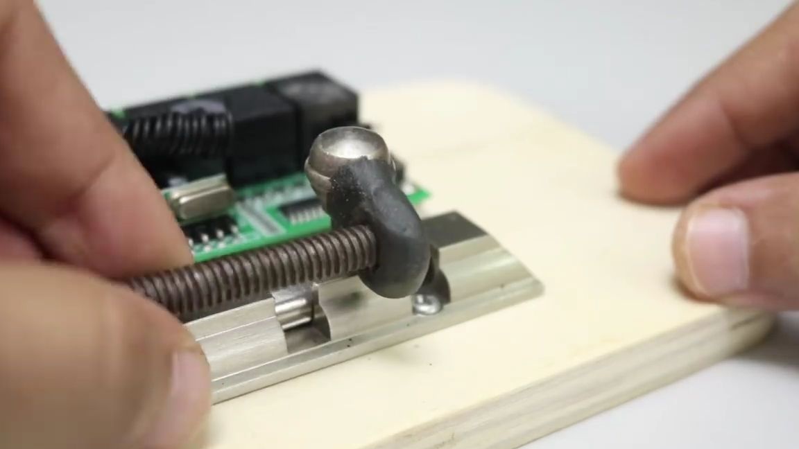
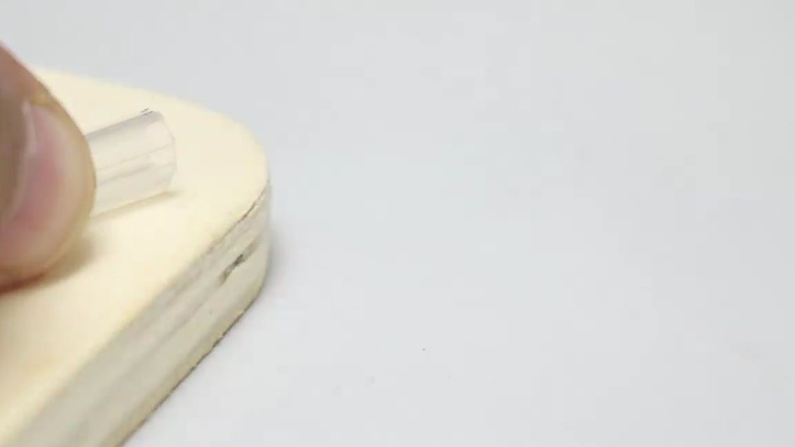
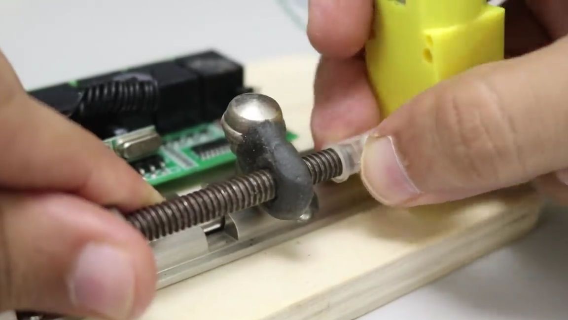
Glue the segment from the cap of the syringe to the axis of the motor, and put the remaining half on the bolt as shown in the photo:
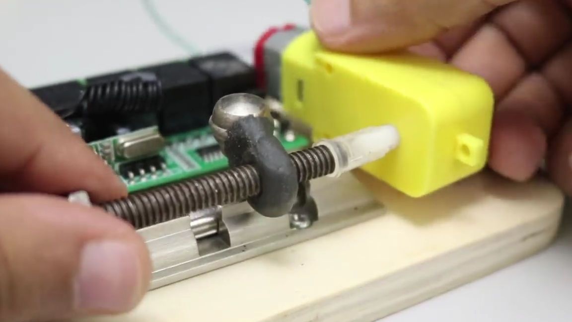
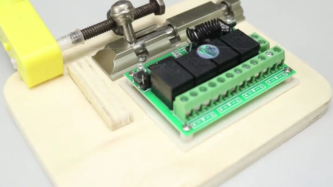
On the plywood, next to the gearbox, apply a little thermal glue and
glue a small wooden block on it:
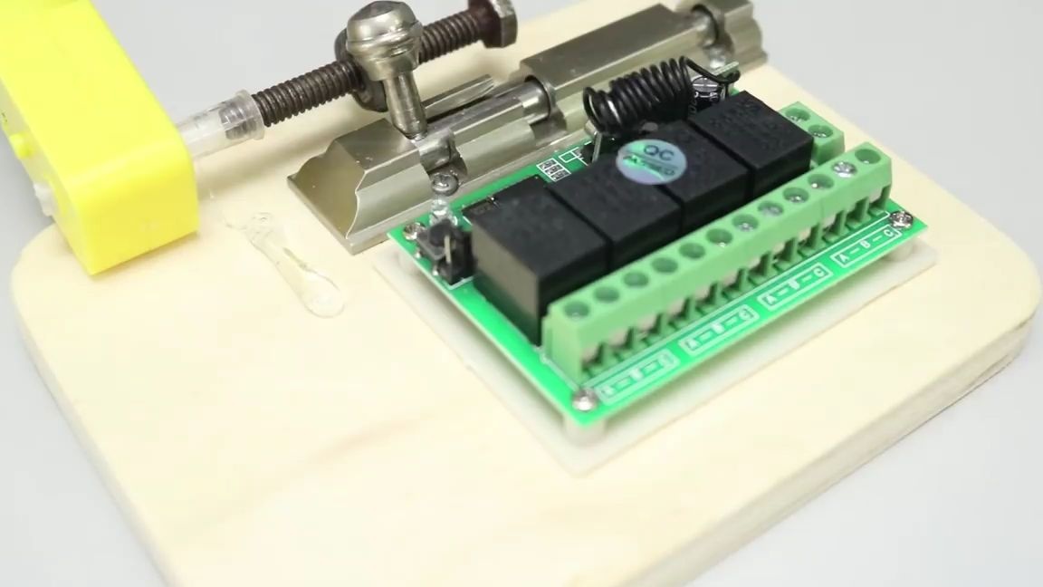
We also apply a little thermal glue to the bar and glue the gear motor itself to it:
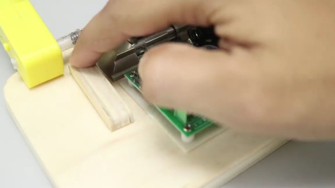
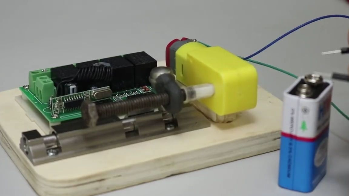
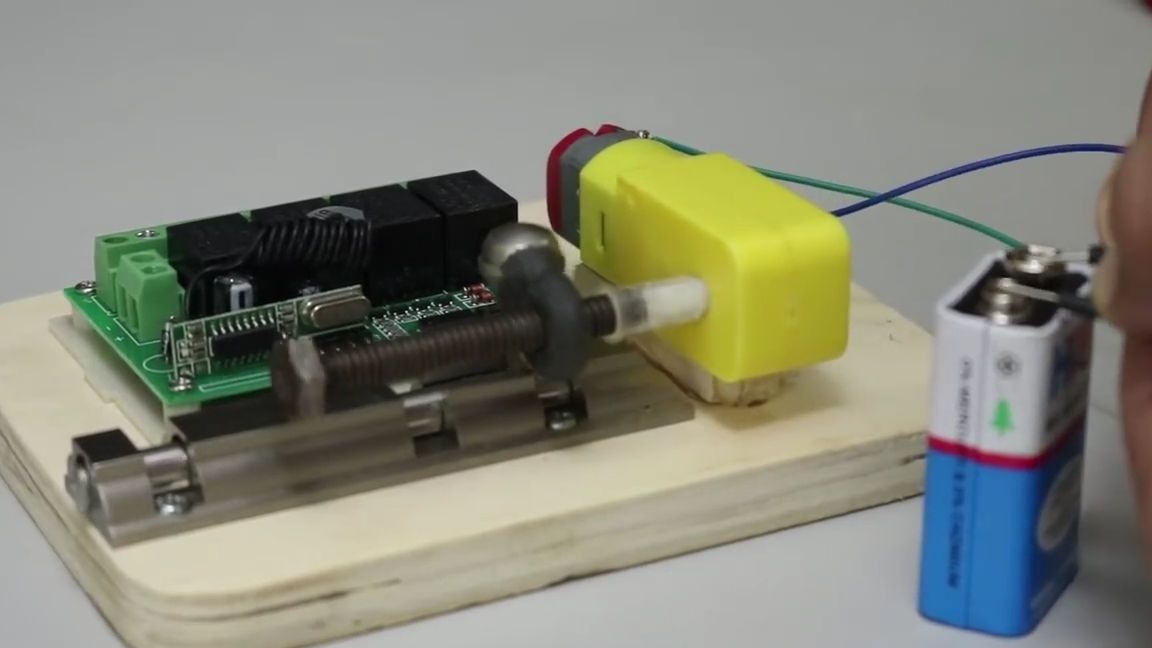
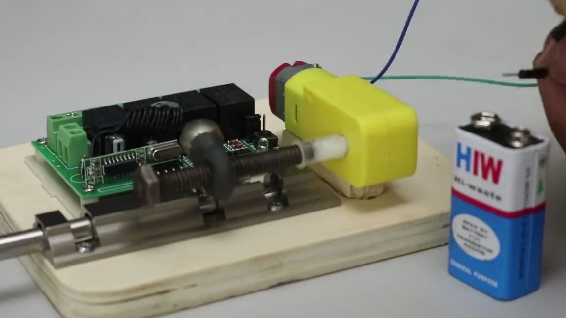
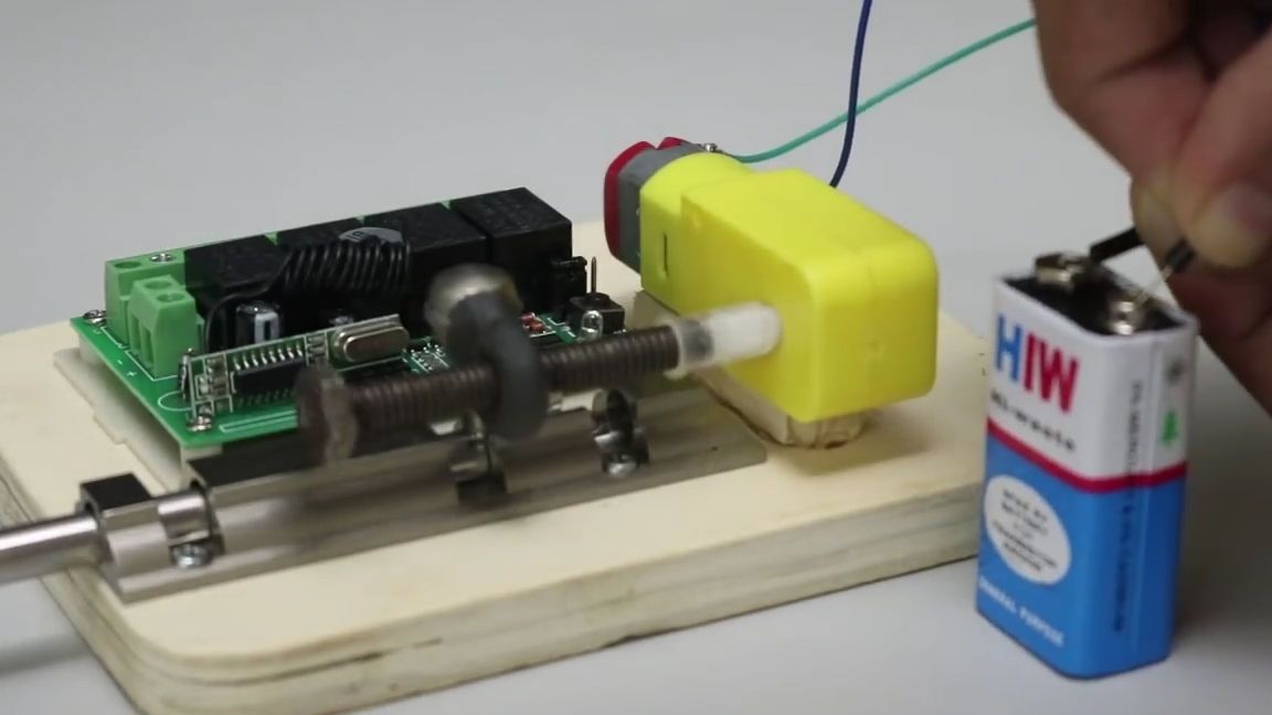
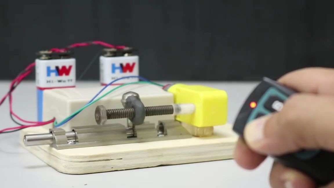
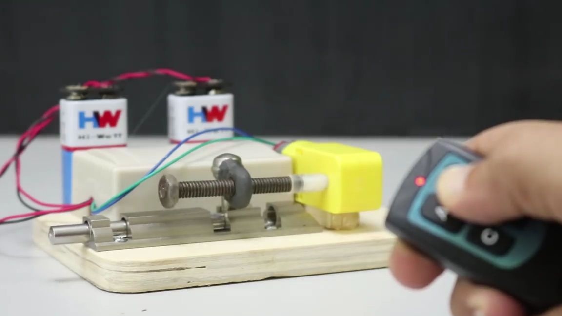
Testing our mechanism to open the "latch".
We connect the gear motor to the power source, which in our case is a 9-volt crown, after connecting the motor starts to rotate the bolt around its axis, thereby unscrewing it from the nut, but since the bolt is in a horizontal plane in a stationary state, the nut begins to move in the opposite direction of twisting and because of this the “latch” move forward. If you change the cantacts in some places (by changing this polarity) the motor will start moving in the opposite direction and the “latch” will begin to move back.
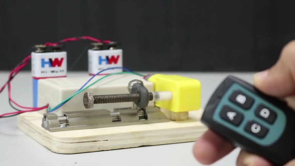
If you did everything correctly and everything works for you, then you can continue the assembly:
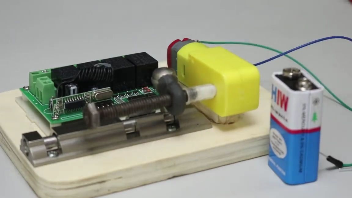
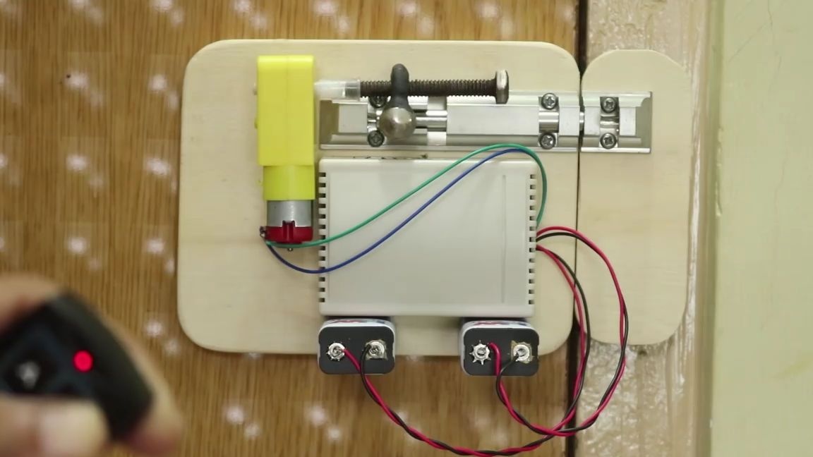
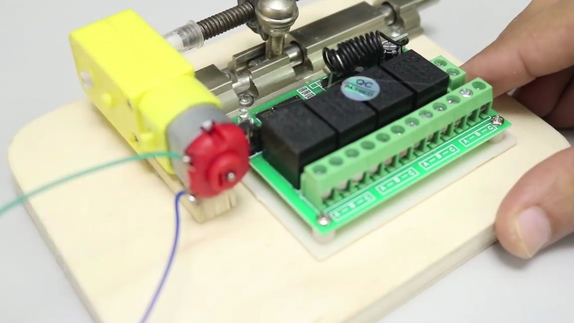
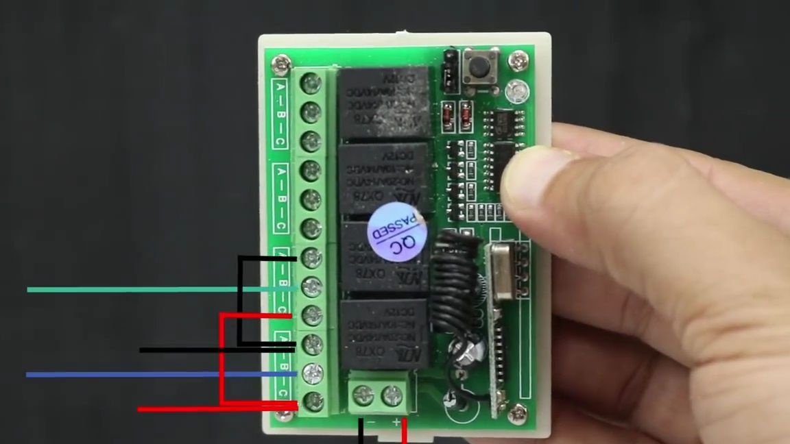
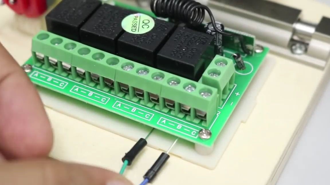
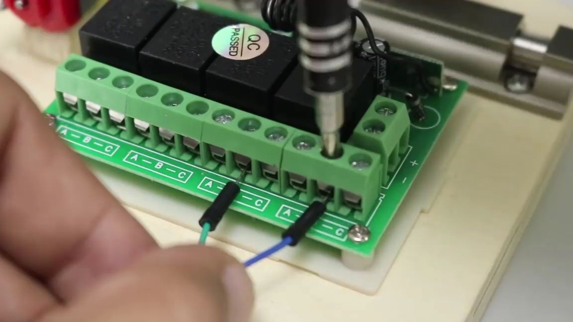
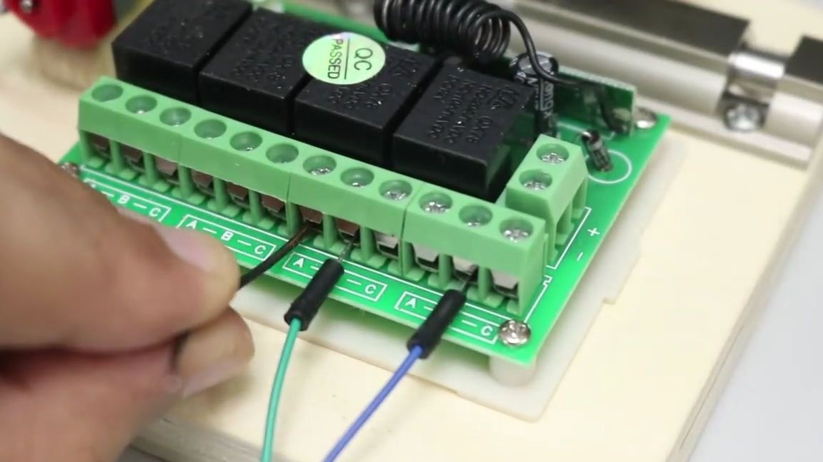
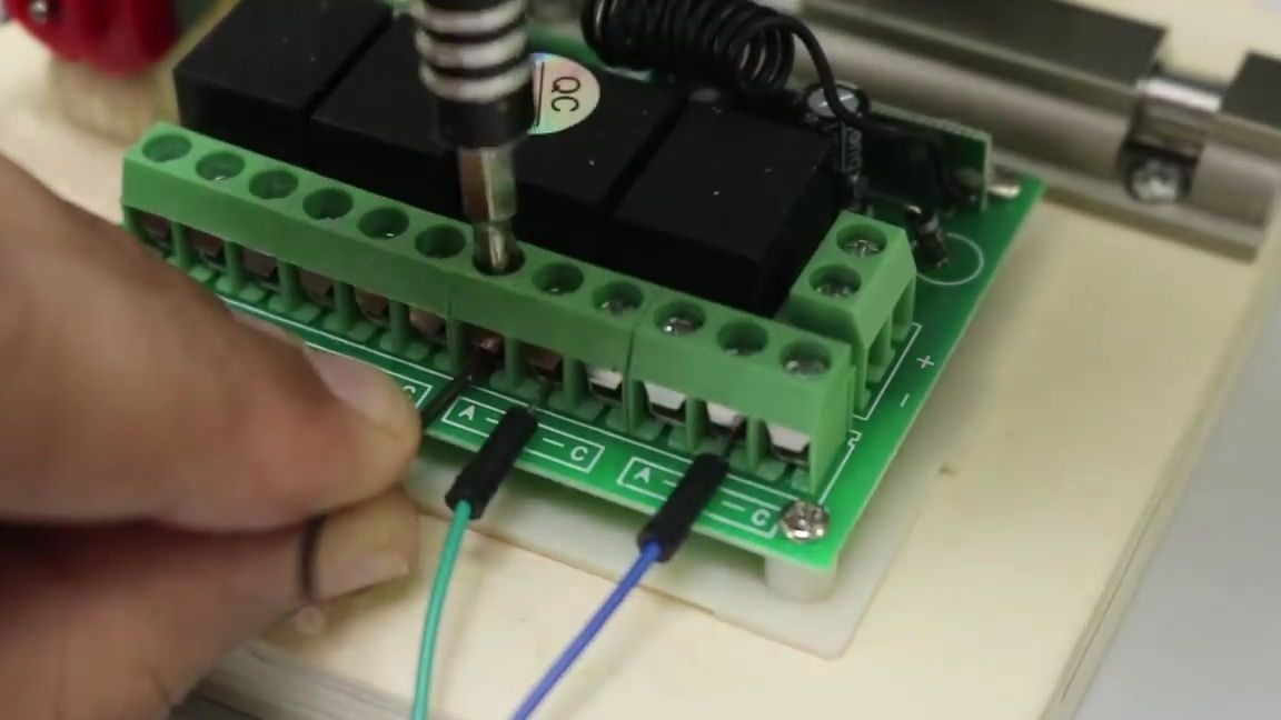
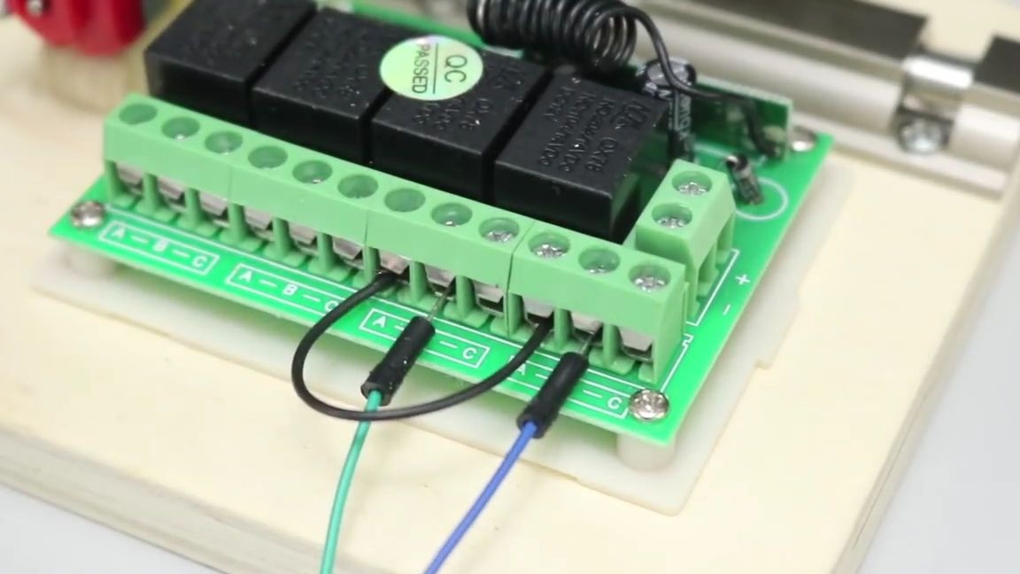
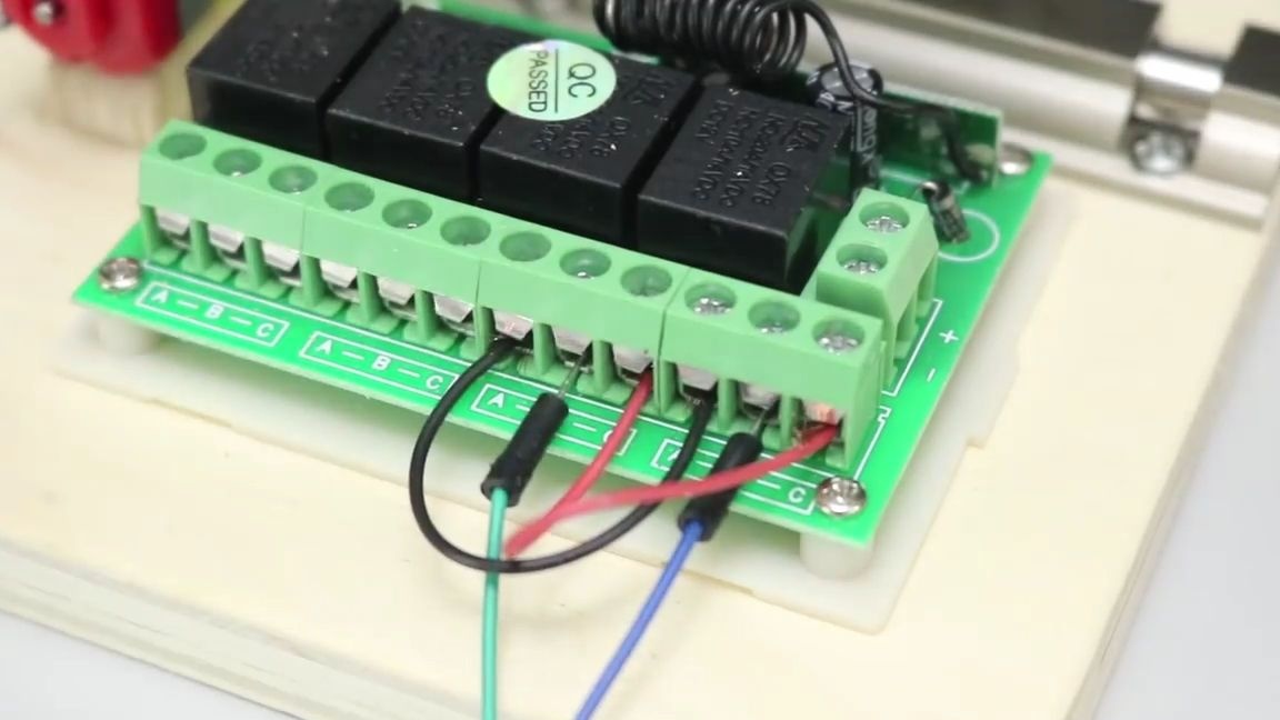
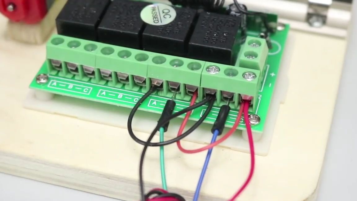
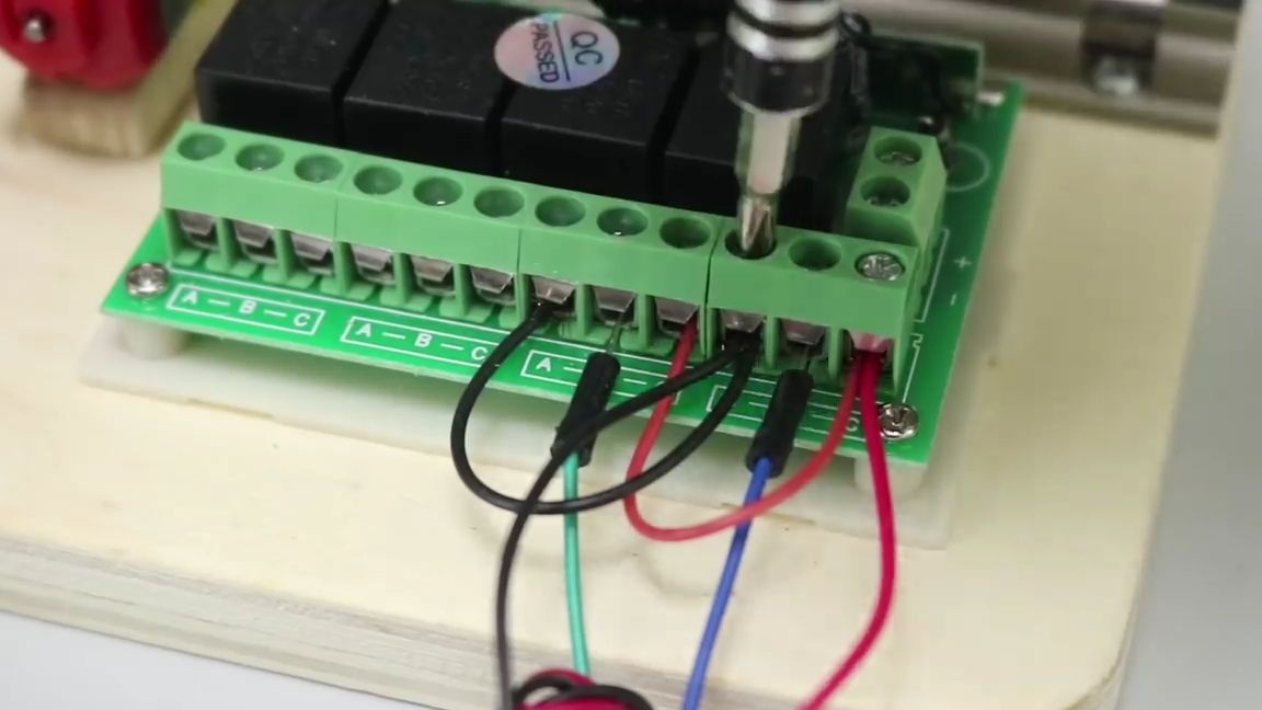
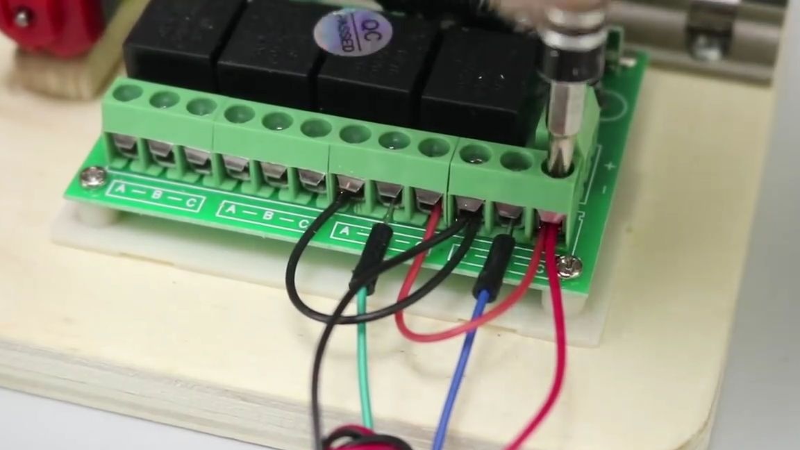
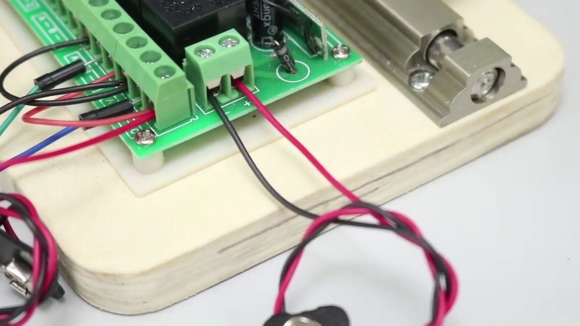
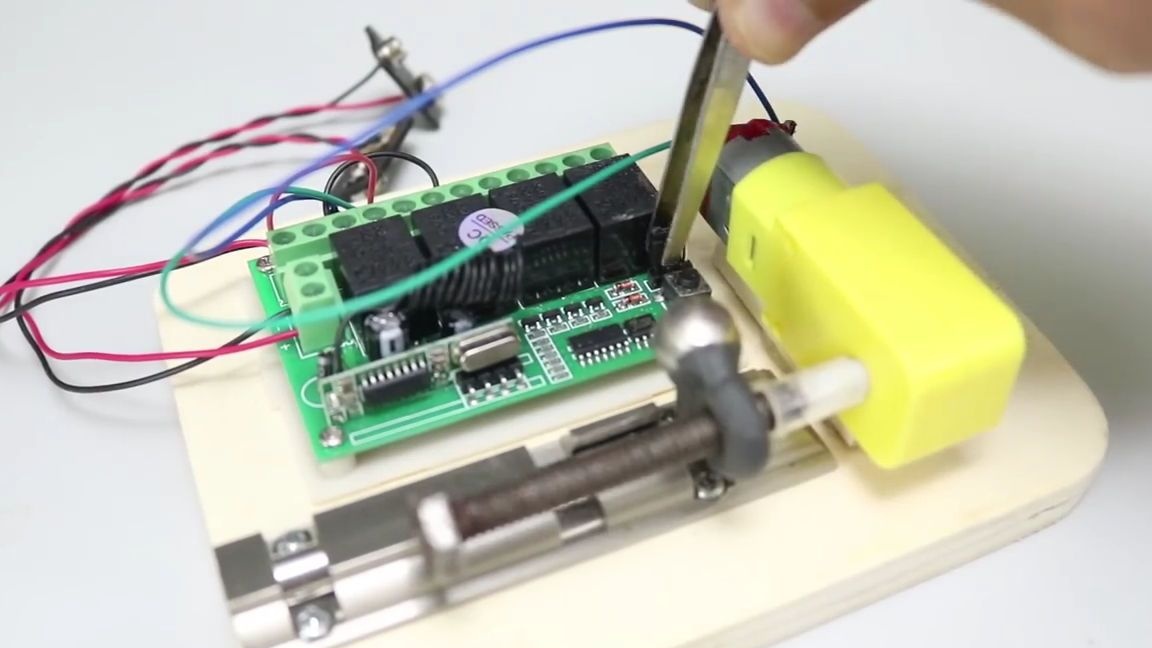
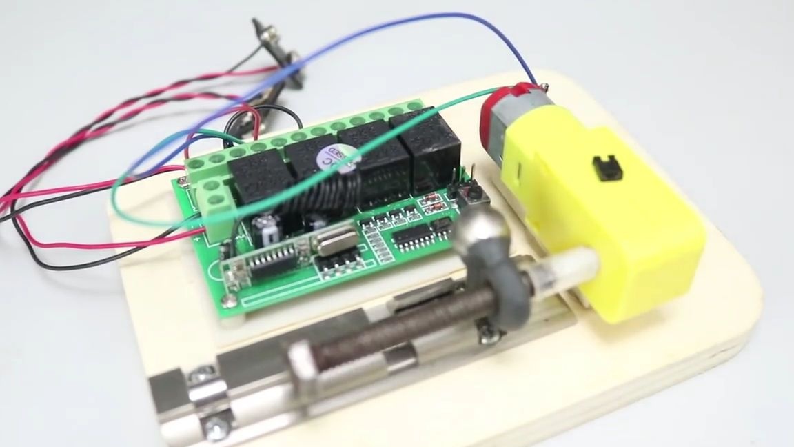
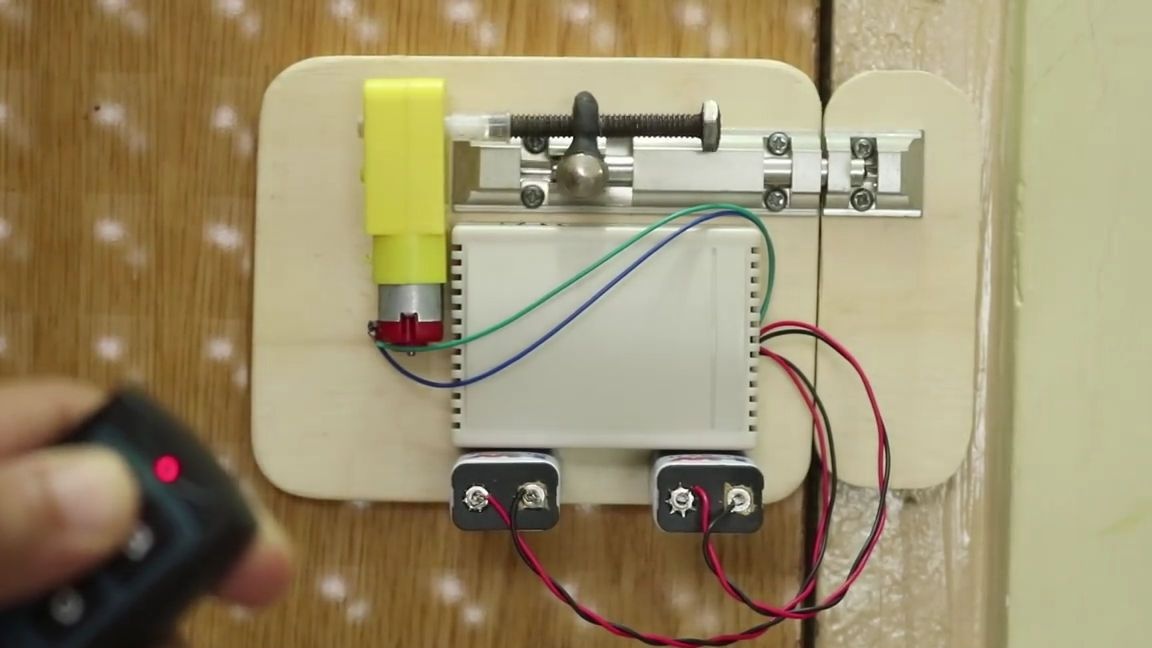
It is necessary to connect all our external electronics to the relay module, as shown in the photo below, the blue and green wires are wires from the motor, and the red and black wires are power wires. This module has clamps for connecting wires, which simplifies their connection, so we take a screwdriver and begin assembly:
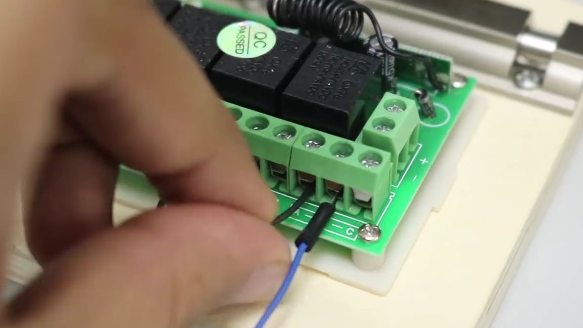
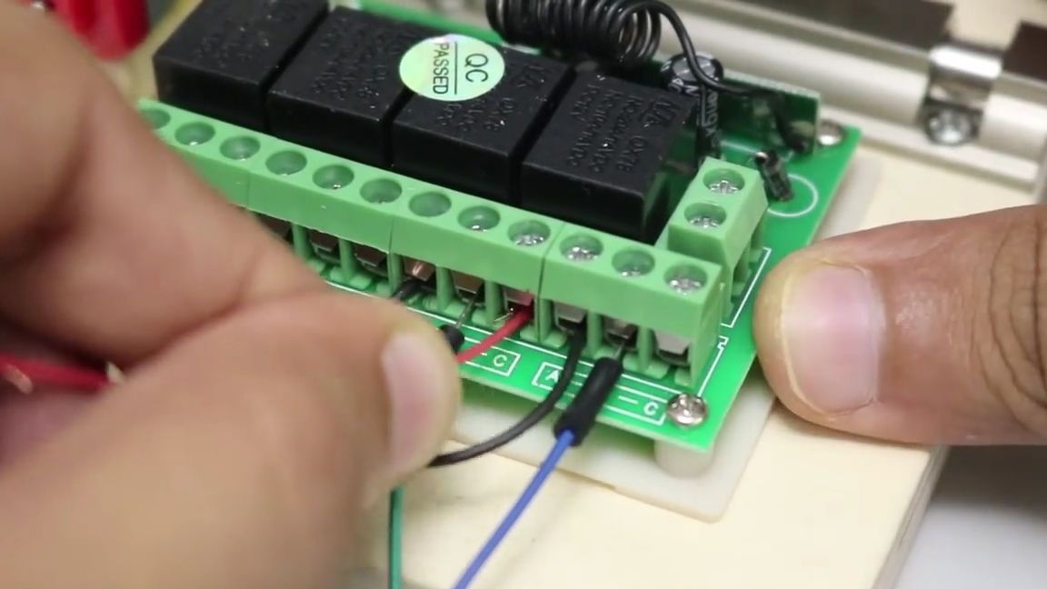
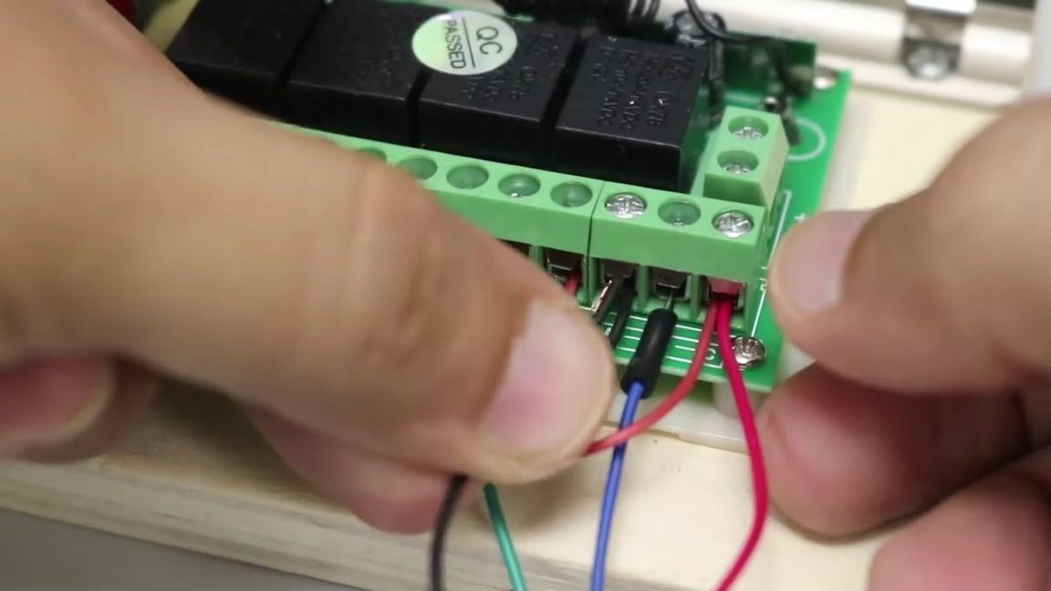
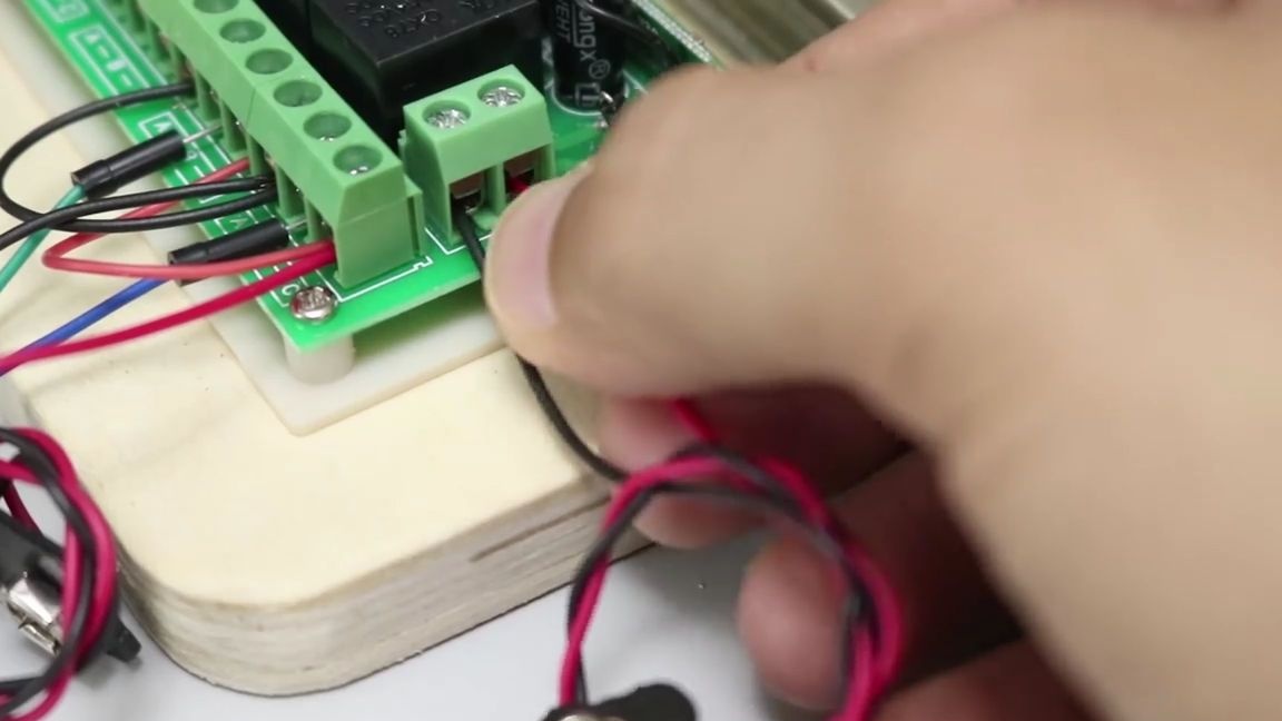
It is necessary to remove the protection with three tweezers from the three contacts on the board:
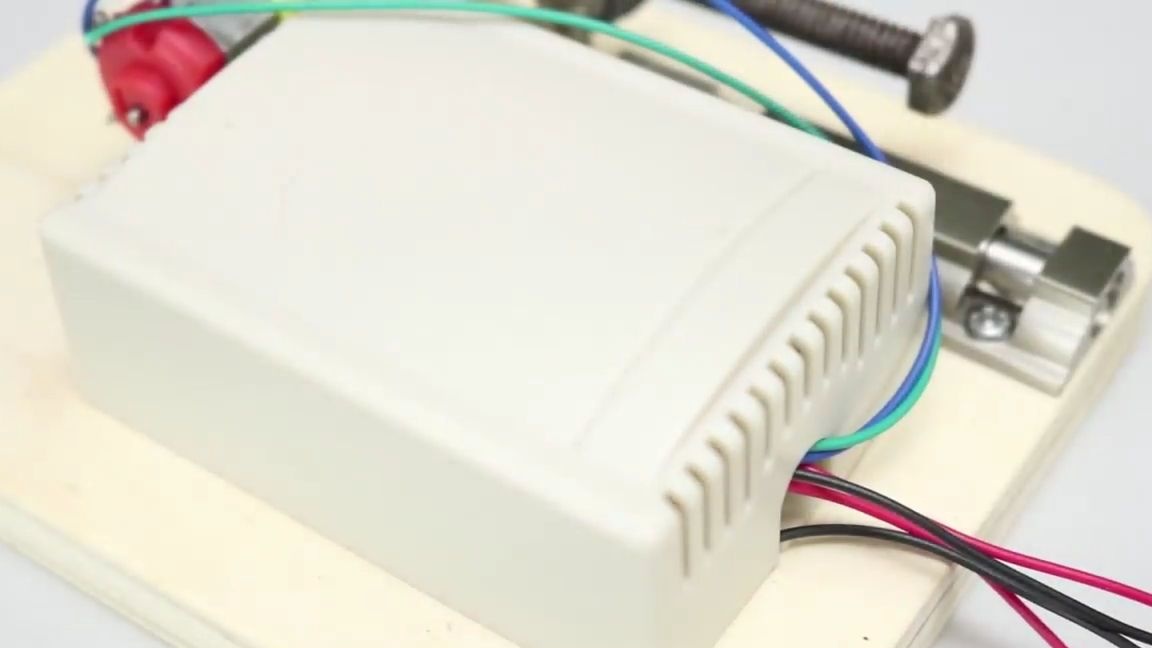
We put the upper part of the case on the wireless relay module:
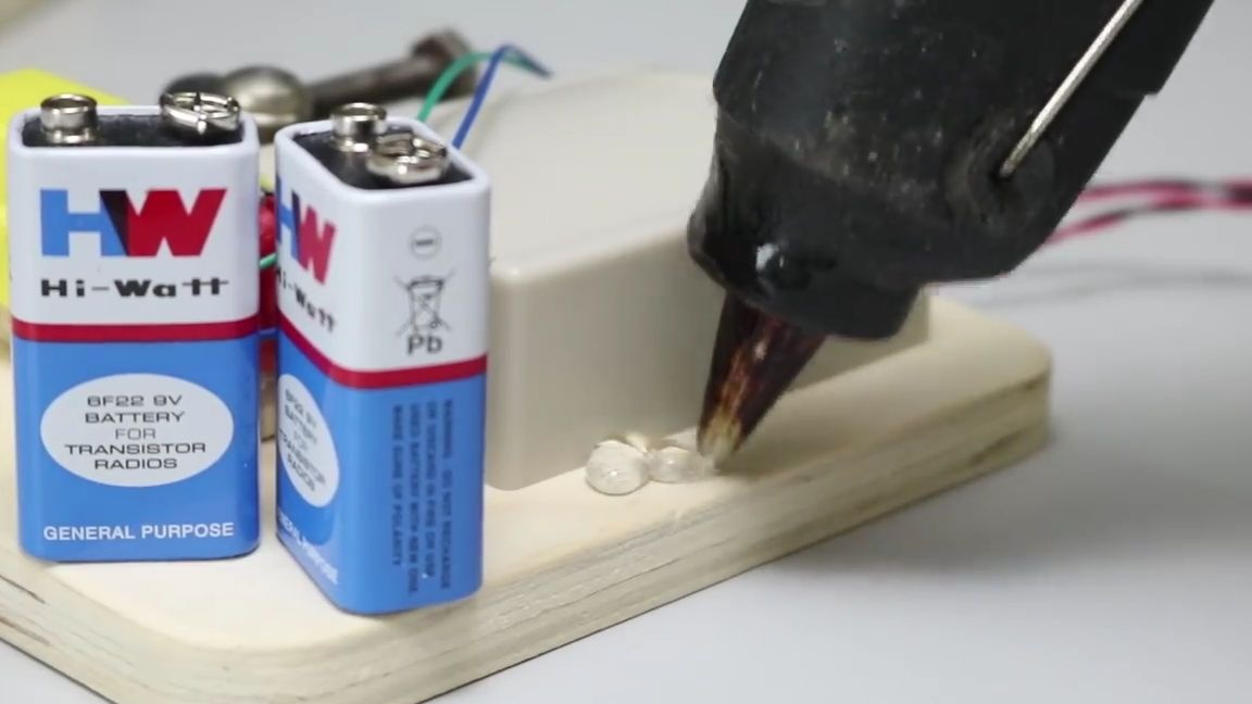
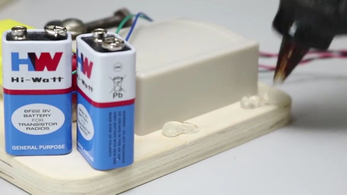
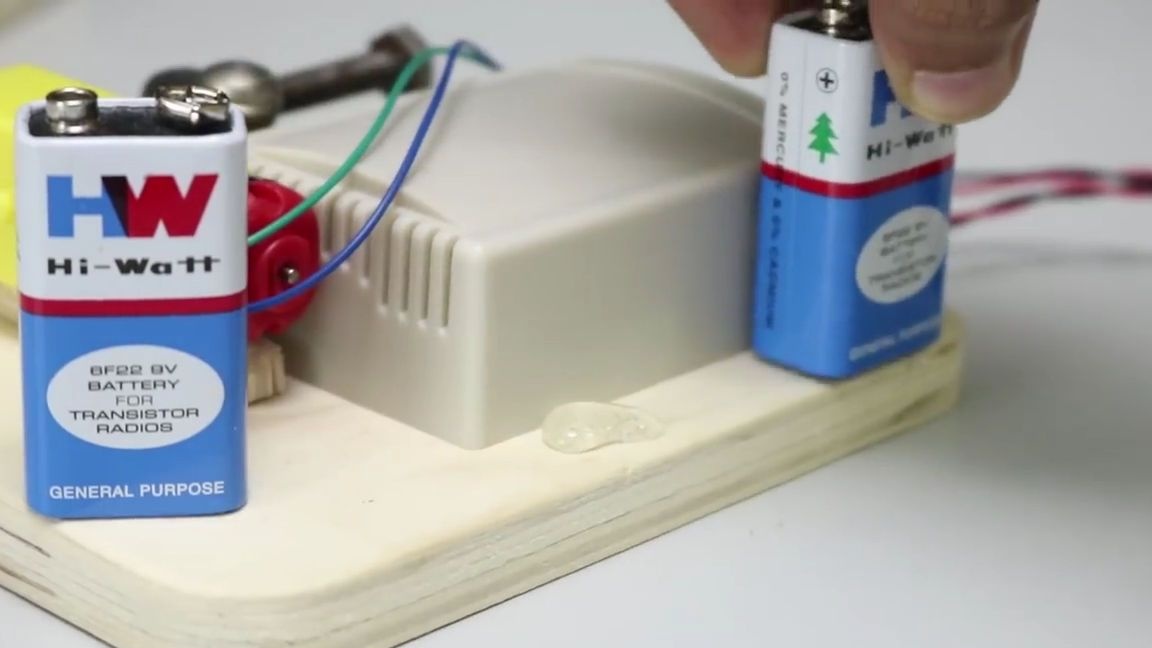
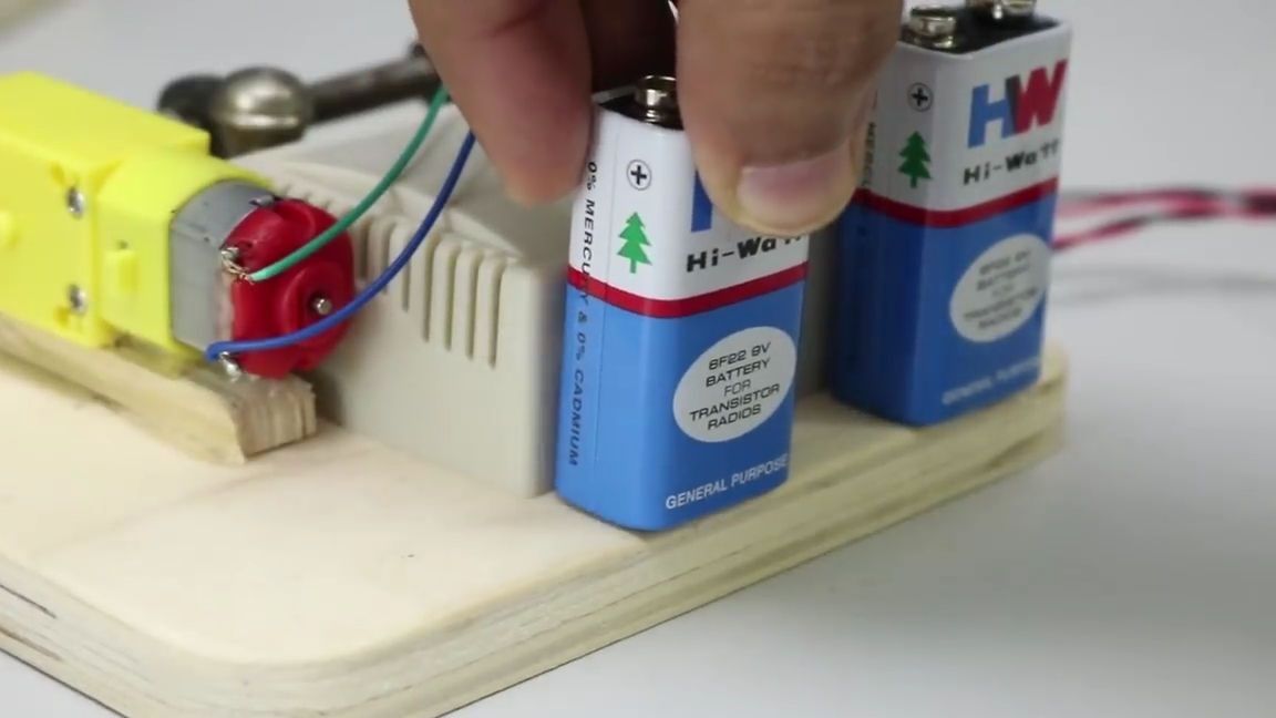
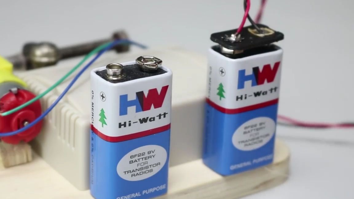
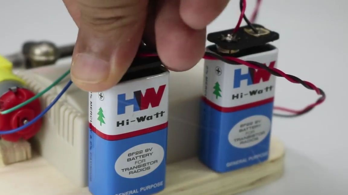
Next to the module, apply a little thermal glue and glue two batteries of the crown type, after which we put the connectors on them, observing the polarity:
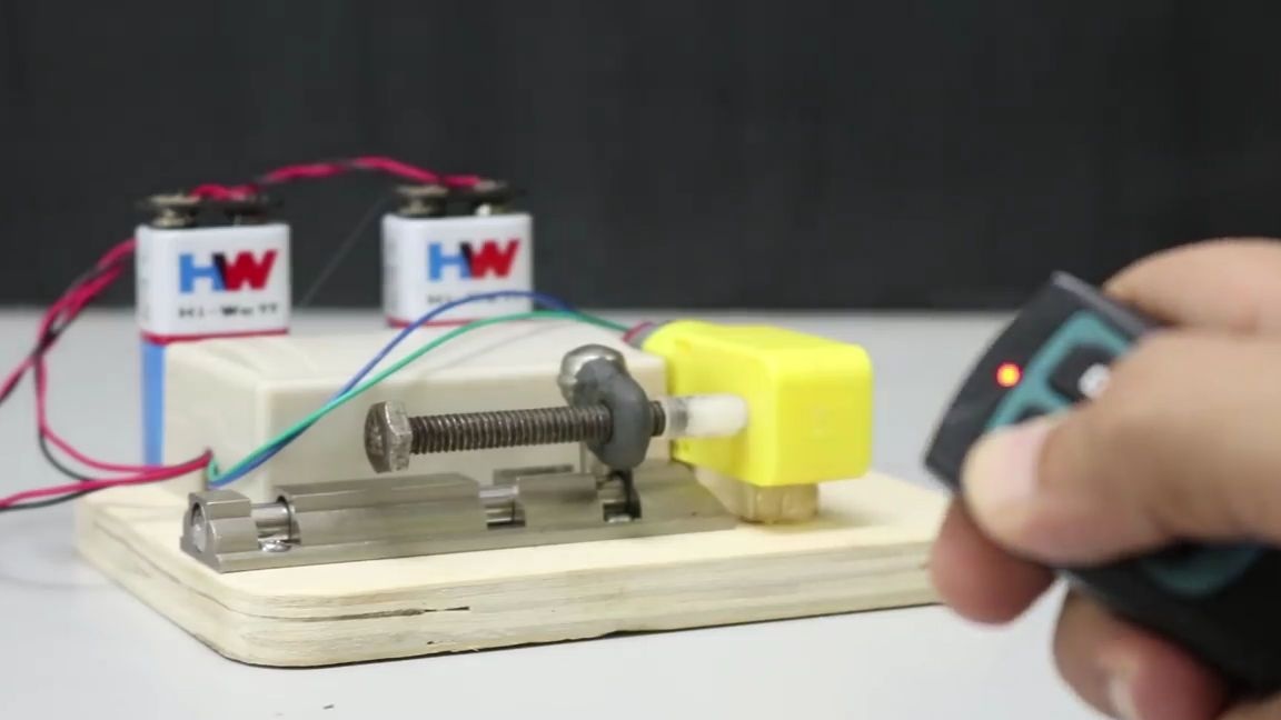
Well, our wireless door lock is ready and it remains only to test it. To do this, simply take the remote control from the module and press the button responsible for the relay, which starts the motor so that it screws the bolt into the nut, and then which is responsible for the relay that makes the motor rotate in the opposite direction. Thus, it turns out that one button on the remote control is responsible for opening the lock, and the second for closing.
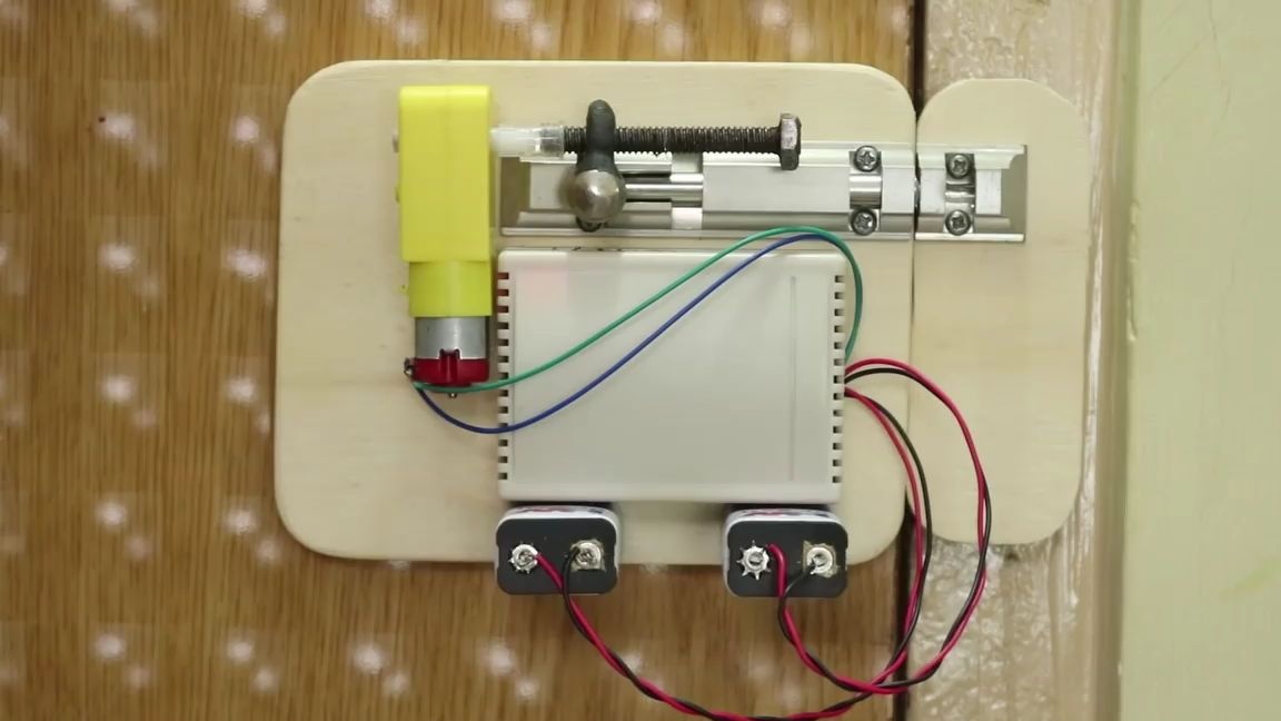
The homemade product is very interesting and not complicated, I think many will want to do the same for themselves, for example, to put it in a room, or on the opposite side of the door of any kind of cabinet.
Here is a detailed video from the author with the assembly and testing of this homemade product:
Well, thank you all for your attention and good luck in future projects, friends!