

We do not live in the country, but we need to open the greenhouse. It begs two exits, to ask the neighbors to open-close in the morning and in the evening, or to drive on their own, which at a distance of 10 km is pretty expensive, and here I remembered the "hydraulic cylinder" from perestroika times. Initially, there were different ideas, from microwave fans installed on top of the ends of the greenhouse and working to extract hot air, to an electric drive with a gearbox to open existing vents. Due to the dependence on electricity, which is often turned off in gardens, these ideas had to be abandoned in favor of non-volatile options.
There are a lot of different options on the Internet on this subject that are fully functional and have the right to life, but it’s not in my rules to blindly copy other people's products, I always bring in something of my own. In general, I bring my product to the court of people.
For the manufacture of this unit will need the following materials and tools:
1. Car fire extinguisher OP-2 (3 liters)
2. Gas spring VAZ-2108 or similar.
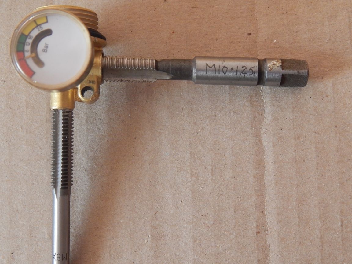
3. Brake hose (I don’t know why, but the tips have M10x1.25 threads)
4. Window loop (I will show in the photo)
5. Small furniture corner
6. Cable tension 12 mm.
7. Used engine oil 3.5 liters.
8. M8 nuts
9. Screws with a drill.
10. Sealing materials (FUM tape, silicone or paronite gaskets)
Instruments:
1. Bulgarian
2. Drill
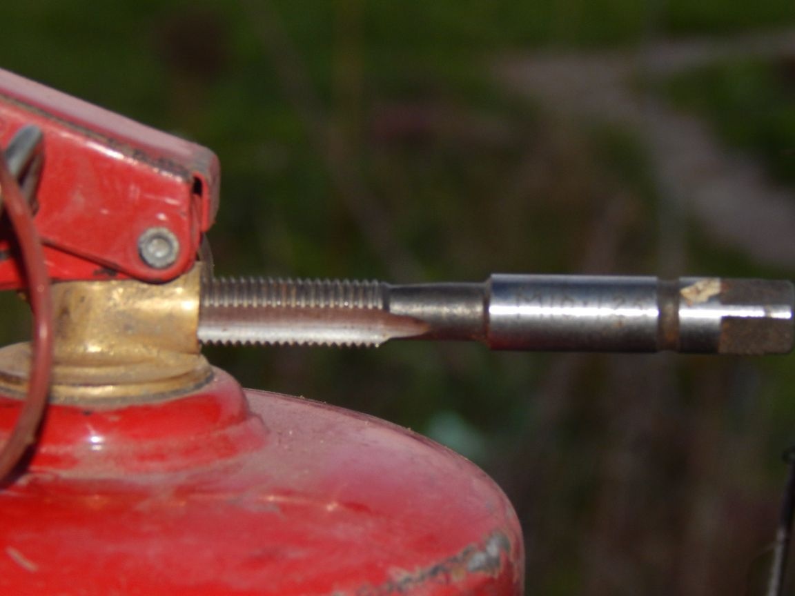
3. Lerka and tap M10x1.25
4. Drills 8.5 mm and 4 mm.
The system consists of two parts - a hydraulic cylinder and an expansion tank, interconnected. This is precisely what the task consists of.
First of all, with “elegant hand movements” we turn a gas spring into a hydraulic cylinder.I won’t describe what it consists of, who cares about the Internet to help, the important thing is that if the gaskets of the spring held gas, then they will hold the liquid all the more, especially since there is already a little oil inside the spring.
The peculiarity of this hydraulic cylinder is that it is completely filled with oil (working out) and the stroke is due to the displacement of the rod volume by the volume of oil expanding when heated. I will describe the mathematical calculations later, but now closer to the point:
We cut off the lower hinge, we will no longer need it. I read on some sites about the complete disassembly of the cylinder, followed by pouring with epoxy resin, in which then a hole is drilled and a thread is cut, in my opinion complete nonsense.
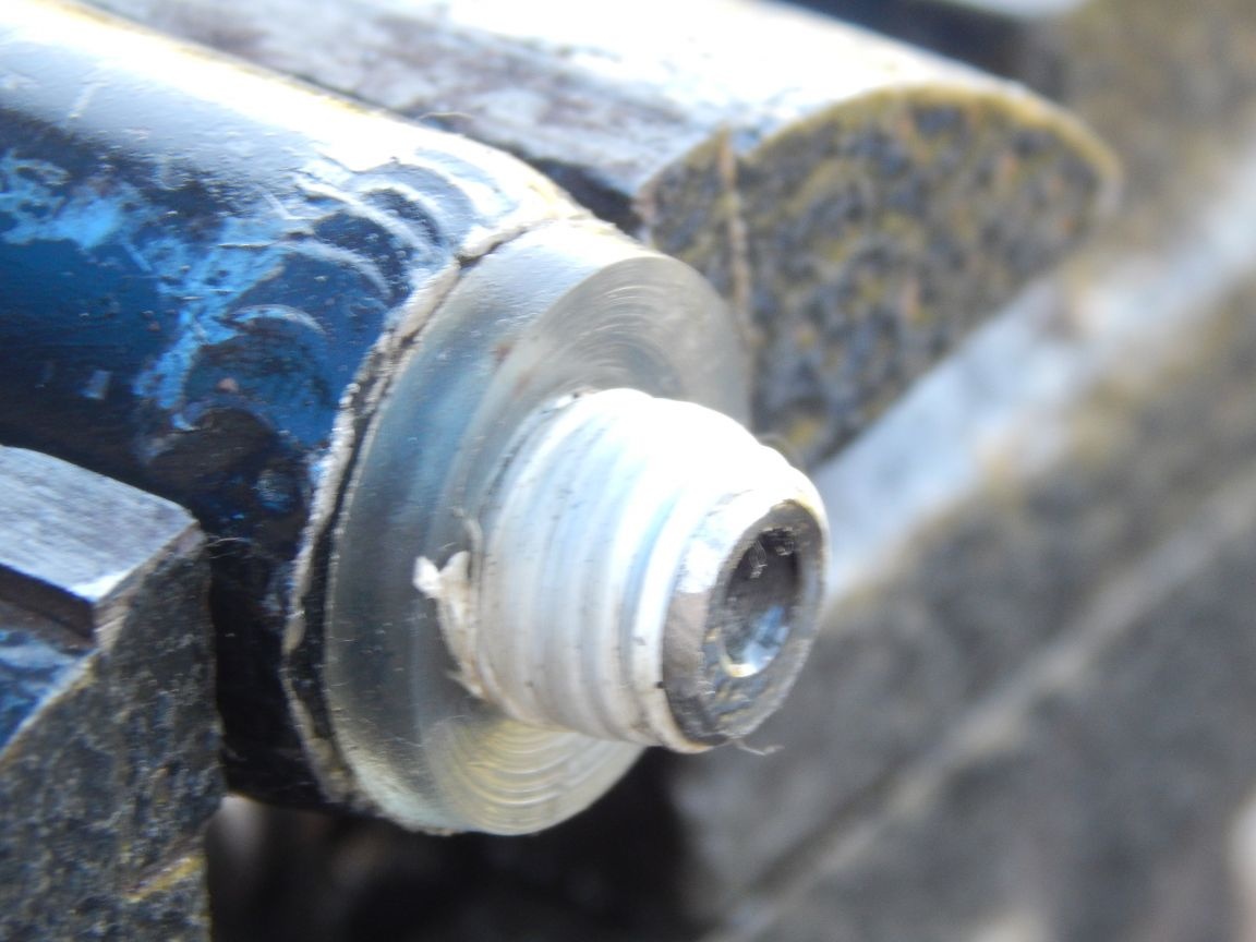
I have an external thread, so we will cut it. By the way, the diameter of the hinge leg is 10.5 mm, which is exactly suitable for our thread and the length is quite suitable.
To thread, slightly grind the leg with a file up to 10 mm.
When cutting, to obtain high-quality threads, we use grease. For lack of sulfofresol, I used the old grandfather's remedy, pig lard (it works even better).
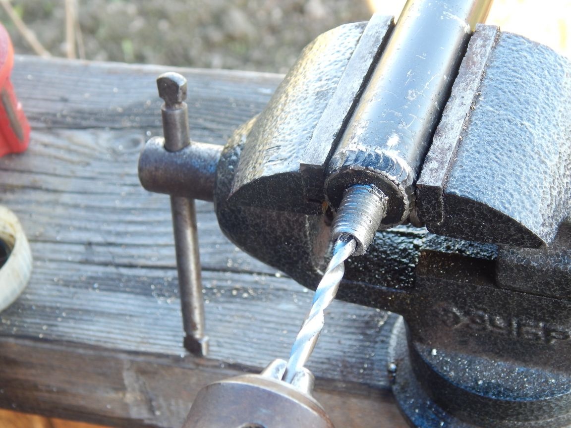
In the end we drill a hole with a diameter of 4 mm. The hole diameter and alignment are not critical, the hole in the brake hose is even smaller.
Be sure to wear safety glasses when drilling! Inside the spring there is gas under high pressure! The chips will literally spit out of the hole, which has a positive side - it will not get inside.
To seal the connection, we use a silicone gasket and, just in case, the FUM tape.
The next step is to make an expansion tank from the fire extinguisher. Alteration, or rather refinement, consists of cutting another thread in the locking and starting head of the fire extinguisher.
We extinguish the extinguisher from the powder, unscrew the head and remove excess parts. We leave only the indicator, it will be as a cork for an extra hole (it still does not show pressure), well, for beauty.
In the outlet (nozzle), we cut M10x1.25 right through the existing M10x1.5 thread (10x1.5 is cut to a depth of 6 mm). This does not affect the tightness at all, we also seal the connection with FUM tape and a paronite gasket, which is more rigid in comparison with silicone and does not squeeze out of the connection.
We cut the M8 thread in the bore of the shut-off valve stem by drilling it to a diameter of 6.8 mm. Oil will be added through this hole during pumping and its volume will be regulated. Looking ahead, I say, 3 liters is a lot for this unit.
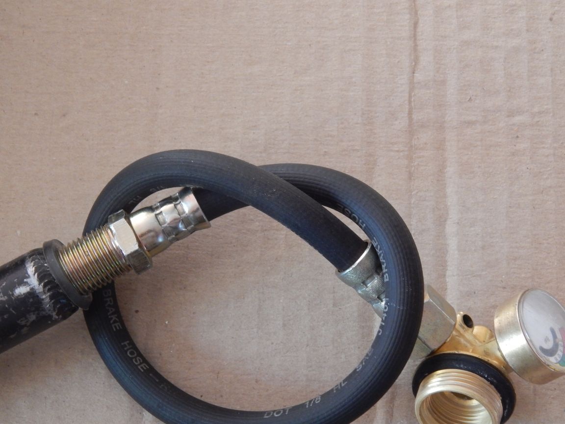
We interconnect the hydraulic cylinder and the expansion tank with a brake hose, which, fortunately, does not need to be modified.
Fill the working out into the fire extinguisher - expansion tank, screw the head into place and pump the system to expel excess air. The bottom line is the following: we fill the tank through the hole for topping up in the head of the fire extinguisher to the level “over the edge”, screw the cork (M8 bolt with the winding tape FUM). The rod of the hydraulic cylinder must be extended to the end. We turn the tank head down and use the hydraulic cylinder rod to reciprocate, expelling the air. The fact that the air came out will become clear by the force on the rod and the termination of "springiness", push the rod all the way and return the tank to its original position, head up. Next, unscrew the cork and add oil, part of which displaced the air in the cylinder. We screw the cork (replacing the FUM tape with a new one) and the assembly of the device is completed, it is ready to work.
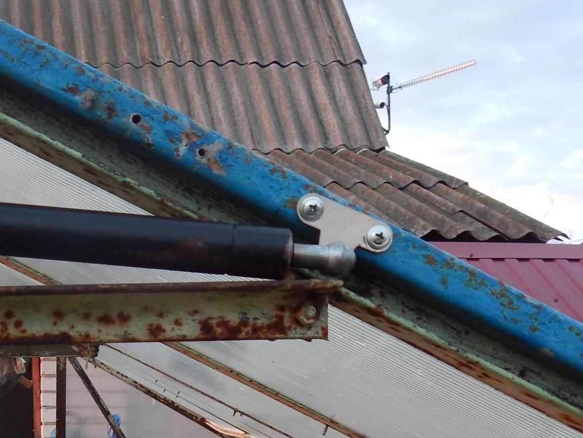
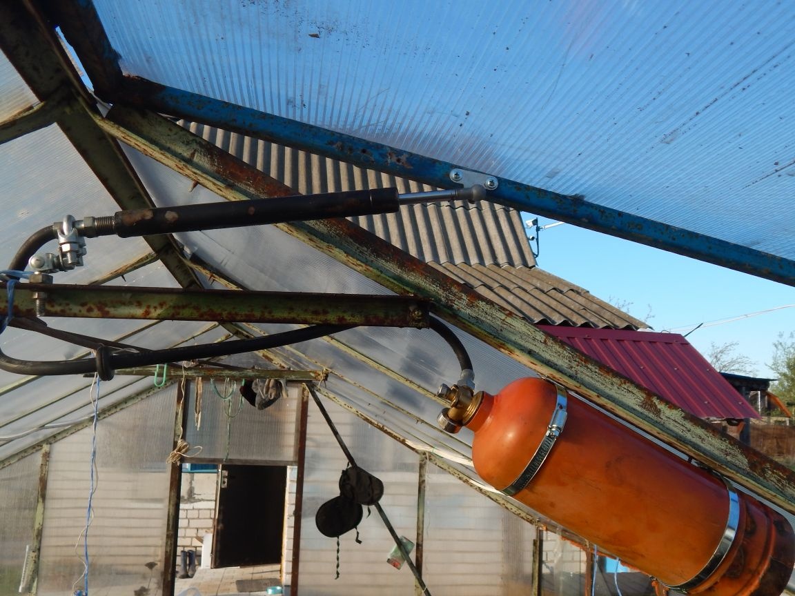
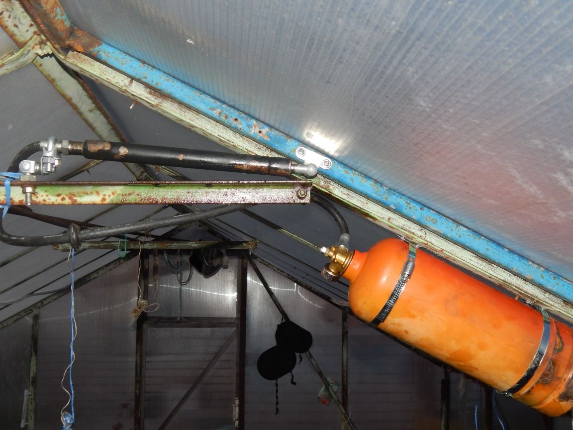
The third stage of design is to install the hydraulic cylinder in place. The hinge on the rod remained standard, and for the cylinder we had to design our own from improvised materials.
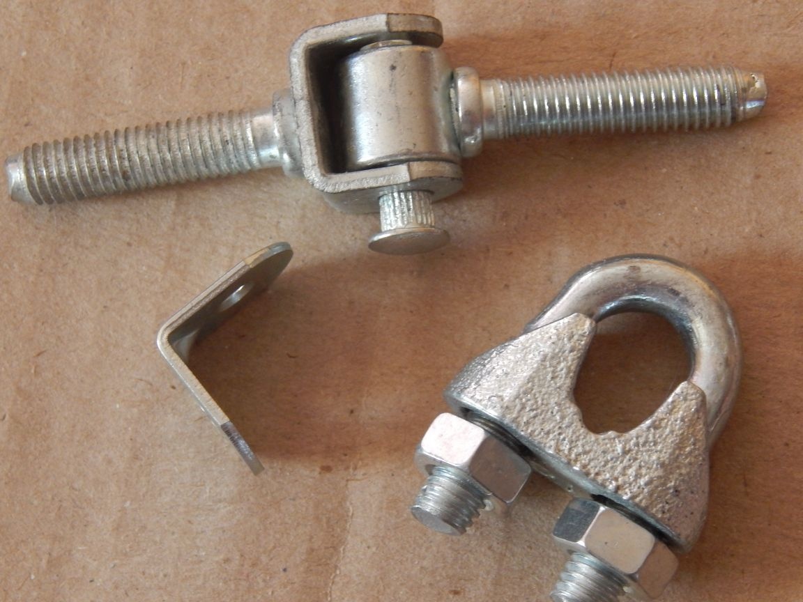
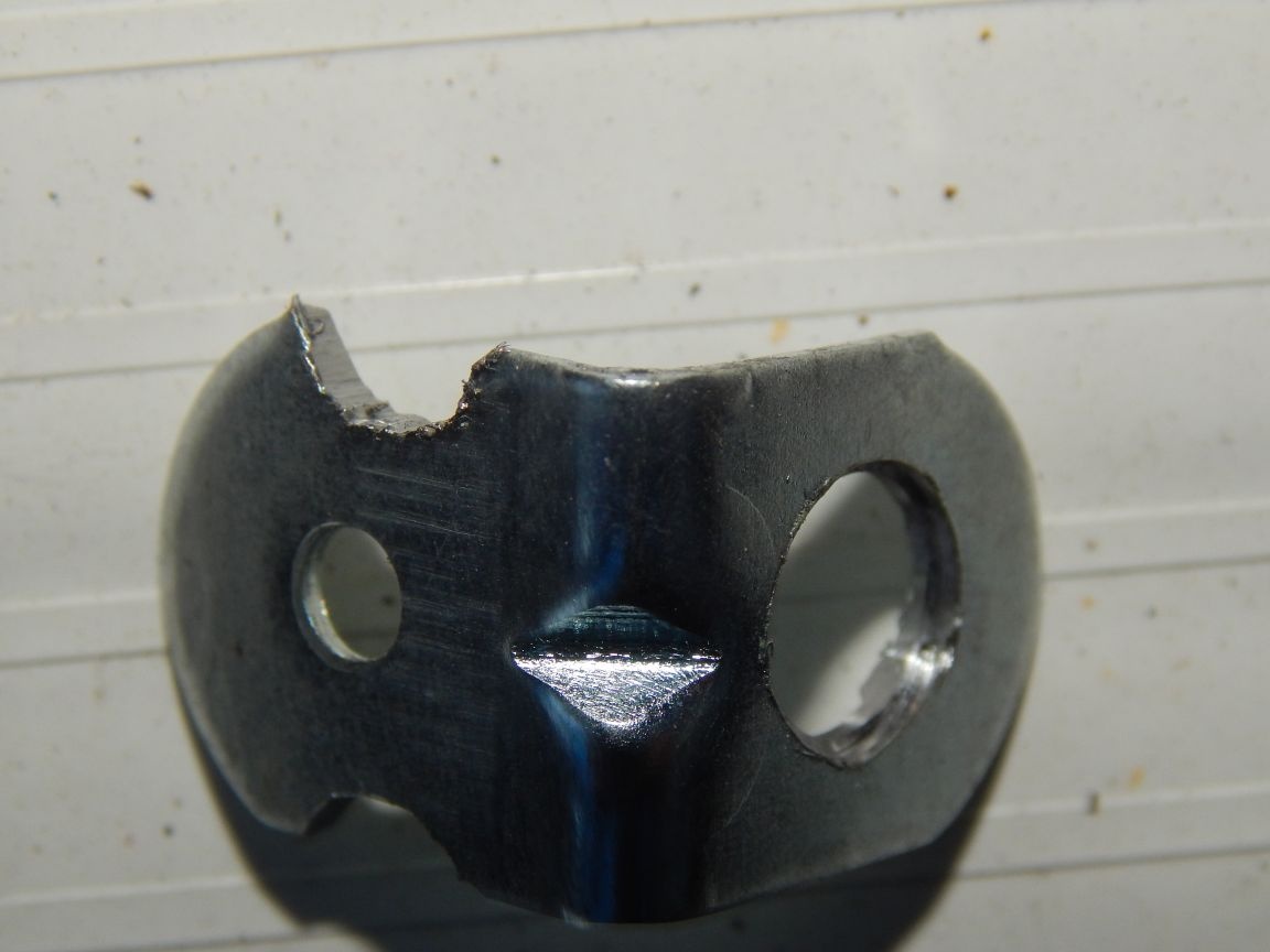
To connect the hinge to the cylinder, I used the smallest furniture corner, having drilled one of the holes up to 8 mm and on the other shelf of the corner I grilled a notch for fasteners with a grinder.
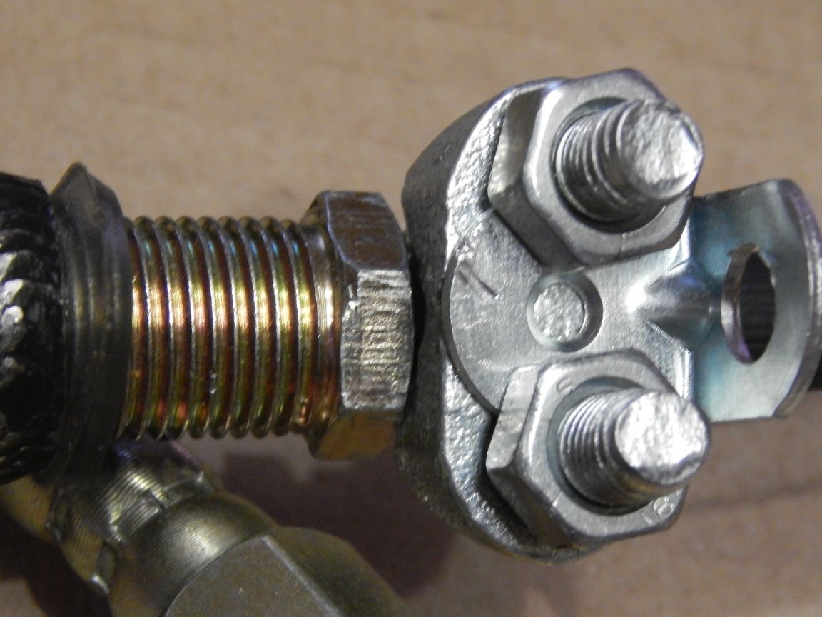
I connected the corner with the cylinder, or rather, with the tip of the brake hose connected to the cylinder, with a clamp to seal the ends of the cable.
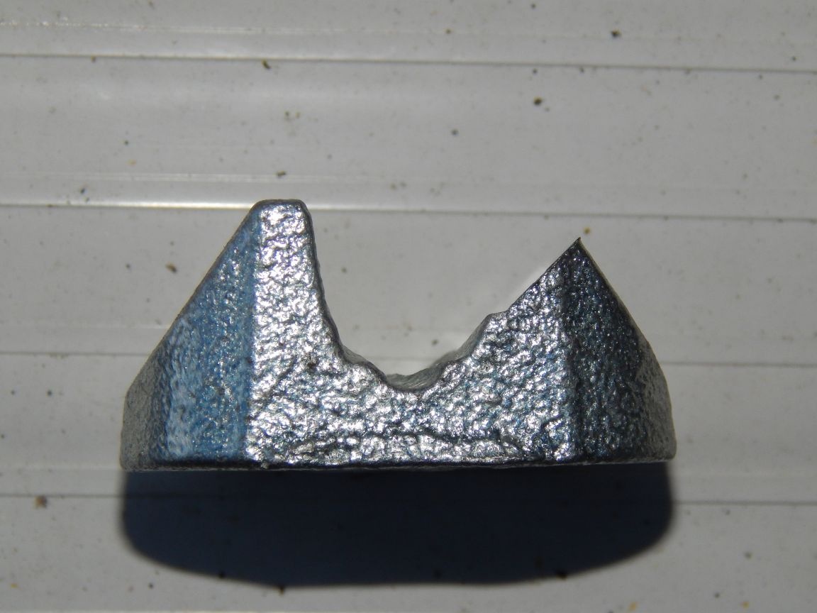
At the clamp, the grinder sharpened the corners a little so that he did not deform the tip.
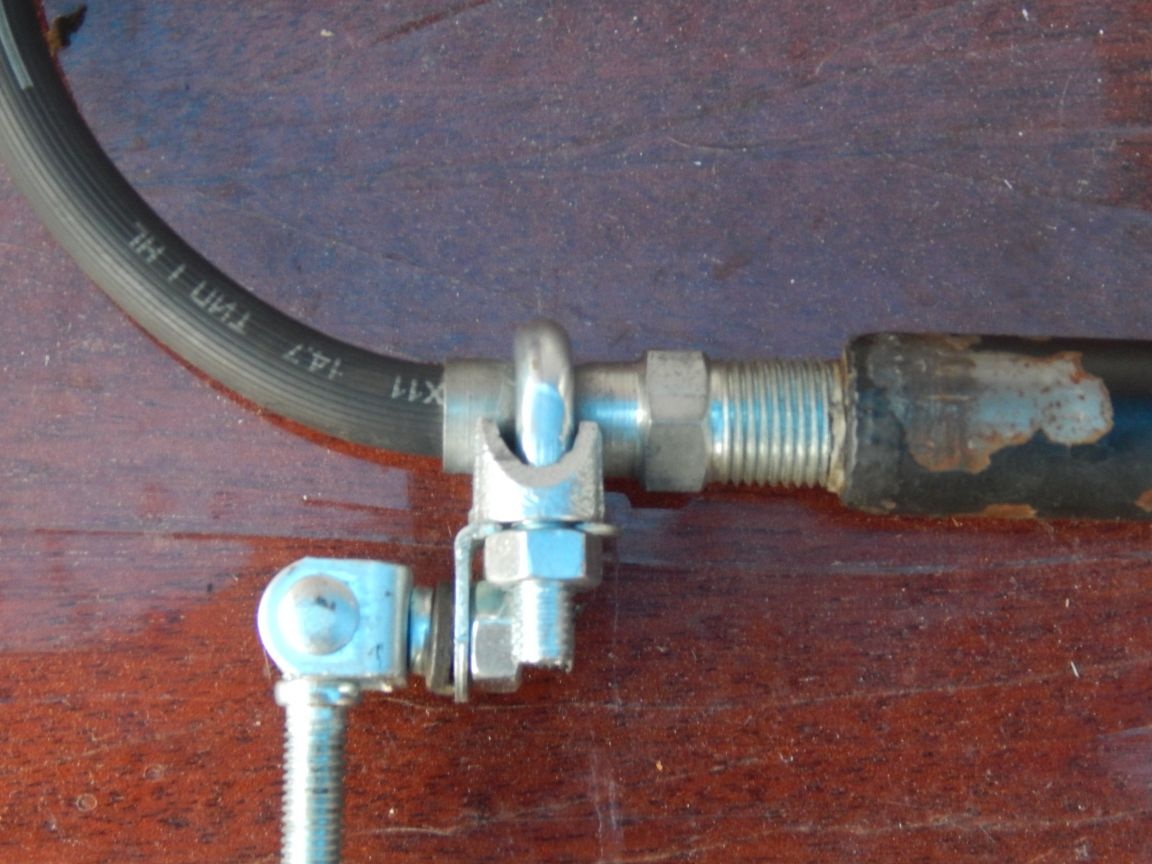
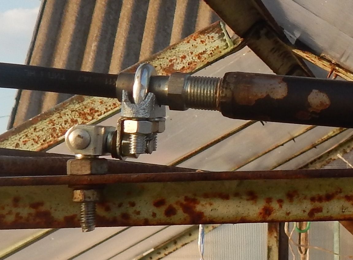
The result is this design:
And with a hinge, it looks like this:
I think it’s not worth describing the installation, the greenhouses are different for everyone. In my already had a jumper corner,
The video of the work of this technique does not make sense, it works very slowly, but I show the photos of some points:
Completely open.
Partially closed.
Completely closed.
Well, now, as promised, I will tell you about the shortcomings of my design.
the volume of the fire extinguisher of 3 liters turned out to be excessive, when heated above 35 ° C in the greenhouse, a little oil was squeezed out through the cuff of the cylinder. According to the calculations for the stem volume of this cylinder, 13.7 cm³ (0.0137 liters) with an oil expansion coefficient of 0.7x10 0.7³ / ° C (roughly 0.07% of the volume by one degree), with a temperature drop of 20 ° C for movement a stock from minimum to maximum is enough to increase the volume by 1.5%, which corresponds to 1.96 liters with a full system. The volume can be reduced using the law of Archimedes by loading metal trash into the tank for a reduced volume.
due to the large volume of oil, thermal inertia increases, it takes more time to heat and cool more oil, which is not a hoot with a sharp cooling.
I have opened the frame is very large, and half is enough for ventilation (by the way, this also applies to the volume of oil and the expansion tank). The cylinder of the times of perestroika, which I wrote about at the beginning, had a stroke of 10 mm in diameter with a diameter of only 40-50 mm, if my memory serves me right.
This device was assembled by me last year, but it was only now installed and tested in business (who would let me stamp the beds with tomatoes in the summer), for this reason some details in the photographs may differ. I hope the article will be useful for summer residents, who will take into account my mistakes in the manufacture of their own design. Now I am collecting a more advanced version, taking into account all the nuances, but now it may not be possible to test it in practice.