» Topics » DIY ideas »Led lamp at 10w

LED lamp at 10w

Very often I came across on the network with an unfair reservation, the Lm317T integral stabilizer, very popular with amateur radio amateurs. They say you can’t use it as a current source for LEDs, since its efficiency is low. After doing a little research, I discovered that the efficiency of this stabilizer drops sharply when the variation in the input voltage is very different from the input, as a current source, the spread in the datasheet is 3 volts, which already provides good efficiency, to this we must add the fact that not need to go beyond 300 ml, since there is also a sharp drop in efficiency. Based on this, such a simple scheme was born.


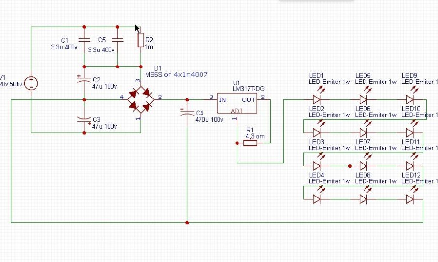
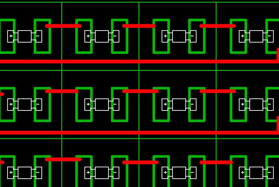
The circuit works like this. From the network, the voltage goes to the ballast capacitors C1-C5, limiting it to a current of 400 ml, then it goes to the capacitor divider C2-C3, dropping to 40 volts, note that the capacitors are polar, but they are included in the alternating voltage, in fact a constant voltage for them they are formed by the shoulders of the diode bridge, and therefore the change is not terrible for them, at the same time the diode bridge rectifies these received 40 volts and they go to the filtering capacitor C4, then the rectified voltage is applied to the current source built above omyanutom Lm317T, the current source output is supplied to diode assembly of emiternyh 1 watt LEDs connected in series. Since there are 12 LEDs, the required total voltage drop on them is 36 volts, and the current obtained after Lm317T 0.288A, then, the power of our lamp will be 10.3 watts, the lamp turns out underloaded by current, and for this reason it will work in a more gentle mode, which will positively affect its service life. Since the filter capacitor we have a sufficiently large ripple capacity on the lamp is only 4.5%, which is very good. That's how we got a relatively inexpensive and economical ice lamp 10 watts. The only drawback is its dimensions, as it is clear from the printed circuit board that the ice was placed on a circuit board measuring 130 x 90 mm for better cooling, to reduce the dimensions of the lamp, you can try using a multi-layer aluminum profile.


I use her at home as the main lighting.
Question \ topic is automatically published in the social. site network - stay tuned for answers there:

Suitable for topic

Related topics

Add a comment

    • smilesmilesxaxaokdontknowyahoonea
      bossscratchfoolyesyes-yesaggressivesecret
      sorrydancedance2dance3pardonhelpdrinks
      stopfriendsgoodgoodgoodwhistleswoontongue
      smokeclappingcraydeclarederisivedon-t_mentiondownload
      heatirefullaugh1mdameetingmoskingnegative
      not_ipopcornpunishreadscarescaressearch
      tauntthank_youthisto_clueumnikacuteagree
      badbeeeblack_eyeblum3blushboastboredom
      censoredpleasantrysecret2threatenvictoryyusun_bespectacled
      shokrespektlolprevedwelcomekrutoyya_za
      ya_dobryihelperne_huliganne_othodifludbanclose
28 comments
The author hopes that there will be no negative voltage on the electrolytes c1 and c5 due to the shunting of the bridge diodes, but it will still be - due to the fact that silicon diodes have a significant voltage drop on them, it is therefore indicated in the dialogue above that the electrolytes will gradually degrade. The design is suitable only to try and satisfy the vanity of the designer. Its long-term operation is simply dangerous, like any uncertified homemade assembled on the knee. Moreover, if the lamp is left unattended for a long time in the on state. Estimate all the risks and buy a better new one in the store, especially since they now have significant discounts of up to 50-100 rubles. a piece.
Author
Unfortunately, you turned out to be right, this is what Dmitry Korzhevsky, my esteemed me, answered the grateful YouTube channel subscriber I am: "Indeed, ripples on electrolytes over 20% can lead to their heating, or loss of capacity. The degradation time greatly depends on the brand of the conductor and its qualities.The fact that they worked for 2 years does not mean that they are not afraid of such a regime.
I would throw out C2 and C3, and replace C1 and C5 with a smaller capacity conder, which I would select experimentally, until the voltage regulator reaches the input voltage. At the same time, C4 would turn on a zener diode, preferably not the weakest, for a voltage slightly higher than for C4 (with a connected load, of course). It is necessary to suppress power surges when turned on. For the same purpose, it is necessary to include in series with a network wire a resistor of several tens of ohms and a power of 1-2 watts. Resistance should be chosen so that it is warm, but not hot. It is desirable to double the capacity of C4. ".
That is, in the circuit, the capacitor C2-C3 will lose capacity over time, since I have 4 such lamps assembled, and they actually perform their function (well, do not disassemble them for me), I will leave them in work to complete the experiment, while continuing research for a simple and cheap ice driver, I can’t follow Dmitry’s recommendations, at a power of 10 watt an ice lamp requires at least a 10 watt Zener diode, which is unacceptable, or a powerful analog of a zener diode, then you need a powerful transistor with radiators capable of dissipating this power ... here why start with wipe away towards the pulsed current source ...
Thank you Pronin for sowing doubt, and shook my confidence, where doubt appears anxiety, and anxiety is a favorable environment for reflection ...
Author
By the way, I know who will judge us, there is one very competent person, I will turn to him in order to give his verdict to this scheme, and I will publish our conversation with his permission here, or maybe I will invite him to this conversation ...
Author
Throughout all 20 comments, I have been asking you, my dear Pronin, to describe specifically all the flaws of the circuit, please provide at least the links that provided these technical and electrical standards, if you have any information, I have given my counterarguments to all of your arguments earlier , and if everything continues in this vein, then our conversation loses its constructiveness, and forgive me, but it loses its meaning ...
What I wrote to you (2 times) about electrolytic capacitors, you did not understand. You have not passed any TOE and you want to somehow explain the flaws of the scheme in everyday language.
<... but the fact that they have a poor spectrum and ripple is another conversation, specifically that has nothing to do with this scheme,> Why then do you need these bulbs in general? scratch
Author
I did not compare the Cll lamps with the LED ones, I just said that in the cll lamp, and in the above diagram, electrolytic capacitors are used, as for the longevity of the cll lamps, you should not have worked for three years or more, but what the spectrum is poor and ripple is another conversation, specifically having nothing to do with this scheme ... your arguments are weak.
By order, the CFL lamp fashion was launched. To replace incandescent bulbs (which are uneconomical). Ketai provided supplies. But, as it turned out, the resource of these CFLs is not great at all. They die for various reasons ... And the price is rather big.
It is not clear how you compare CFL and LED lamp. These are actually different light sources. And they are fed differently.
A person’s vision adapts to the light ... But, if the light spectrum is "bad" or blinks (almost imperceptibly), then fatigue, headaches, etc. are irrelevant. You can roughly check the light bulbs. For example, using a photodiode ... and an oscilloscope. To see the pulsations of light (in%). I have long conducted such a test to find out an acceptable lamp for me.
Author
Bati has been in the garage for almost the second year, a similar lamp of 5 watts has been working, and given that the garage is not heated, the internal resistance of these Conders increases in winter, which is not good for them, they should start to warm, degrade faster, but at the same time the lamp brightness does not drop visually, then let me ask you, over time, how much is it? For normal electrolytes to work correctly, polarizing conditions are necessary, they are in this circuit. Regarding ripple, in the CLL lamps there are 3.3 microfarad filter capacitors at the input after the bridge (there’s more ripple here), but they popped only a couple of times in my eyelid , in my scheme, the condenders are 47 microfarads! Next, we take any simplest laboratory power supply, which has a filter capacitor after the diode bridge, if it is designed for a maximum of 30 volts, this voltage is supplied, for example, a lab technician is designed for 2 amperes, from they are also removed, that is, by indirectly outputting a 470 microfarad converter at 63 volts, it will easily receive and give this voltage and current, in the circuit shown by me the current on capacitors and a diode bridge is several times smaller, 0.3-0.35 amperes . This morning I thought to increase the reliability of the circuit it will be useful to put a diode bridge on 1 amp all the same, DB107 is suitable, given the bursts when turned on. You are confused by the fact that the electrolytes are switched on after the ballast capacitor, it seems between phase and zero, but you completely do not take into account the inclusion of diodes of the diode bridge with them, the polarization of the capacitors is set by these diodes. You propose to exclude these two electrolytic ones, which are unreliable according to your inclusion, and connect the LEDs after the bridge through a quenching resistor, well, I propose to go with me to this site and let's calculate together which resistor is needed, given that after the ballast and diode bridge with filtering conder in the circuit, the voltage will be 310 volts, in the column Power supply voltage (V) and set it, select the direct voltage of the LED at 3 volts, the direct current of the 1-watt LED, I chose 266 ml, maybe more, but I want to save I put that device, I put 12 LEDs, after pressing the calculation button, we get that we need a resistor of 1 room 73 watts !!!!!! That is, there is absolutely no efficiency of such a circuit, moreover, the dimensions of the filtering capacitor will simply be unacceptable, since at least a conder will be needed at 200 microfarads 450 volts. The circuit with a quenching conder and a voltage divider on electrolytic capacitors is devoid of all these shortcomings, the driver dimensions are acceptable, 6 cm x 4.5 cm.
I don’t already know what arguments to give in defense of this scheme.The circuit works, and it is not more dangerous than the circuit of an electronic ballast of Cll lamps, though a fuse is necessary ...
Something flickers colorfully ... There the load Rn in real life will be less and imp. currents are greater.
Electrolytic capacitors quickly degrade in this inclusion. Maybe they will even swell.
Author
I take my words back about the remote URL, the browser glitches, my apologies
Author
you can ban me, but deleting the link to the simulation is not good, http://tinyurl.com/y886eer6
Author
if you reduce the simulation speed, you can make sure that the current on the capacitors rises no more than 0.3 amperes, the voltage on the capacitors is no more than 24 volts that it will be in this mode, the fireworks will burn if the diodes in the diode bridge burn, but they can be double in the diode bridge, diodes are 1 ampere, but this is redundant, since the consumer current is 266 ml, the other bridge in the construction is 500 ml, almost with a double margin ... and now there are no electrolytes without notches, and those with notches do not explode just burst, the only thing that would not hurt before 0.5 amp fuse, that's all ...
Author
Dear Pronin, this is what the simulation of this scheme says http://tinyurl.com/ydepbb27, what are your thoughts on this.
Author
Here the BP2832A ordered by me will arrive, as I check them in work, from me the circuit and the overview of this already impulse driver ...
Author
Yes, I agree with the time that capacitors degrade, but nothing lasts forever under this sun :)
This circuit is their w-Radio ... And there was a case, a man took a simple power supply circuit. Practical, from the Radio. To power the unit at work. Everything was at its limit there. And the load current is decent ~ 2A. At the output of the filter were 2 cans, either K50-16, or K50-35 (without a forced groove). There was not enough capacity (the calculation was not done). And there was a voltage drop (~ 35%), which was smoothed out by the stabilizer ... People noticed that the condors were very hot and climbed off from the outlet and one conder exploded and an aluminum glass (shell C) hit in the head.
In your case, C may degrade. The capacity will decrease. There will be less current and the lamp will become even more economical.
Author
And here the currents are small 260 ml ... I took the whole theory from here, and there are calculations for all this, if the electrolytes were not in the mode, they would have pulled me off, and they work like that and do not heat up at all, I have on the table the assembled lamp, I’ll take it to the test, that is, I will measure the current on electrolytes, I won’t argue ... I will not collect the circuit;
The main thing in this circuit is the correctly calculated quenching capacitor. And the change divider is on electrolytes, it is for low currents (<20mA). And for decent currents - special capacitors (non-polar). Here is a modeled oscilloscope. U on capacitor C3 (blue) and on capacitor C5 (red). With Rн = 160. Swipe Uimp -1.1V to + 34V
Author
the electrolytes C2 and C3 are fed through the diagonal of the diode bridge, and this is not superfluous, they lower the voltage to 40 volts, google a capacitor power supply with a capacitor divider, lowered the voltage for LM317, as well as for LEDs, I know that LEDs are powered by current rather than voltage , but from practice I noticed that the amplitude on the LEDs also plays a role, as soon as the LEDs get into their voltage and current, the overheating stops, and they start working in their mode, the circuit is absolutely working, don’t be afraid the peasants will not break anything, Learn the circuit at the beginning ... I myself at first began to boggle at the strange inclusion of these Conders, but having assembled the circuit, I checked it for operability and also for security, believe it or not, I have 4 lamps on this circuit, it has already been 3 months .. .
On electrolytes C2 and C3 there will be pulsations at 100%. And the permissible 20%, at best. They are superfluous here. It is better to reduce C5, as an option.
Author
Recently I tried to use a t-shaped aluminum profile for the lamp, used 1 watt emitter LEDs, glued them to the profile with thermally conductive silicone, everything worked properly and reliably, the design has very good repeatability ... here is the PCB for the driver
Author
On the Internet, I found an idea how to use CFL ballast as a driver for a 10-watt LED lamp, yesterday I checked and selected the elements so that the lamp is in mode, the driver fits the same matrix as in this homemade product, if I can interestingly design and share, the idea not mine, but still interesting ...
Author
here is the final version
Author
Admin do not rush to publish now I will send another picture, given the discharge resistor of the ballast capacitor
Author
here is the correct diagram
Attach the correct outline in the comment and I will replace it in the article.
Author
It is true in the circuit, the error output should go from the foot of the Adj stabilizer, I would fix it but I can not find how.
Correct the scheme.
And in parallel to C1 and C5, a resistor of several hundred kilos will be very correctly added.

We advise you to read:

Hand it for the smartphone ...