
Hello to all lovers homemade. In this article I will tell you how to make a tester of transistors and other radio components do it yourself, in the assembly of which the kit kit will help, you can order it by the link at the end of the article. This tester allows you to check radio components such as transistors, capacitors, resistors, as well as inductors. On its screen, all the necessary information about the connected component is displayed, and also when the transistor is connected, the pinout of the terminals is displayed, which is very convenient.
Before reading the article, I suggest watching a video where the entire process of assembling a kit kit and its testing on various radio components is shown in detail.
In order to make a tester of transistors and other radio components with your own hands, you will need:
* Kit
* Soldering iron, solder, flux
* Side cutters
* Device for soldering "third hand"
* Phillips screwdriver
* Multimeter
* Battery "Krone"
Step one.
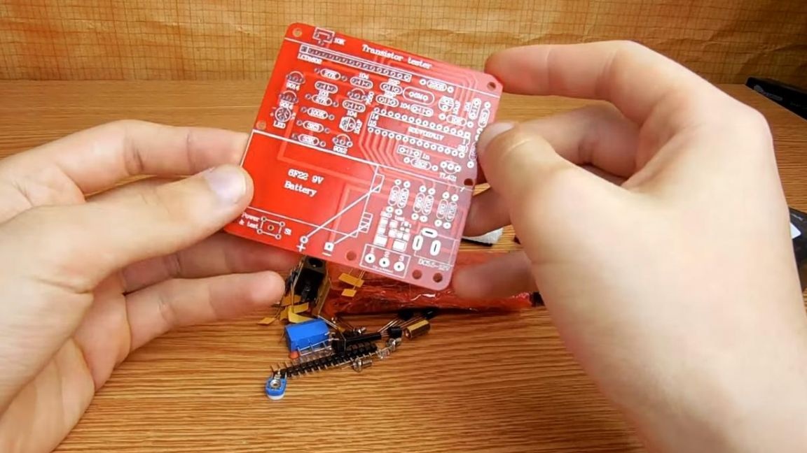
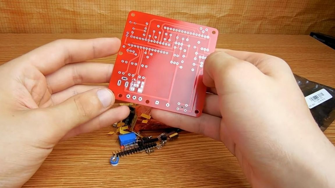
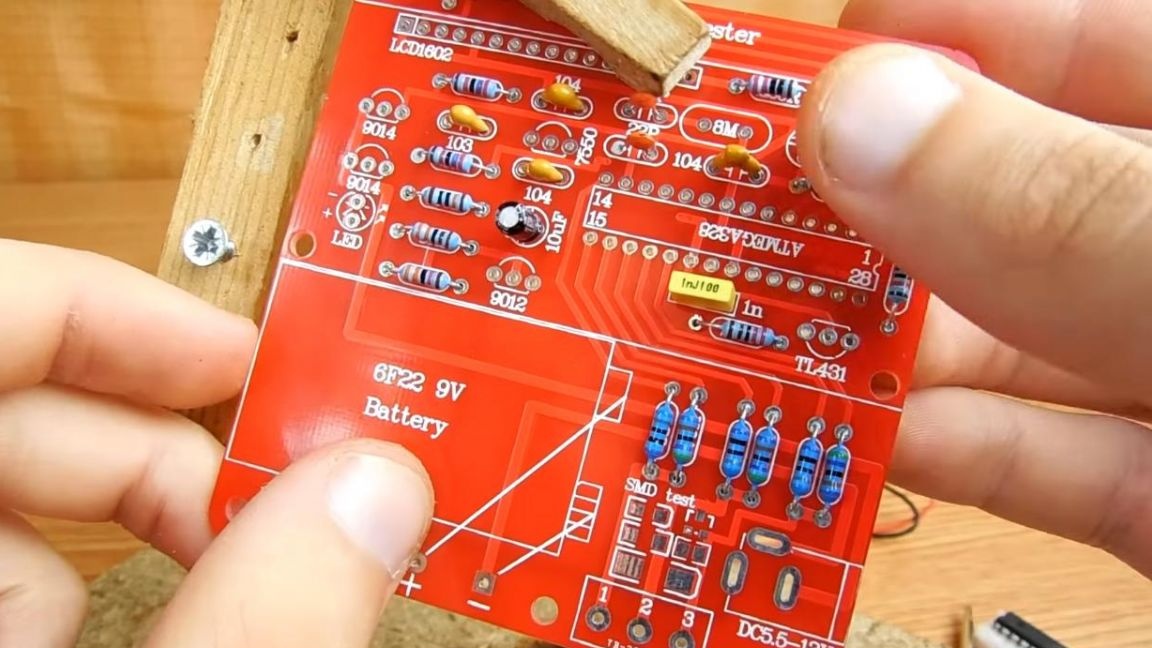
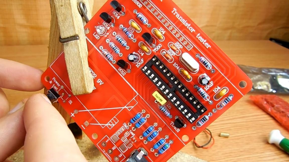
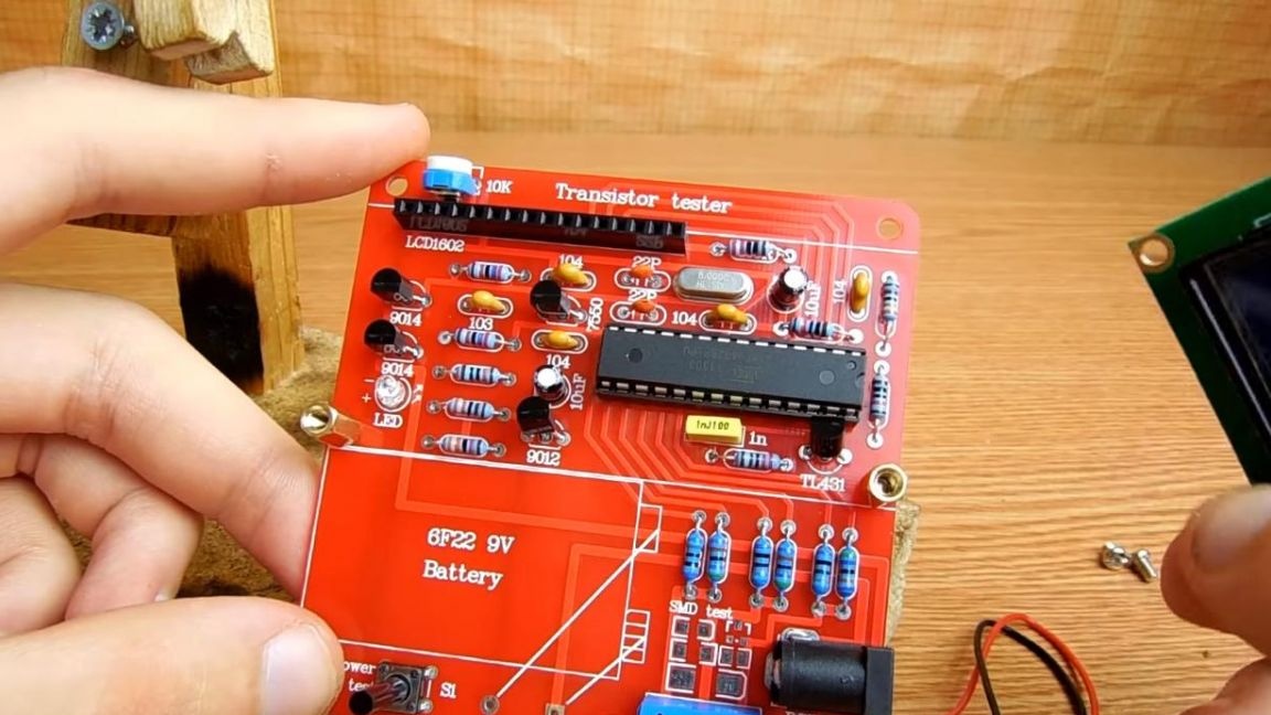
The kit comes with a large double-sided printed circuit board with metallized holes, its quality is quite good.
First of all, install the board in the soldering device "third hand" and
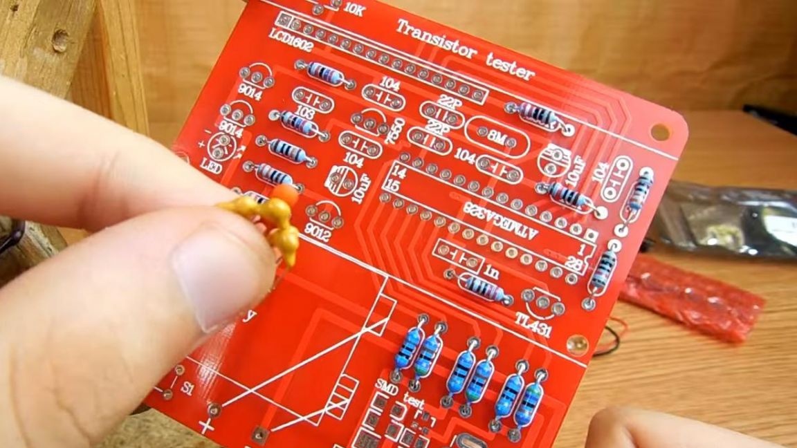
we begin to put the components in their place, there were no instructions for the kit, but everything is well signed on the board.
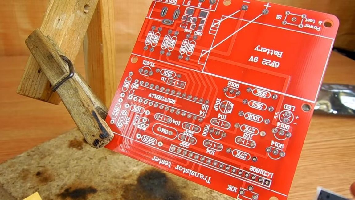
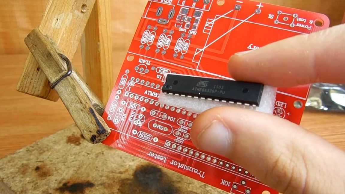
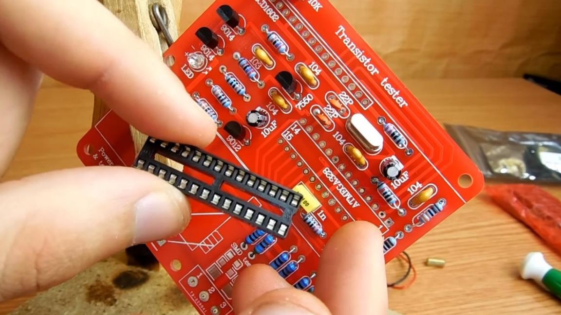
The ATmega328P serves as the main chip, which is already pre-programmed for this tester, but we will install it later.
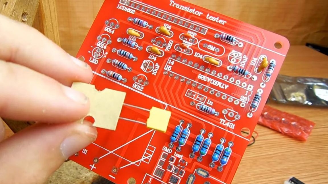
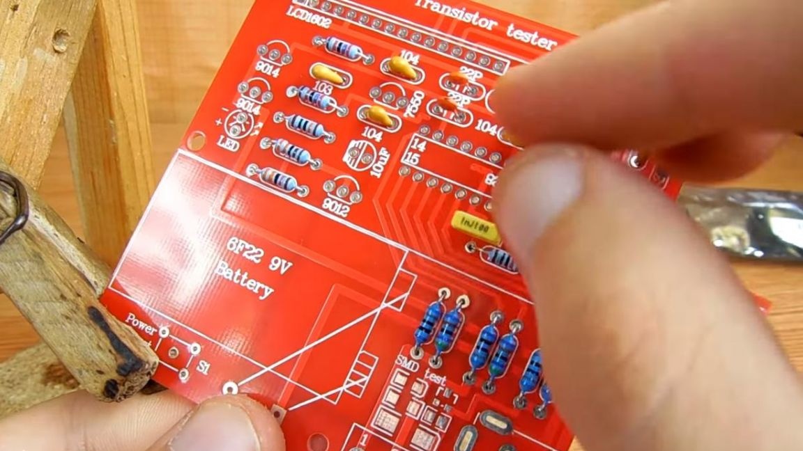
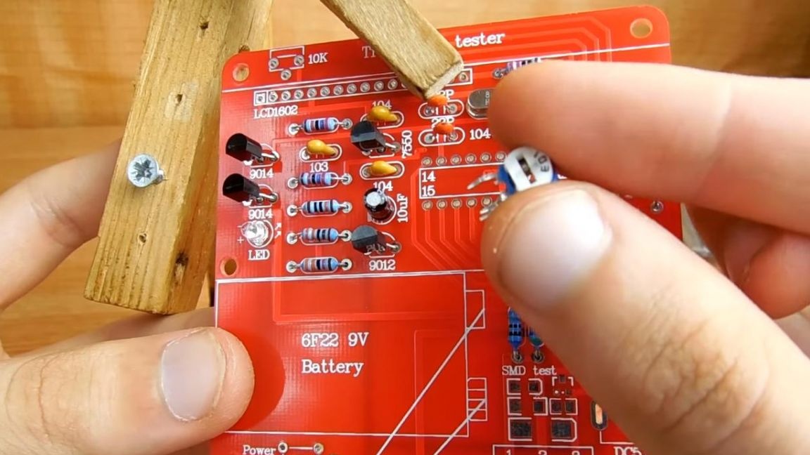
First, insert the resistors, the same values are fastened with a piece of paper.
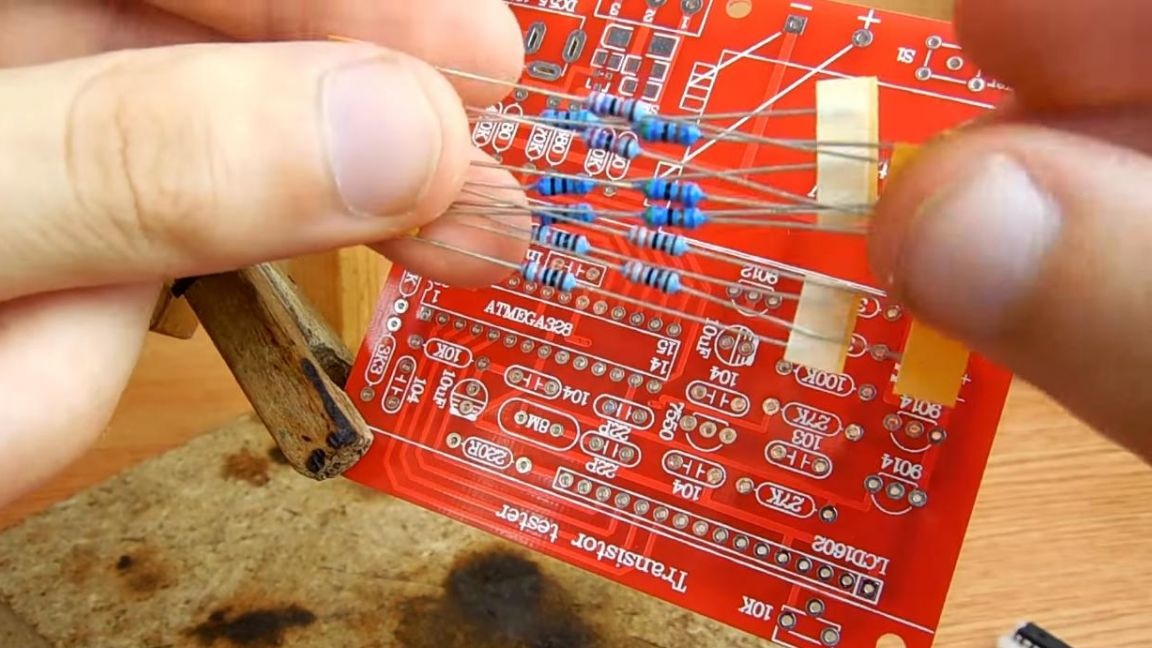
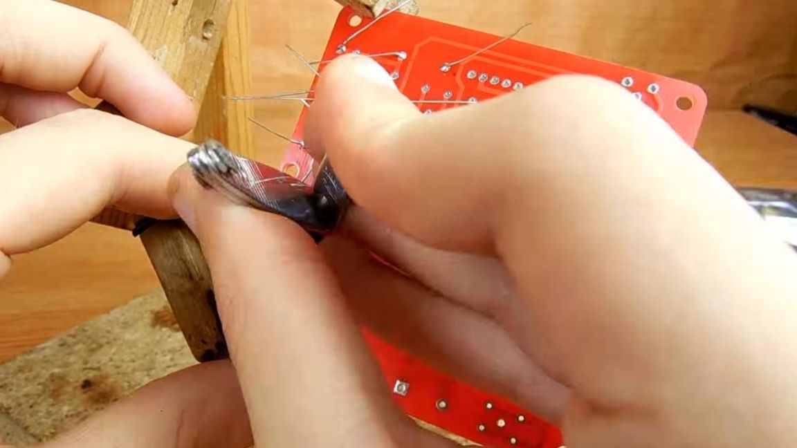
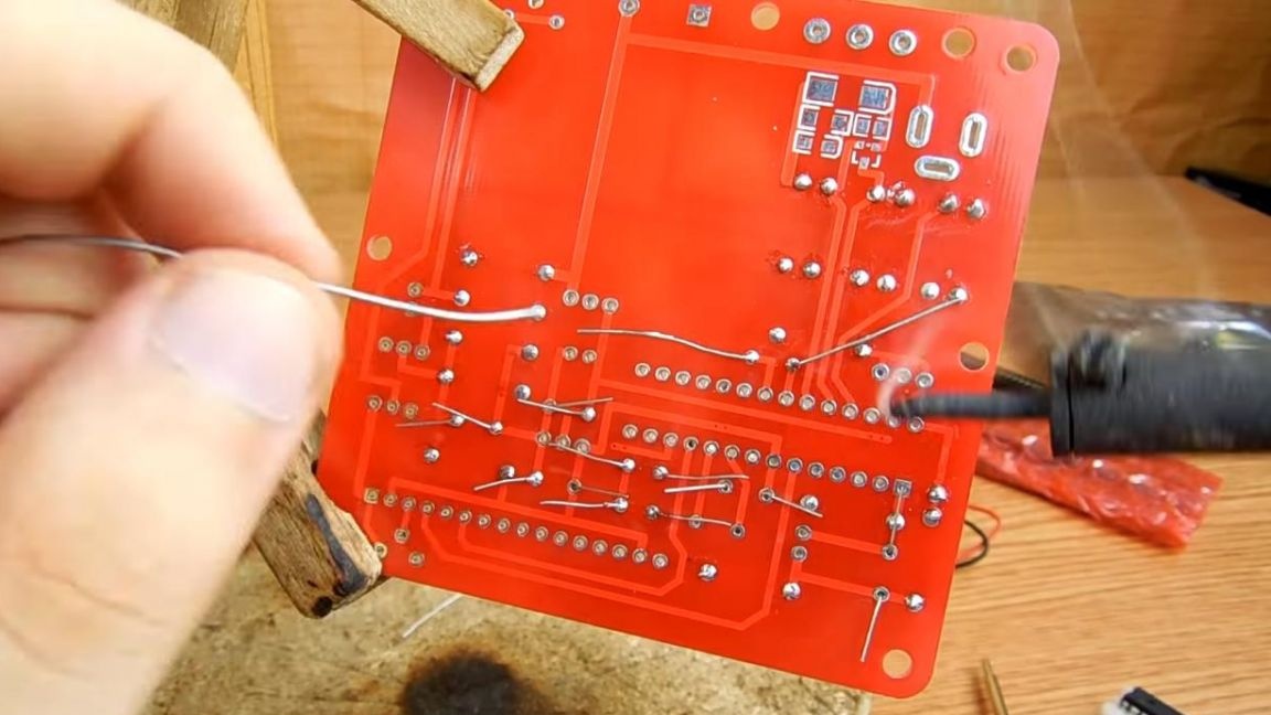
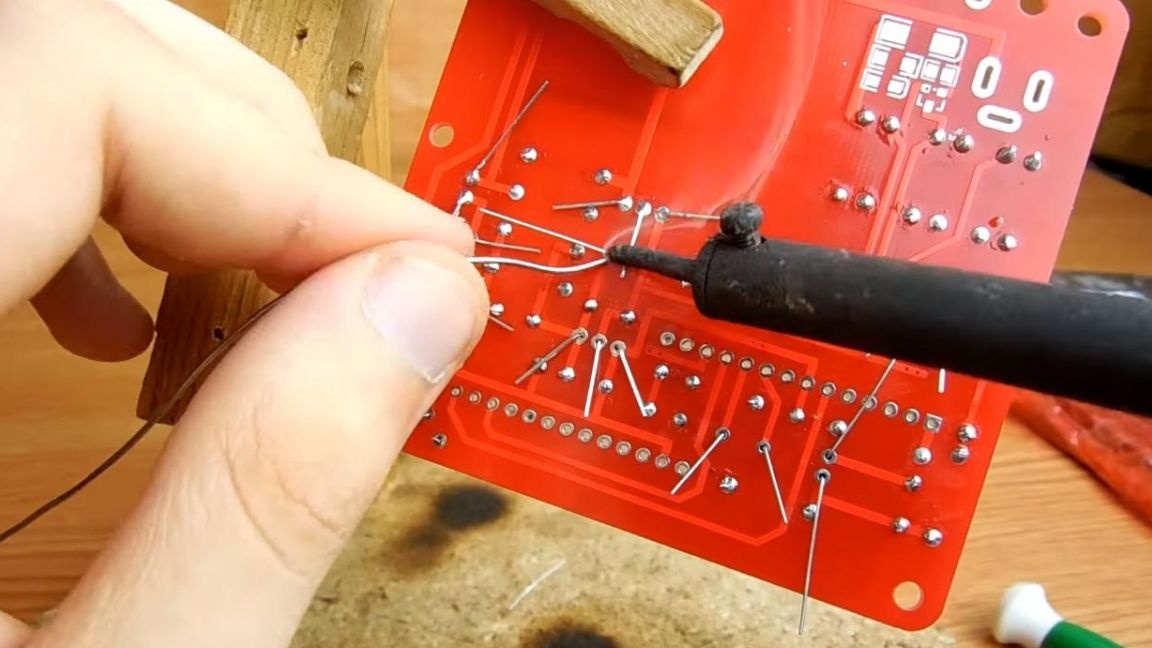
We determine the resistance of the resistors using a multimeter or color coding with a table, then install it on the board according to the ratings indicated on the board. On the back of the board, we bend the conclusions so that when soldering the radio components do not fall out.
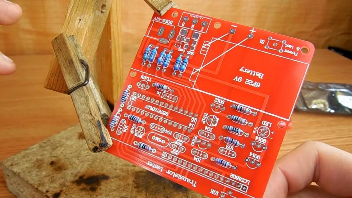
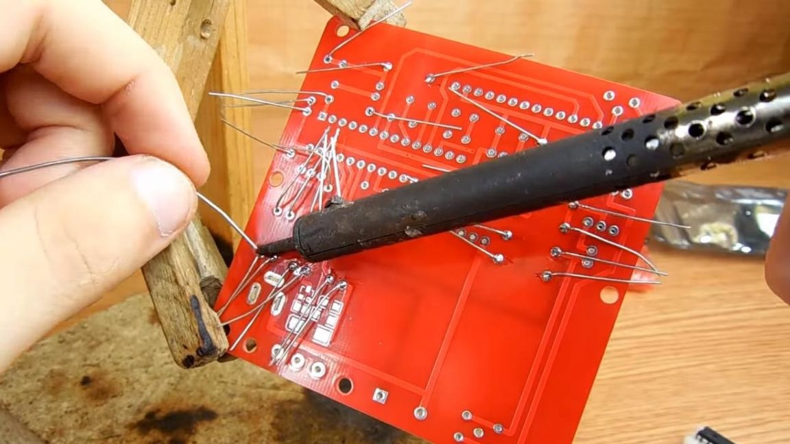
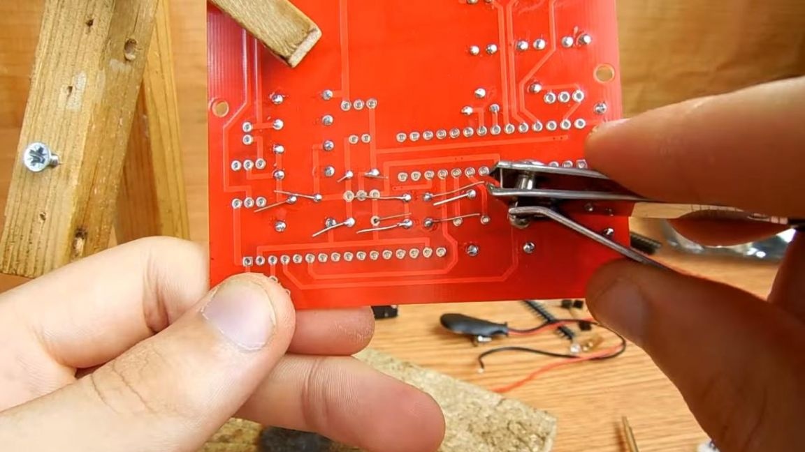
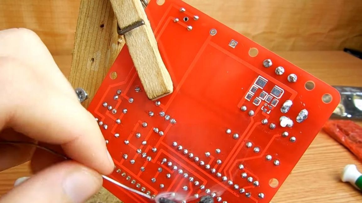
After this, we unfold the board on the other side and solder the resistors, apply a little flux for better soldering, remove the remaining terminals with side cutters or nippers. When removing pins, be careful, as along with this you can tear the track from the board.
Step Two
Next, insert non-polar ceramic capacitors, on the case they are marked with a number, as on the board, for example, 104.
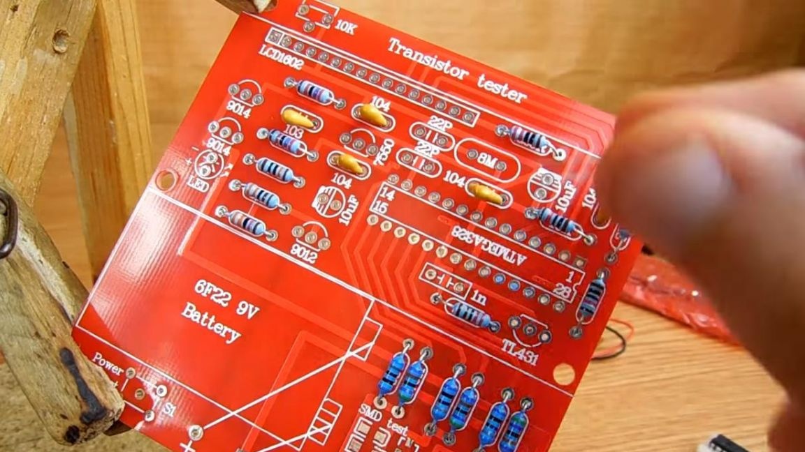
Also in the kit there is one film-shaped capacitor of a rectangular shape, on the board there is a marking for it of the same shape with an inscription of face value 1n.
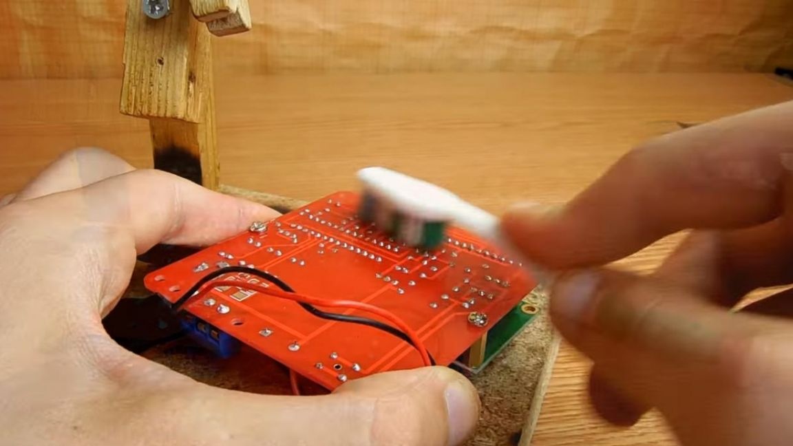
Solder the conclusions on the back side and remove the excess parts of the legs with side cutters.
Step Three
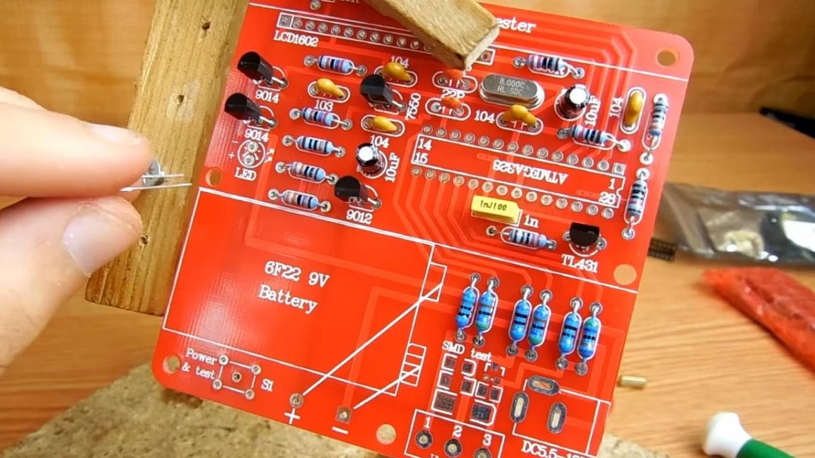
Two electrolytic polar capacitors of the same rating are included, we install them on the board, focusing on the length of the terminals, the long leg is plus, the short one is minus, the plus and minus are marked on the board, also minus is filled in a semicircle.
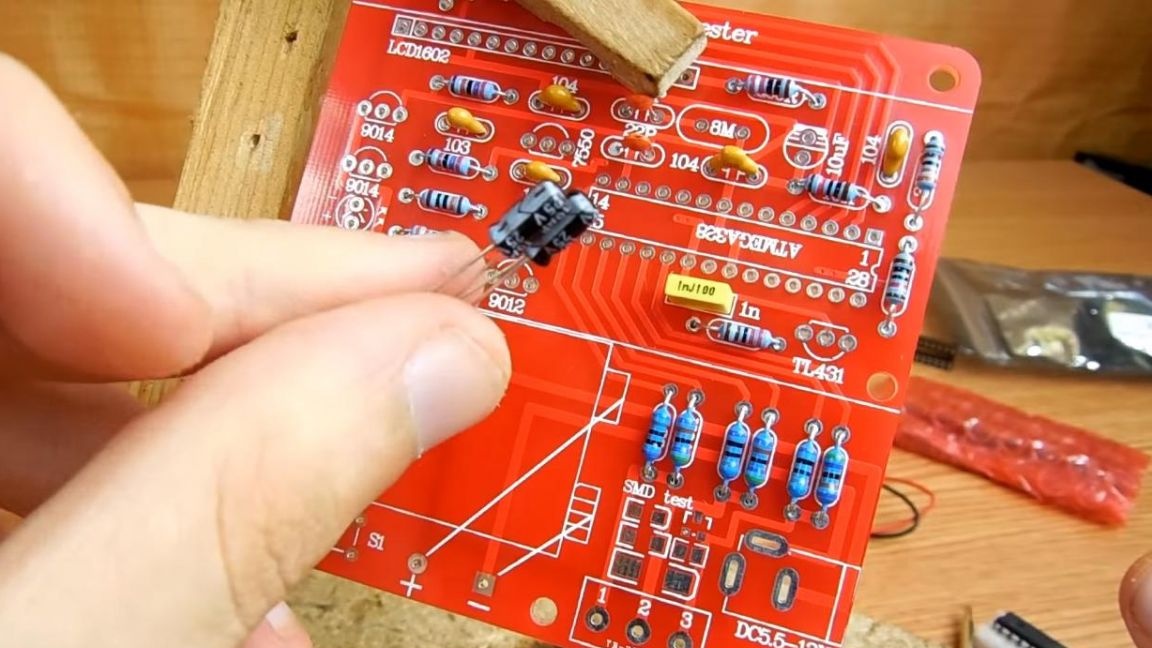
Next, insert the quartz, on the board it is indicated by the marking 8M.
Then we install 4 transistors and a zener diode, we arrange them according to the name and marking on the board in the form of a semicircular case.
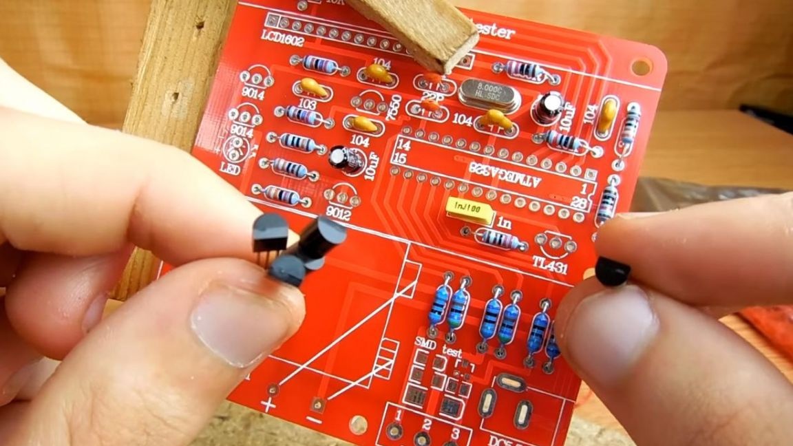
To indicate the operation of the tester, one LED is provided. We insert it into the holes, guided by the length of the legs, the length is plus, the short is minus, the polarity is signed on the board.
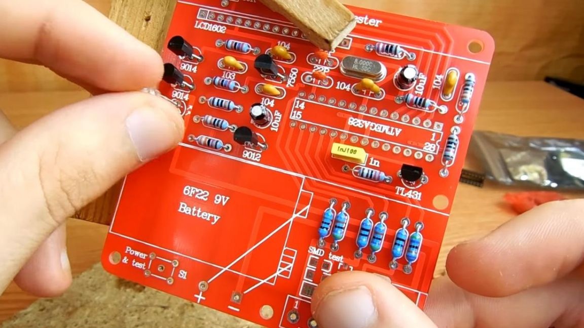
To configure the correct operation of the screen on the board, we install a variable resistor, it has three outputs, it will not work correctly to put it because of their location.
Then we solder the components and, as usual, remove the remnants of the conclusions.
Step Four
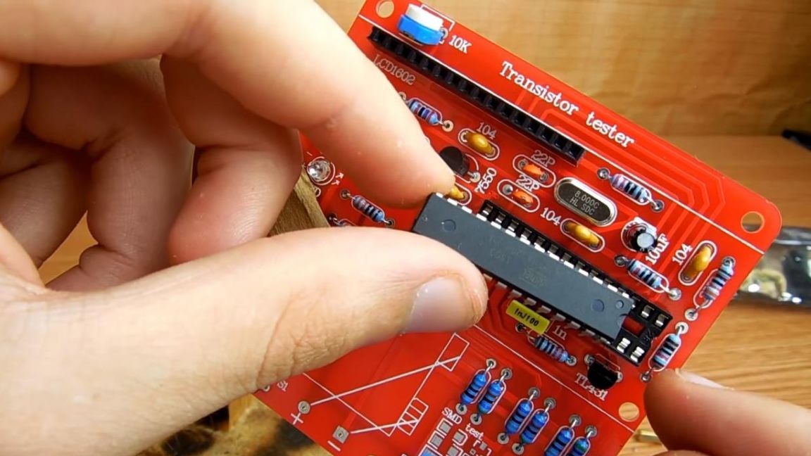
A slot is provided for installing the microcircuit on the board. We install it on the board, focusing on the key on the case and on the board itself in the form of a recess.
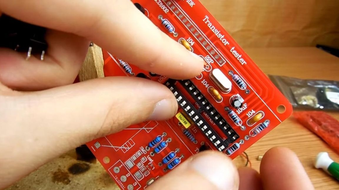
Then we insert the power and test button.
Solder the findings of the parts.
Next, insert the chip into the socket, focusing on the key in the form of a semicircle.
After that, we insert the contacts for connection into the holes on the display board and solder them on the front side.
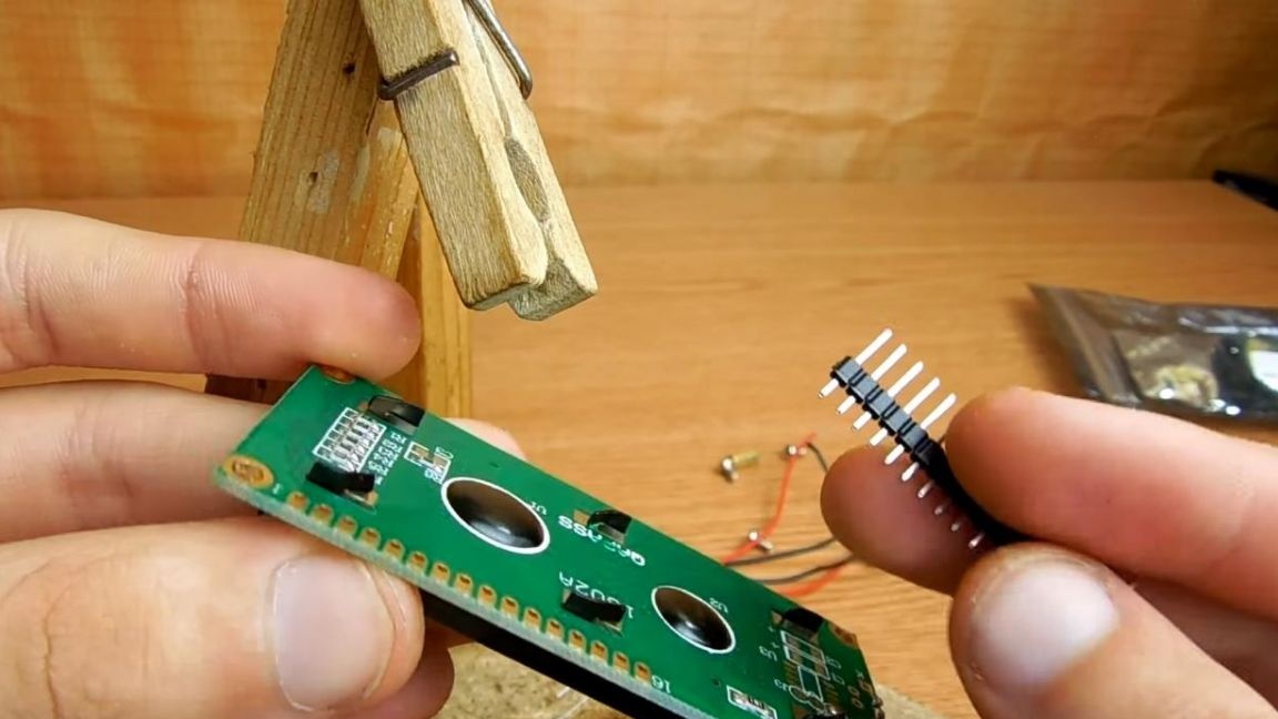
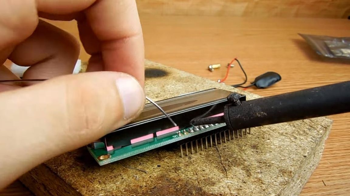
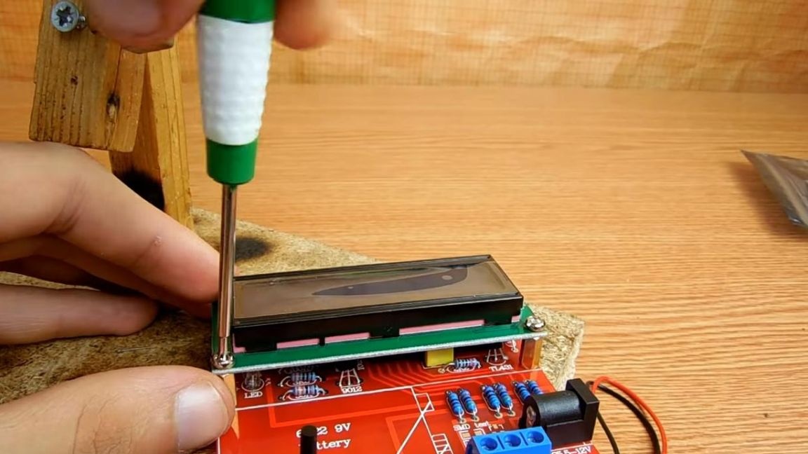
We also solder a plug to the main board to connect power from the crown. Before installing the display, we screw in the threaded bushes, which will serve as a support, for this you will need a Phillips screwdriver, then you can connect the display and screw it to the bushings.
We wash the board off the flux residues with a brush and solvent, and galosh gasoline is also good.
Step Five
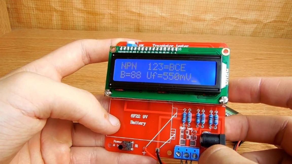
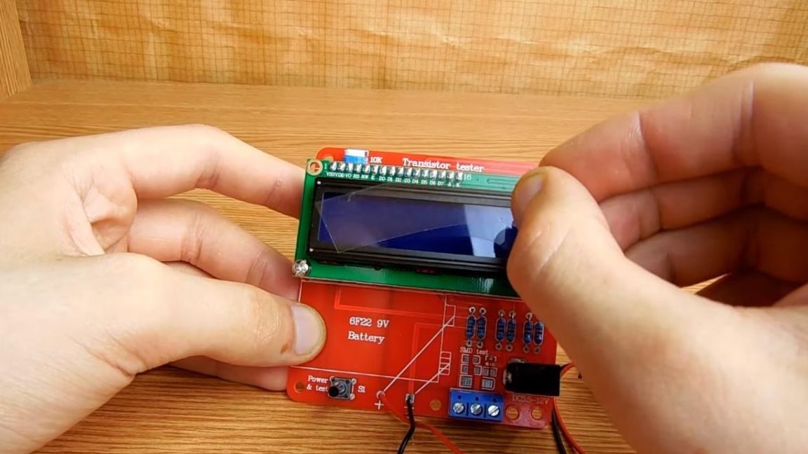
The tester is completely ready, we connect the "krona" battery to it and remove the protective film from the screen.
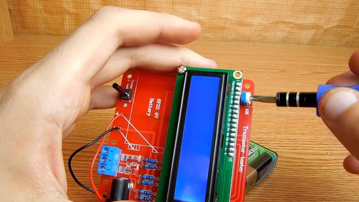
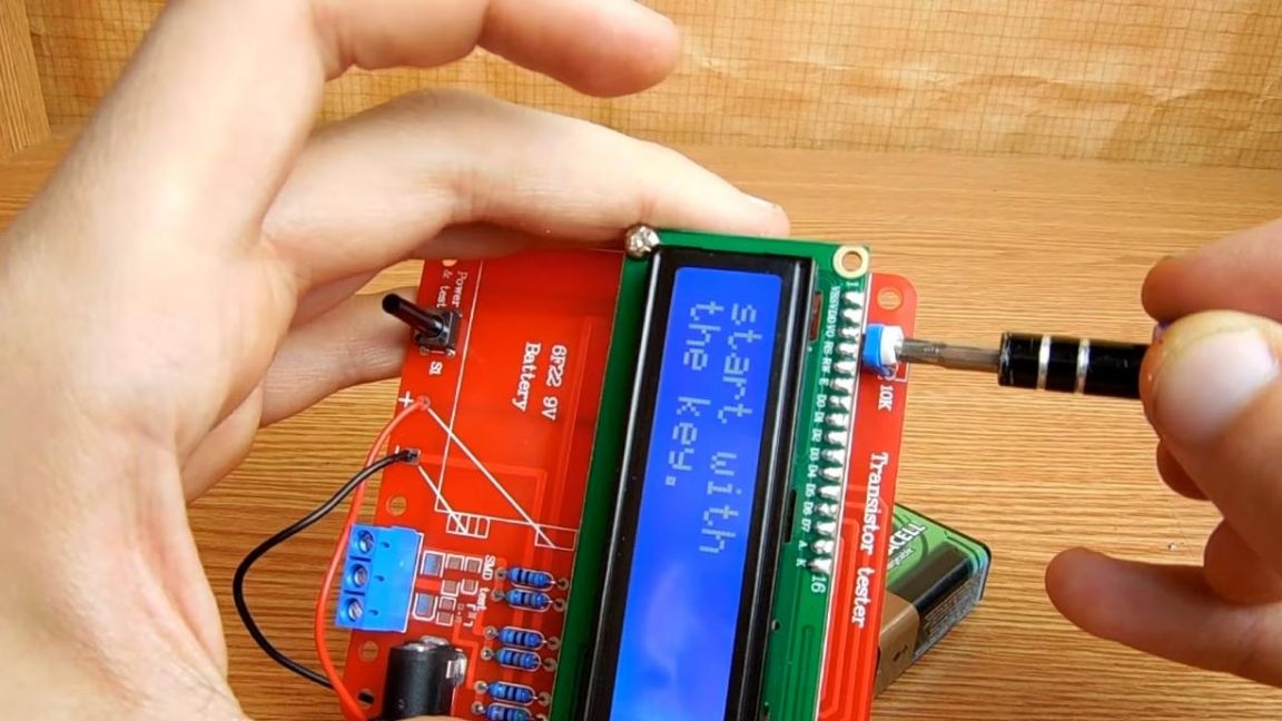
To correctly display the information on the screen with a screwdriver, turn the resistor to the position where the text will be clearly visible.
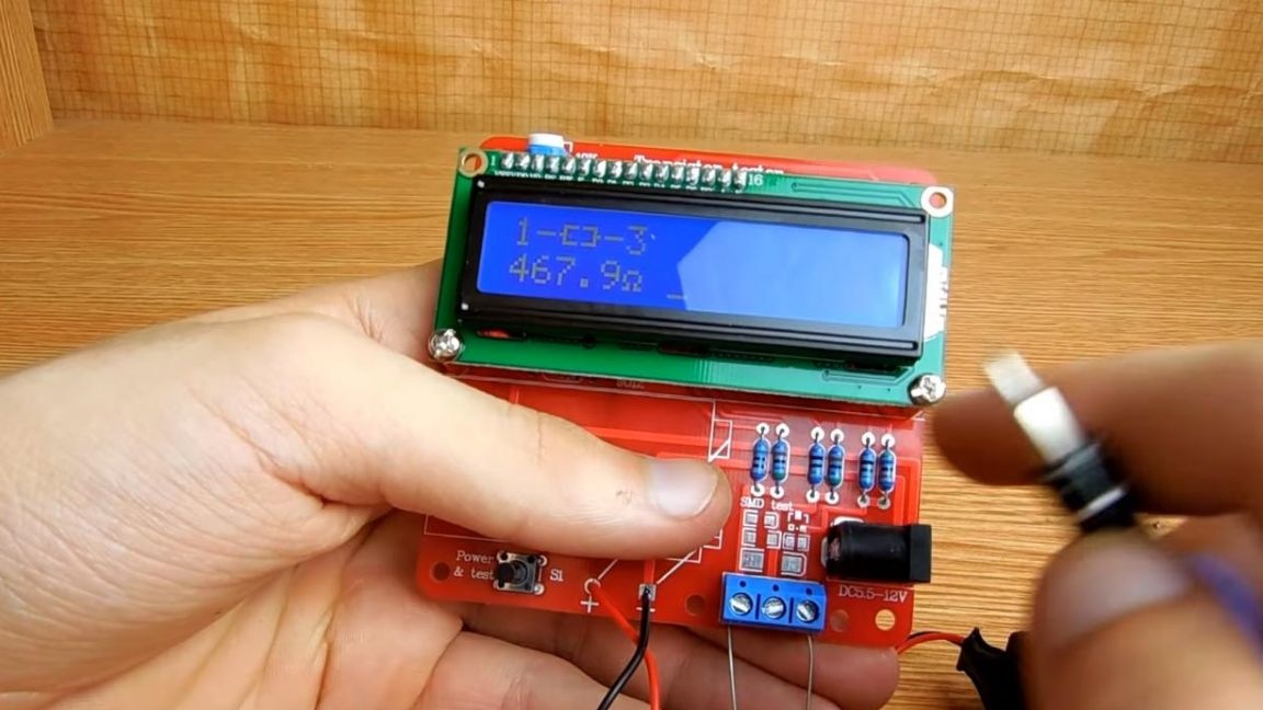
And now you can check the tester on various radio components. Let's start with the transistor, connect its findings to the tester pads and after a while, which takes to measure all the data, we see all the detailed information about the component on the display, and the pinout of the conclusions is also visible.
When a capacitor is connected, information about the capacitance is displayed, thereby one can judge its condition. Also, with the help of this tester, you can find out the resistance of the resistor, which is very convenient in the assembly of other kit kits.
This tester of transistors and other radio components will be useful for both beginners and those who have long been friends with radio electronics.
That's all for me, thank you all for your attention and creative success.