
Hello to all lovers homemade. In this article I will tell you how to make a preamplifier with the NE5532 tone block do it yourself, in the assembly of which the kit kit will help, a link to it will be at the end of the article. This kit kit will be useful to those who want to try their hand at assembling radio constructors and gain experience, as well as for assembling a full-fledged amplifier. With this preamp preamp, you can adjust the low, mid and high frequencies, as well as amplify the input signal.
Before reading the article, I suggest watching a video with a detailed process of assembling a kit kit and testing.
In order to make a pre-amplifier with the NE5532 tone block yourself, you will need:
* Kit
* Soldering iron, solder, flux
* Side cutters
* Speakers
* Device for soldering "third hand"
* Multimeter or tester
* Sound amplifier and bipolar power to test
Step one.
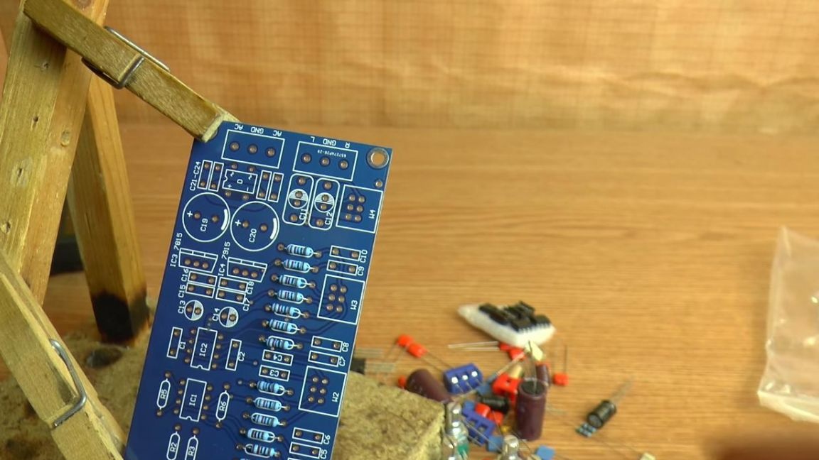
First, let's deal with the components that come with the kit.
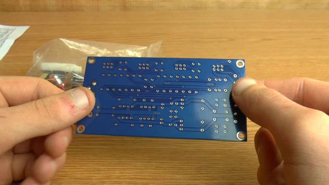
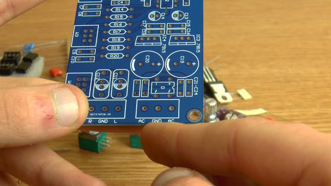
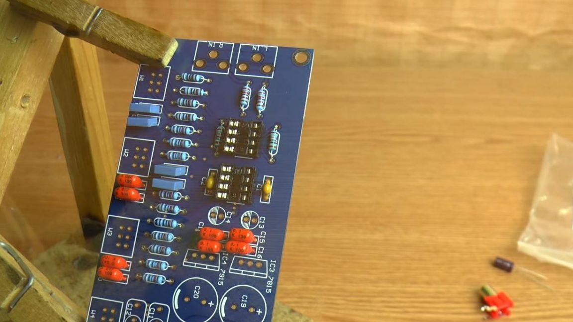
The kit kit comes with a double-sided board with metallized contacts, the quality is at a high level.
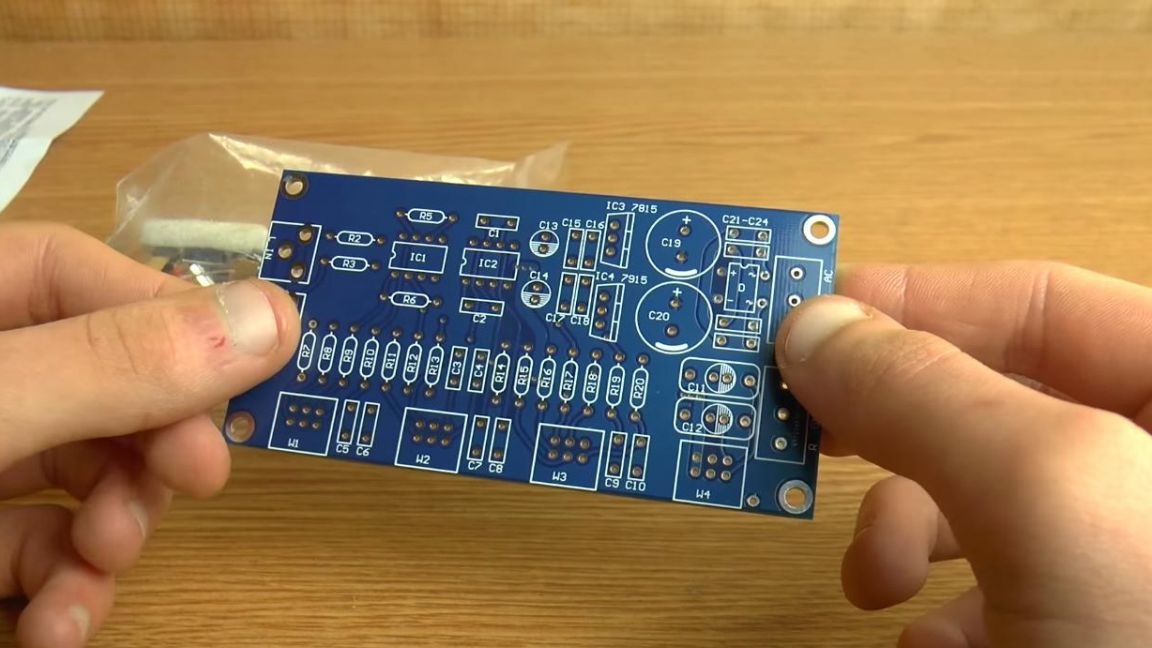
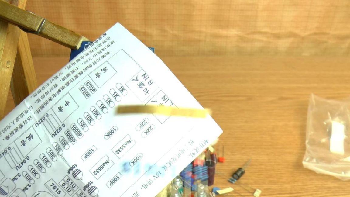
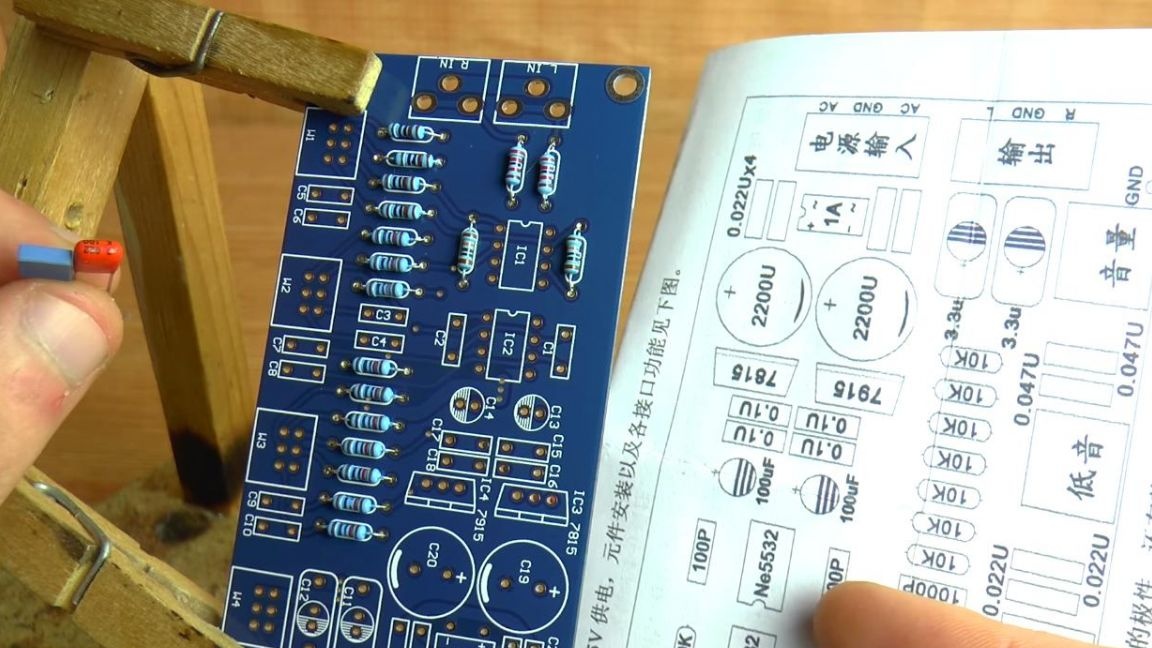
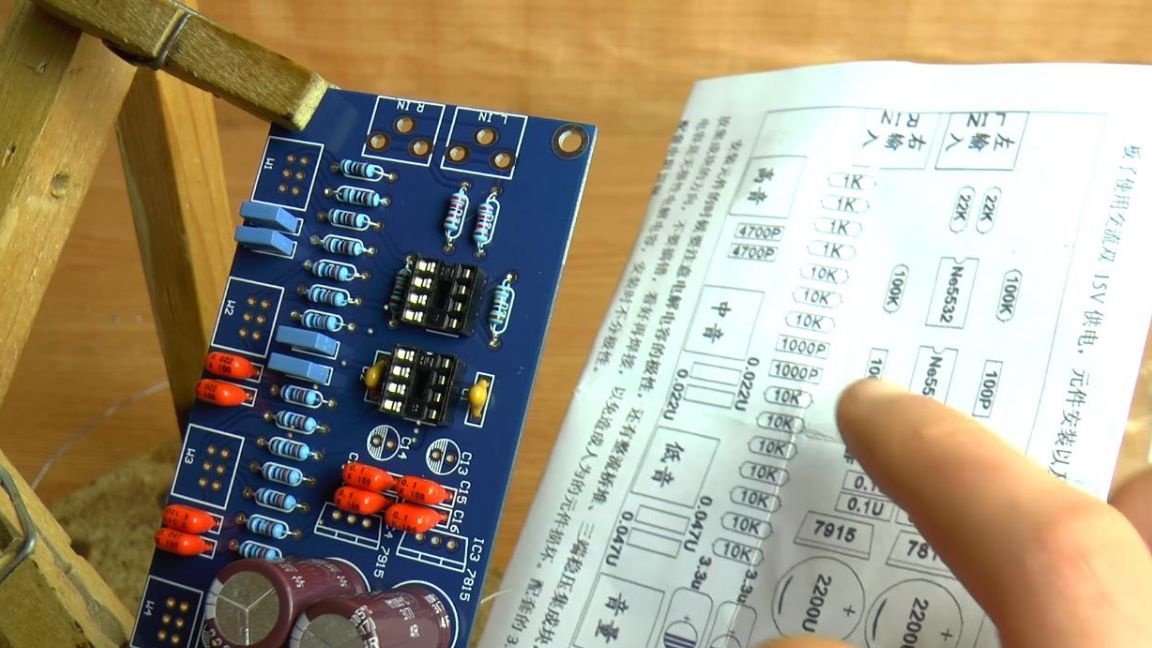
Not all the ratings are signed on the board itself, so the instructions were also put in the kit.
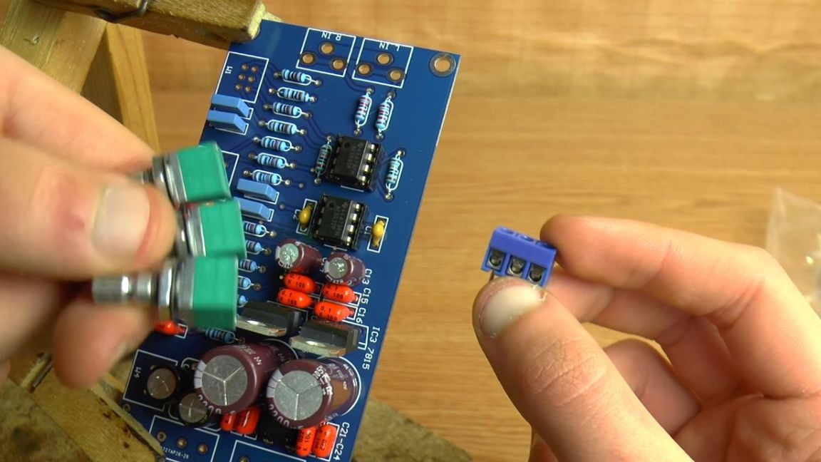
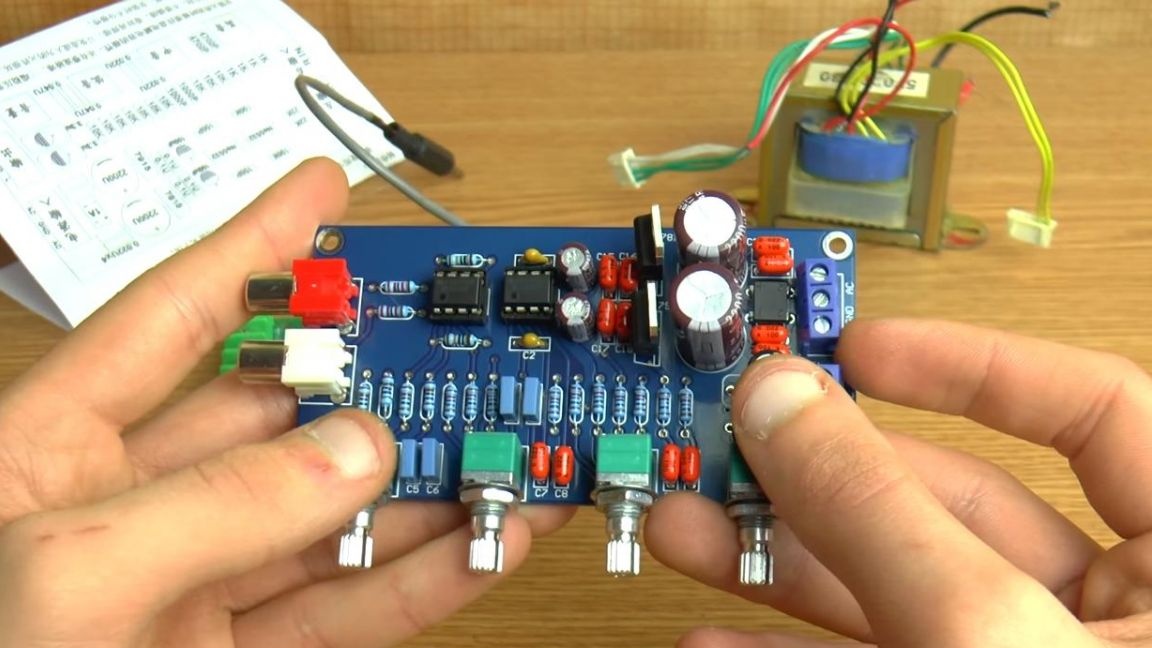
To adjust the sound level, as well as low, medium and high frequencies, four two-channel variable resistors are provided, the nominal value of each 50 kOhm.
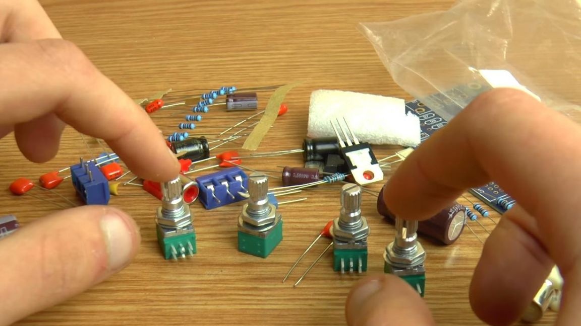
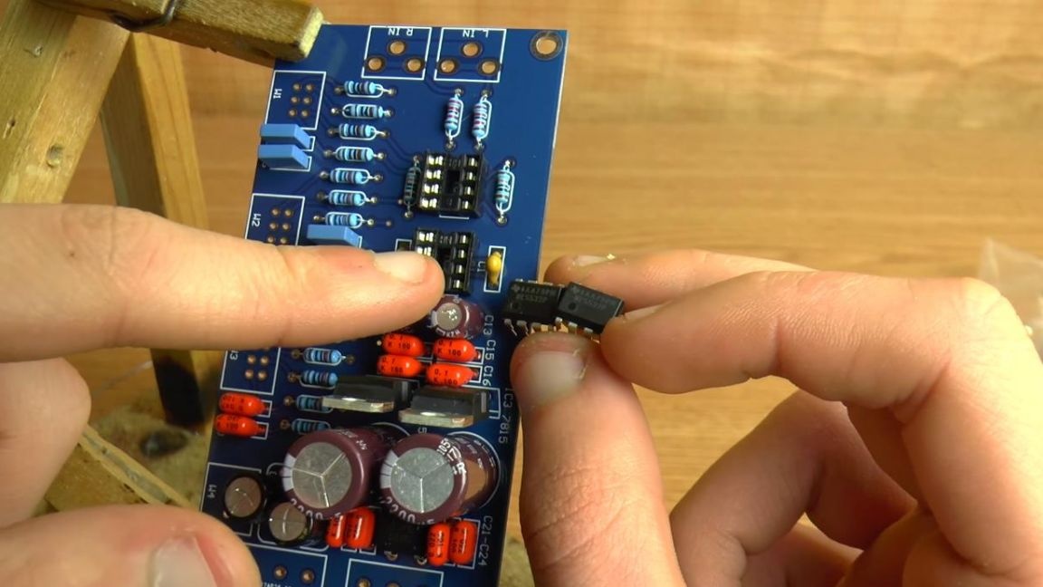
The main chip in this set is the NE5532 low-power amplifier, since this option has stereo, there are two of them in the set, there are also special sockets for mounting them on the board.
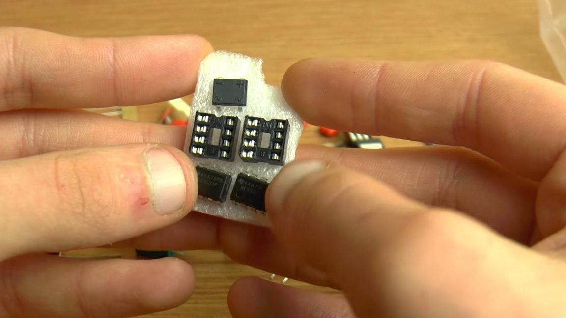
The ready kit kit needs to be powered from bipolar power, a diode bridge is provided from reverse polarity.
Step Two
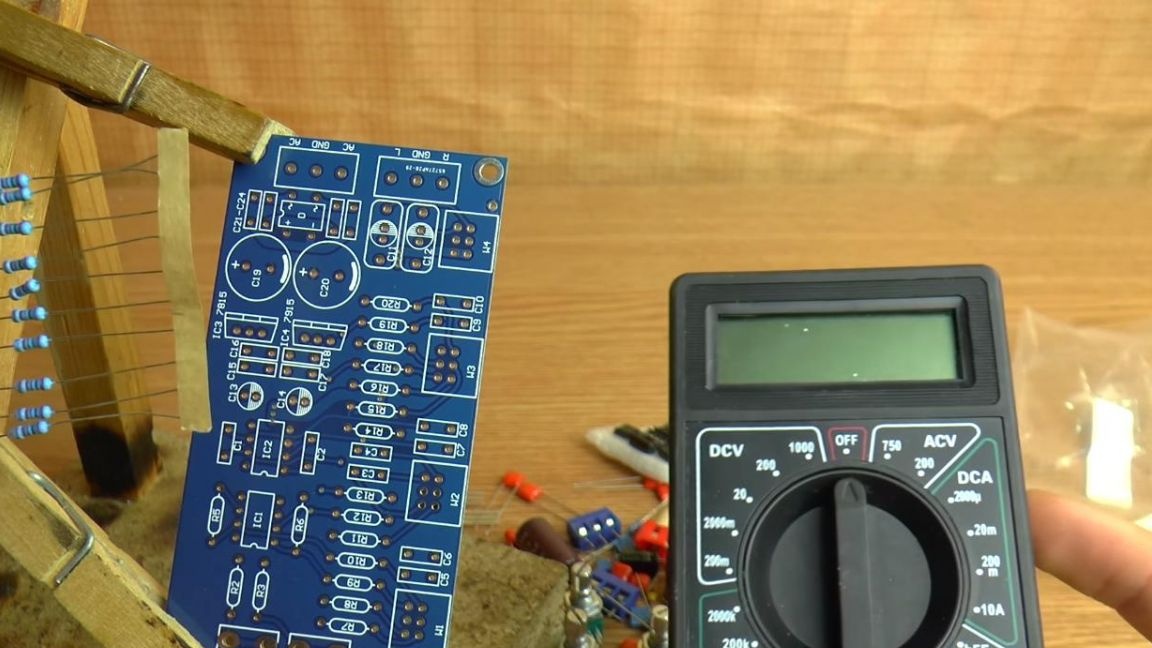
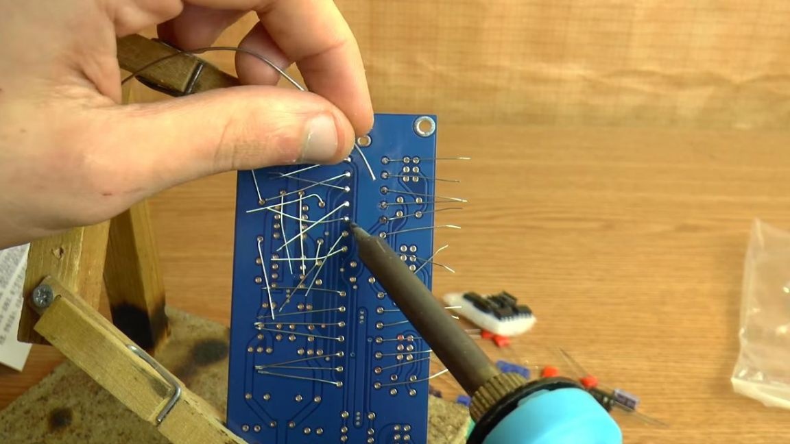
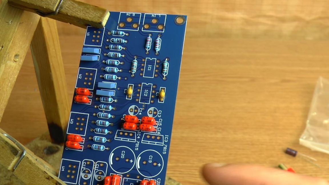
We pass to the assembly itself. To begin with, we install the board in the "third hand" soldering device and insert the resistors according to the ratings.
You can determine the resistance in several ways, using a multimeter, a tester, as well as color coding and a table. The first method is the most convenient and fast, but the others are also quite working, but require a bit more time, so the presence of a multimeter is not a mandatory item.
The resistor values are not indicated on the board, so we use the instructions.
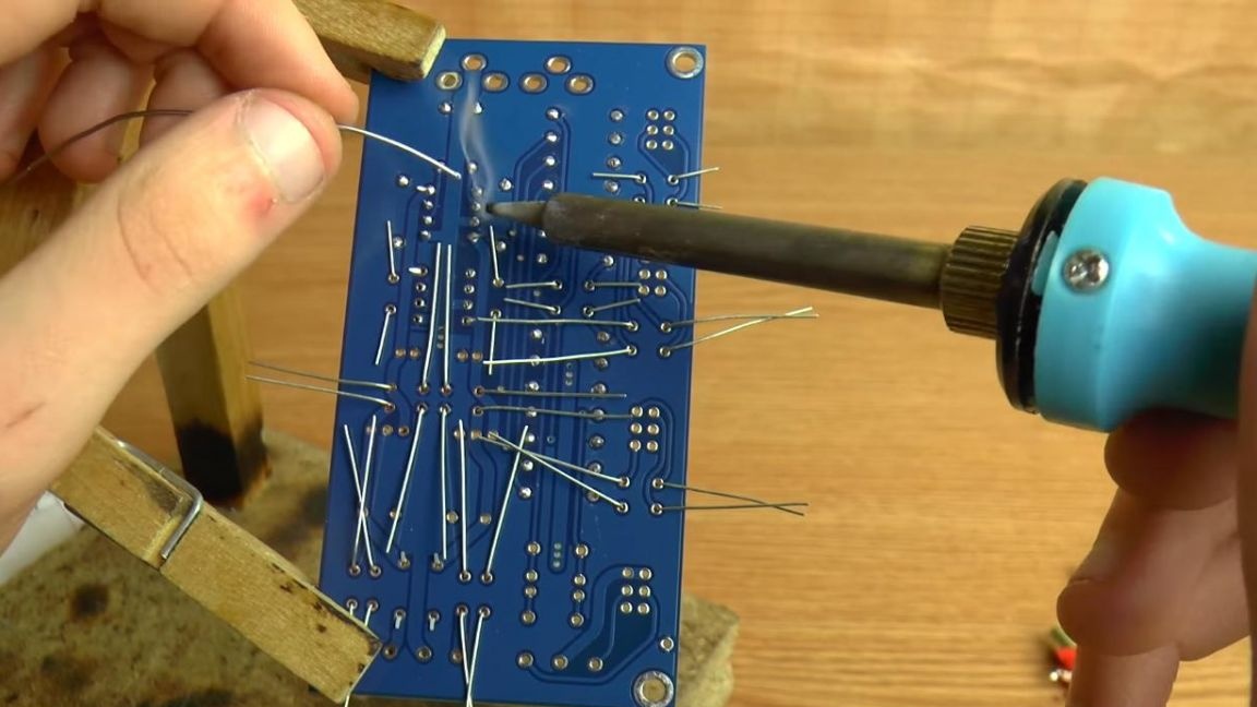
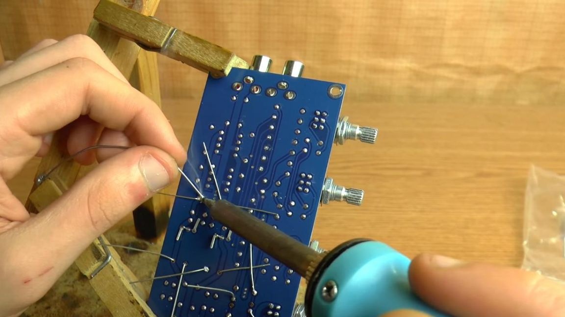
In order to prevent the resistors from falling out when soldering, we bend the legs on the back of the board. Next, solder the conclusions to the board using a soldering iron and solder, for better soldering, apply flux.
Step Three
After installing the resistors, we turn to ceramic non-polar capacitors.
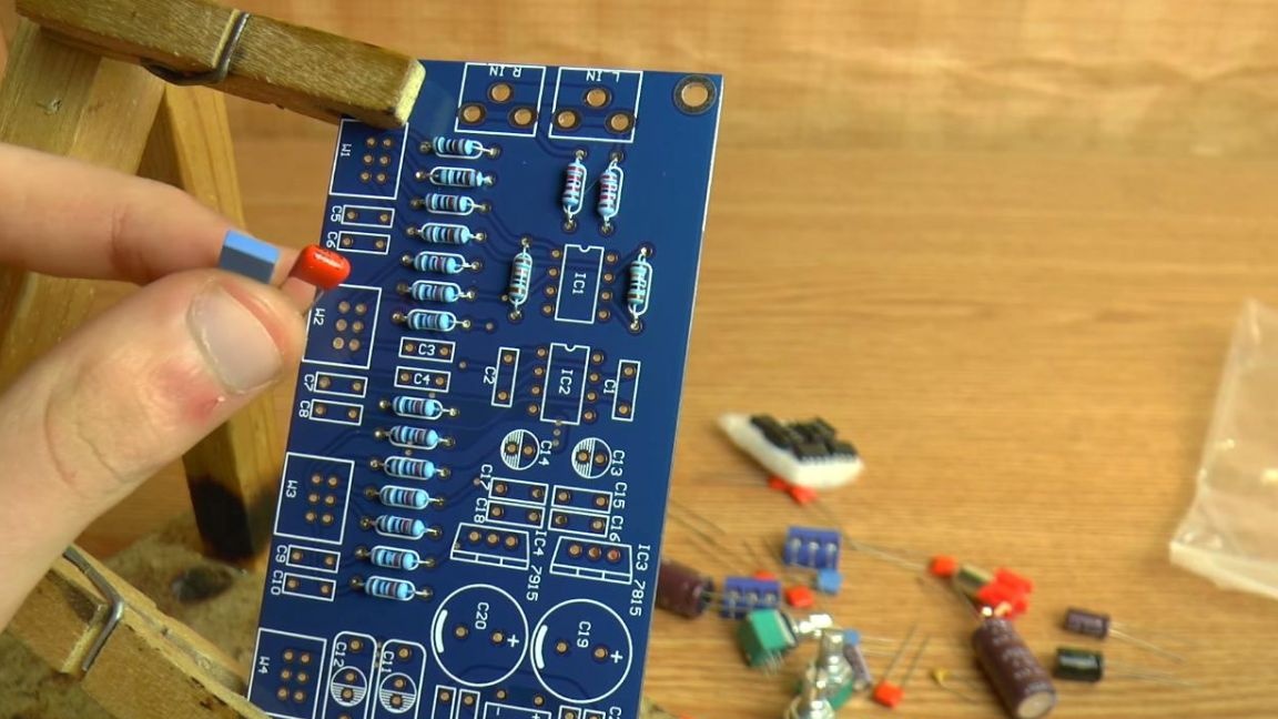
We insert them on the board according to the digital marking on the case, the capacitor number is signed on the board, so we follow the instructions.
The board provides protection against reverse polarity as a diode bridge, we set it, observing the polarity, it is indicated on the case and on the board itself.
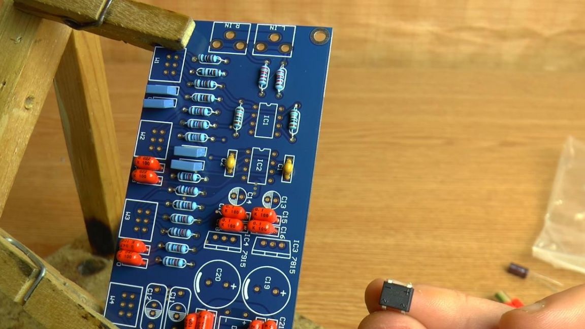
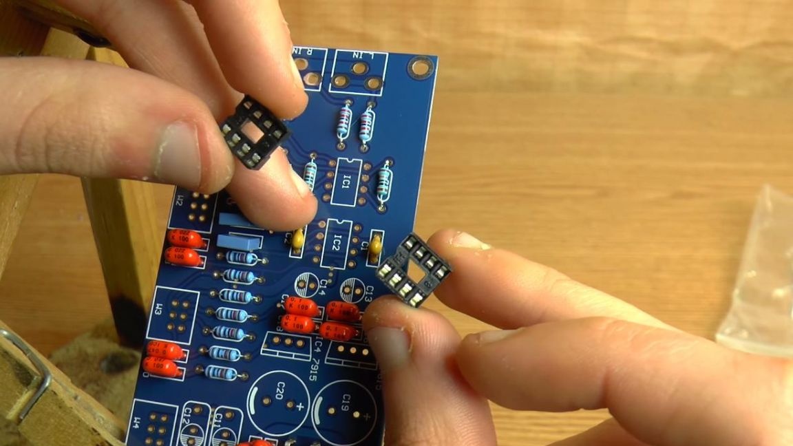
Next, we put the sockets for installing microcircuits, they have a special key in the form of a recess, which we combine with the key on the board.
After that, solder the conclusions on the back of the board.
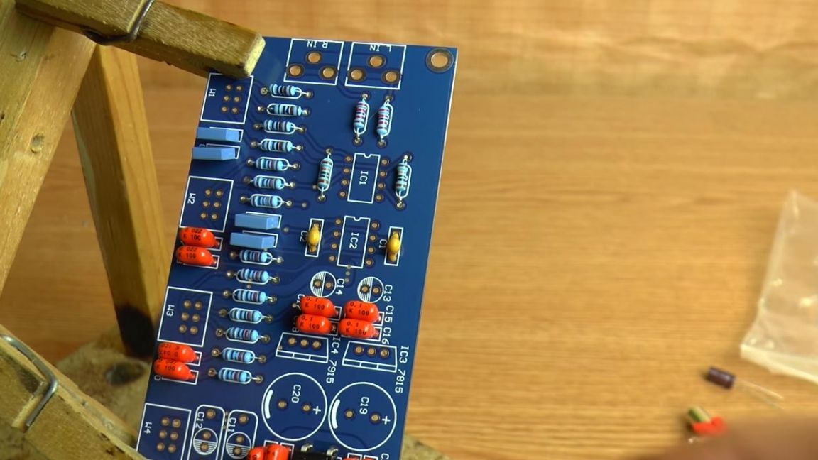
Step Four
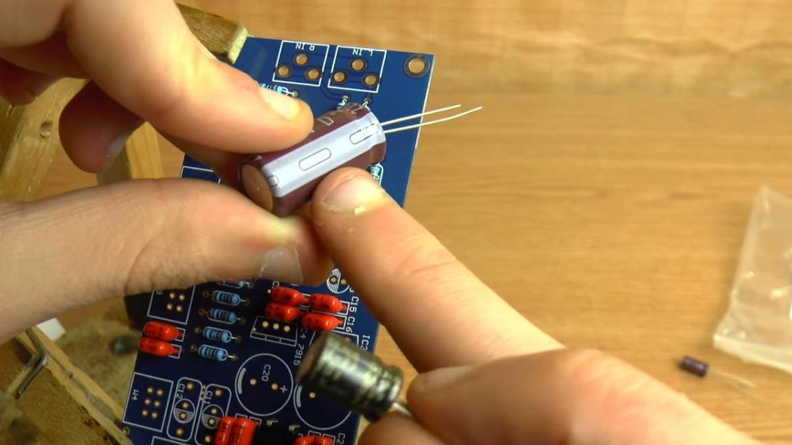
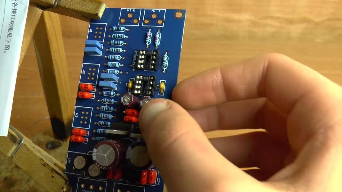
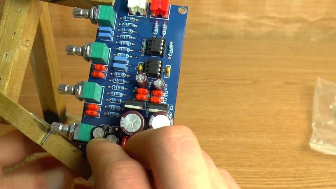
Now, according to the values indicated in the instructions, we insert the polar electrolytic capacitors in their places, on their case the strip indicates the negative output, on the board the minus is indicated by a white line, in the case of small capacitors the minus on the board is indicated by a filled semicircle.
Next, we insert the stabilizers, the board is marked in the form of a case, we are guided by it and by name, since they differ from each other.
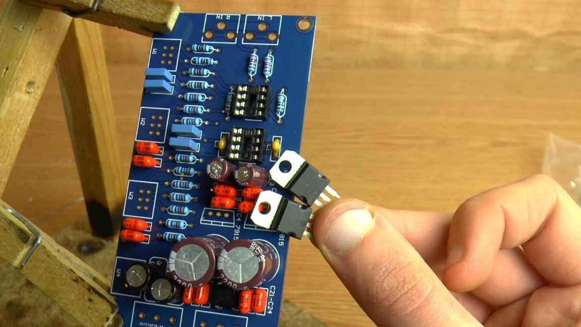
We place microcircuits in special sockets, we place the key on the case in the form of a dot on the same side as the notch on the board.
Step Five
There is very little left until the assembly is complete. To connect the power, insert the connectors.
Next, we put the nests under the tulips, as well as variable resistors.
After that, we solder everything thoroughly and remove the extra part of the conclusions with the help of side cutters. When removing the terminals with side cutters, be careful, along with the leg, you can accidentally tear off the board track.
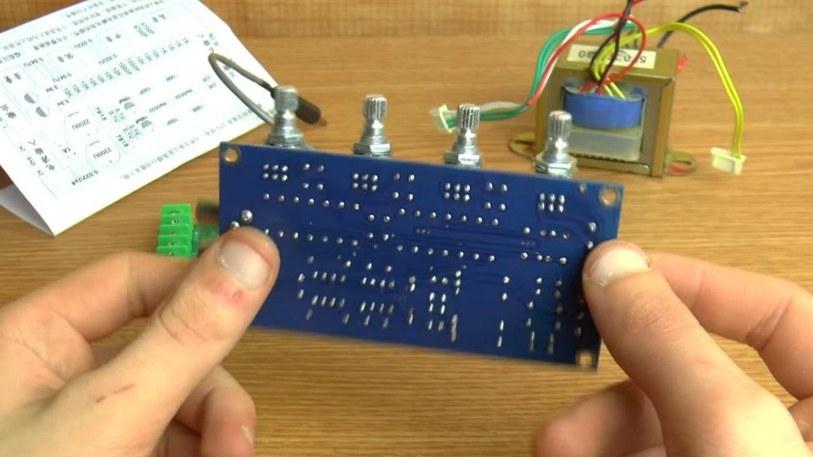
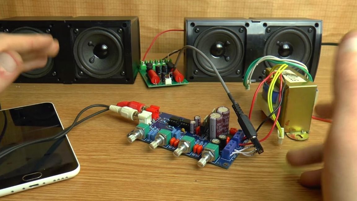
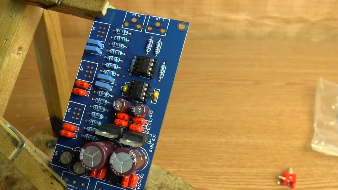
On this, the preamplifier with the timbral block is completely ready, which means that it can be checked in operation.
We connect the bipolar power supply to the terminals, according to the polarity. Then we connect the phone to the input of the preamplifier, and already connect the sound amplifier to its output.
The result is a good pre-amplifier with a timbral block, which has the ability to adjust low, medium, high frequencies, as well as the volume level. Such a set will be useful to those who want to assemble their homemade acoustics or an amplifier with full sound control.
That's all for me, thank you all for your attention and creative success.