
Hello to all lovers homemade. In this article I will tell you how to make a spectrum analyzer do it yourself, in the assembly of which the kit kit will help, you can order it by the link at the end of the article. This kit kit will be assembled on LEDs and is more suitable for those who want to try their hand at radio electronics.
Before you read the article, I suggest watching a video that details the process of assembling the kit and its testing.
In order to make a spectrum analyzer in a transparent case with your own hands, you will need:
* Soldering iron with a thin tip, flux, solder
* Power supply with USB port or power bank
* Phone to check the device
Step one.
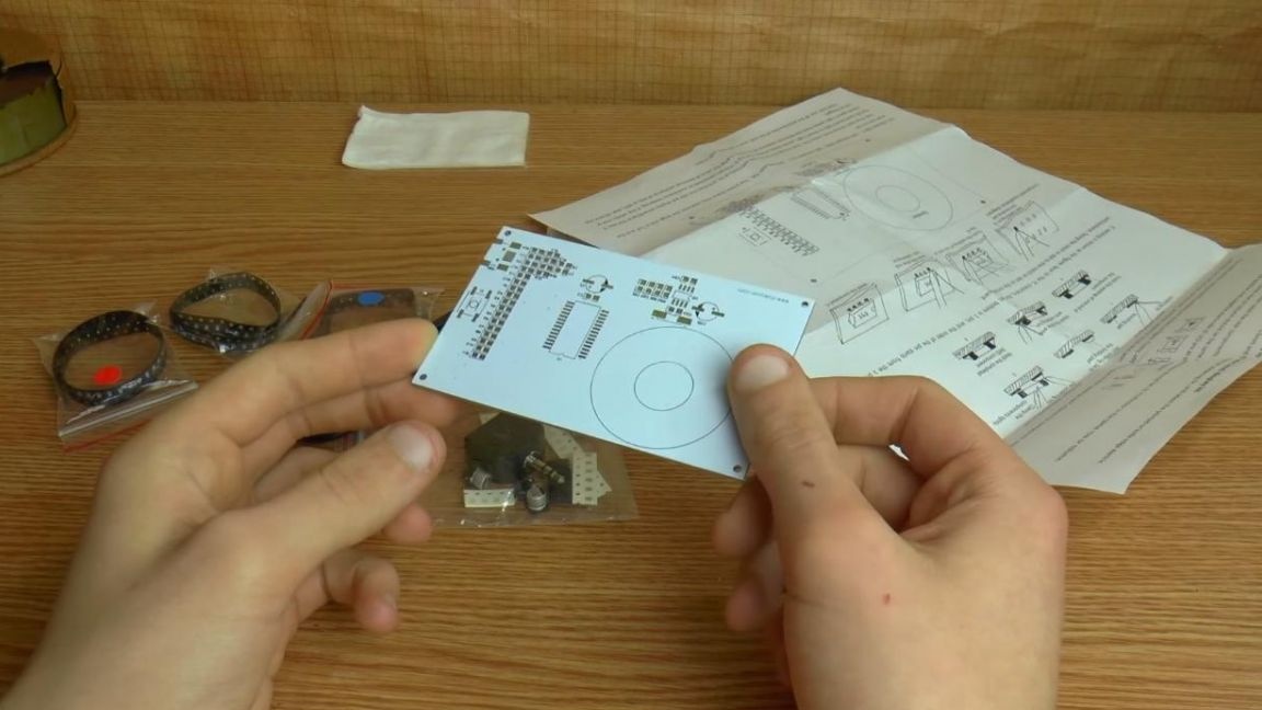
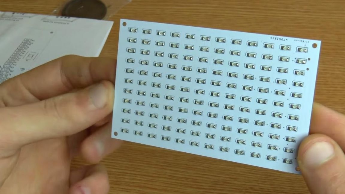
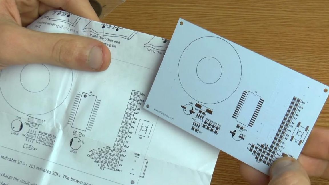
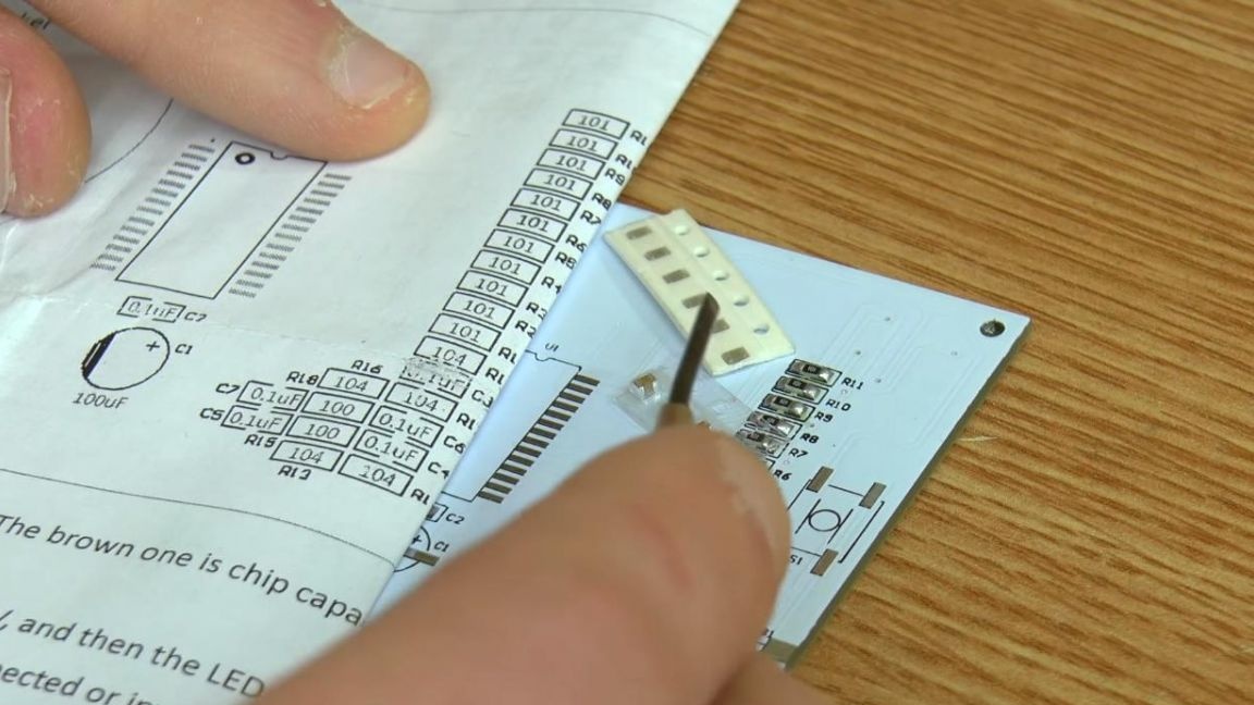
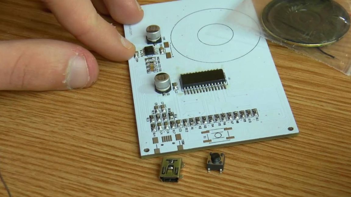
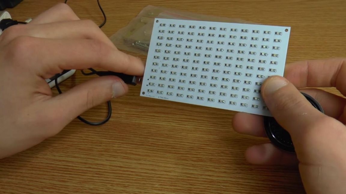
First, consider the kit kit. The printed circuit board is made quite high quality and has contacts for SMD components on both sides, so in this case it will be more convenient to work with a soldering iron with a thin sting.
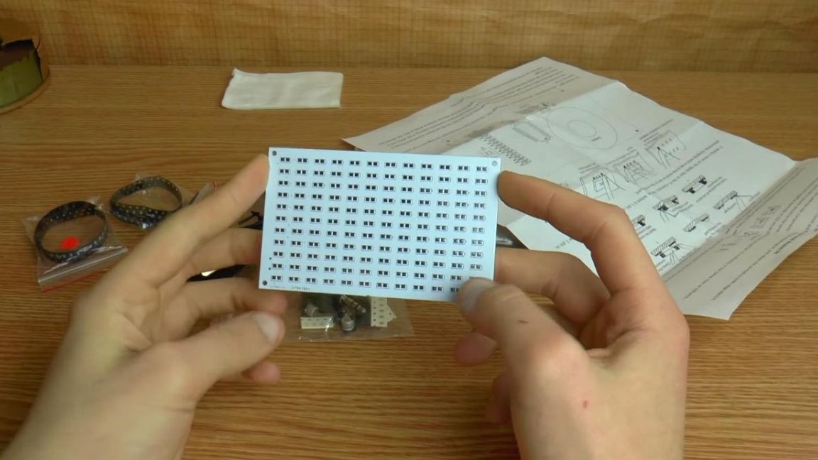
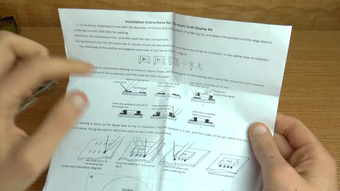
On the board, the values of resistors and other radio components are not signed, so there is an instruction with all the data for assembly in the kit.
Step Two
We proceed directly to the assembly.
First of all, we solder the SMD LEDs. The instructions indicate how to solder them, and also indicated where is the plus and minus of the LED. On the board, the polarity is indicated differently, on the rounded side there is a negative contact, and on the right - a positive contact.
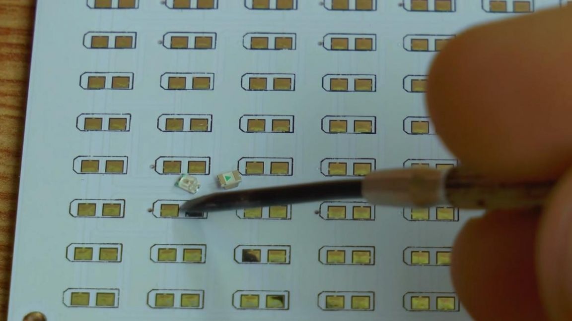
Also, for ease of installation on the LED, one contact is marked green, this is a minus. To check the LED, you can use the dialing mode on the multimeter.
We apply flux to the board contact and add solder, after which we put an LED on the tinned contact and solder one of the legs, then the second. For such purposes, it is best to take a soldering iron with a thin tip, since the contacts of the radio components are very small, and when working with a large soldering iron there is a chance of overheating the LED, which can damage it.
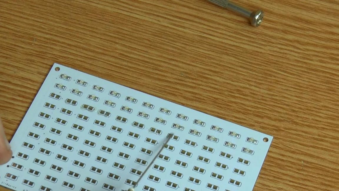
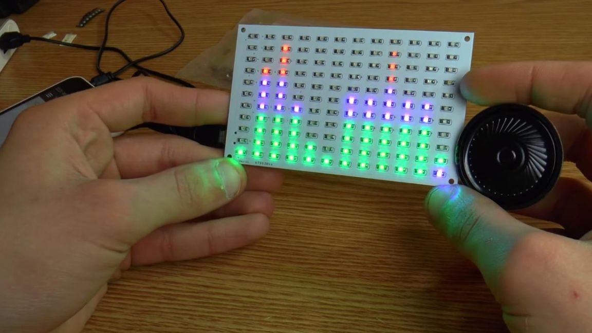
We try to arrange the LEDs as evenly as possible, the result will depend on this. The location of the LEDs is red above, blue in the middle and green at the very bottom. Observing the polarity, we install all the LEDs, before this we apply a flux for better soldering. All LEDs are soldered, go to the other elements on the back of the board.
Step Three
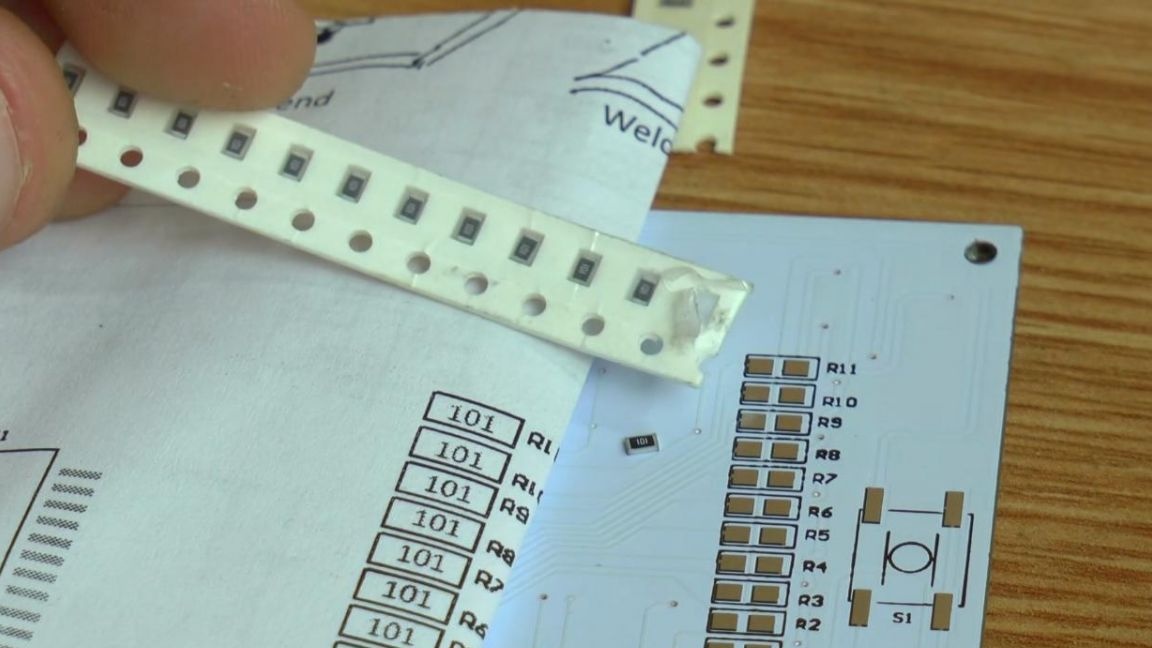
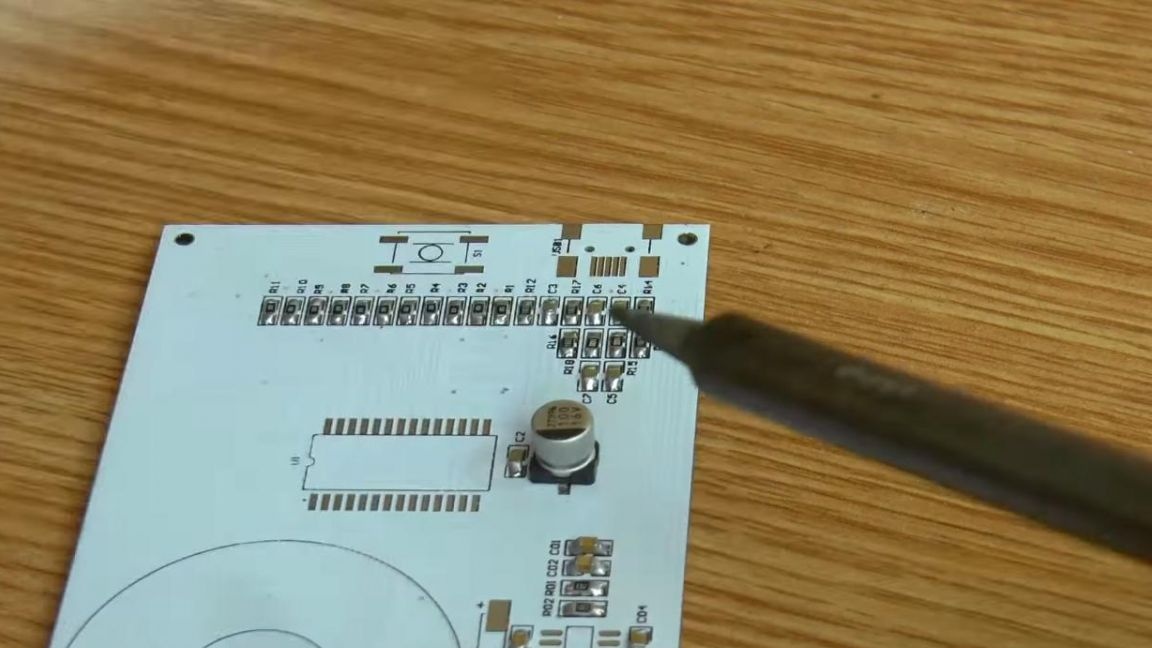
On the reverse side of the board, first solder the resistors. Their values are not indicated on the board, so we will use the instructions.
A digital marking is indicated on the case of the resistors, everything is simple here, the first two digits indicate a numerical value, and the third one a factor, that is, the resistor number 103 has a resistance of 10 * 10 to the 3rd degree, which means 10 kOhm. If four numbers are indicated on the case, then the first three is a numerical value, and the fourth factor, so a resistor with the marking 104 is the same as 1003.
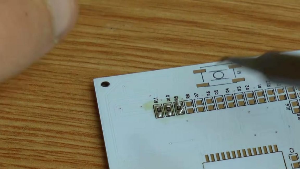
We apply flux and solder the resistors according to the ratings.
Also in the kit there are two ratings of non-polar ceramic capacitors, those that have a larger capacity of 1 microfarad, which is less than 0.1 microfarad, are also indicated in the instructions.
Solder them similarly to resistors.
Step Four
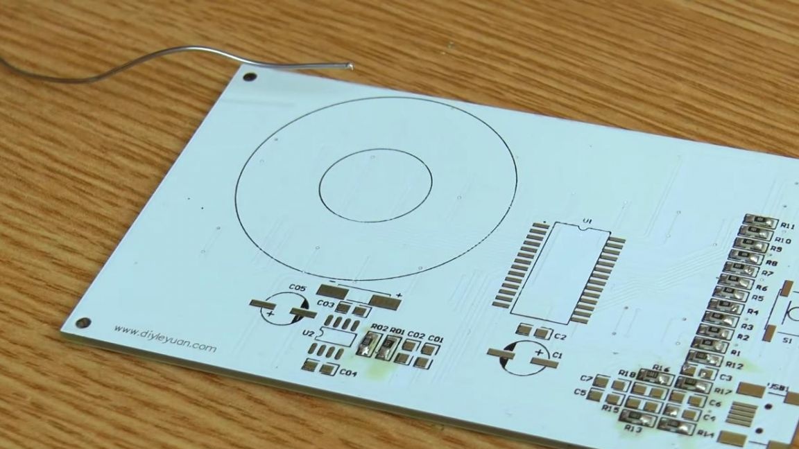
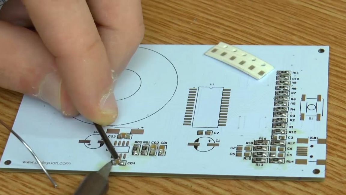
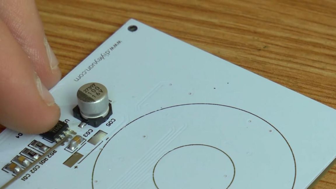
We solder the polar electrolytic capacitors, there are only two of them and the polarity is indicated on the case, minus is indicated by a filled semicircle, as well as on the board.
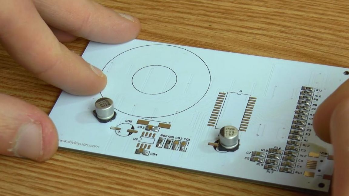
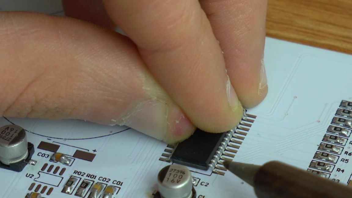
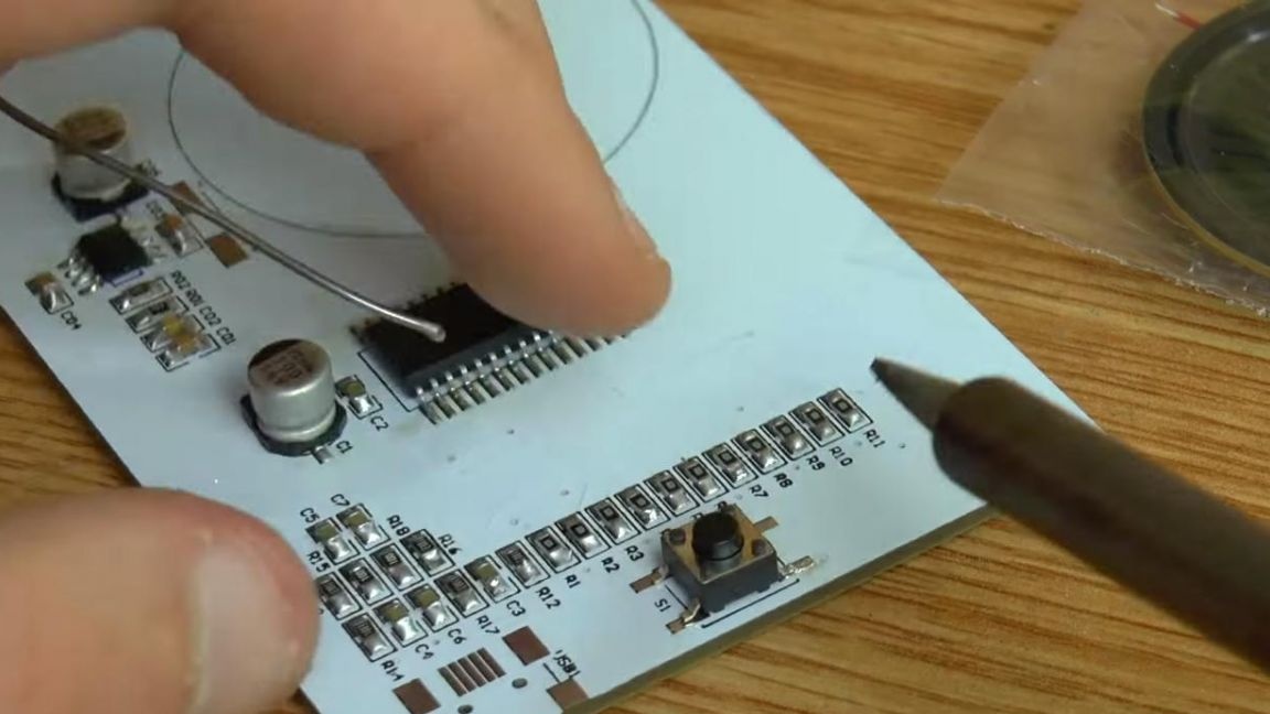
It's time to put the chips in place. We install the microcircuit, being guided by the key on the board marking in the form of a semicircular recess, on the microcircuit case the key is made by a point from the side of the first contact. First, solder one of the extreme conclusions, then solder the rest, do not forget to use flux.
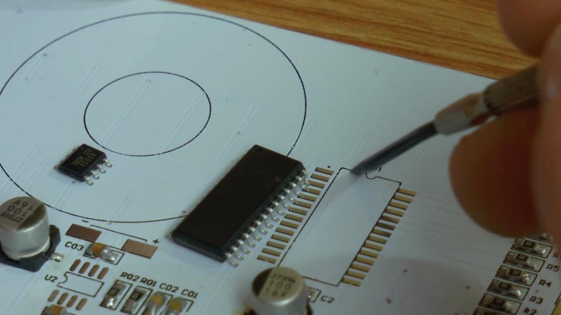
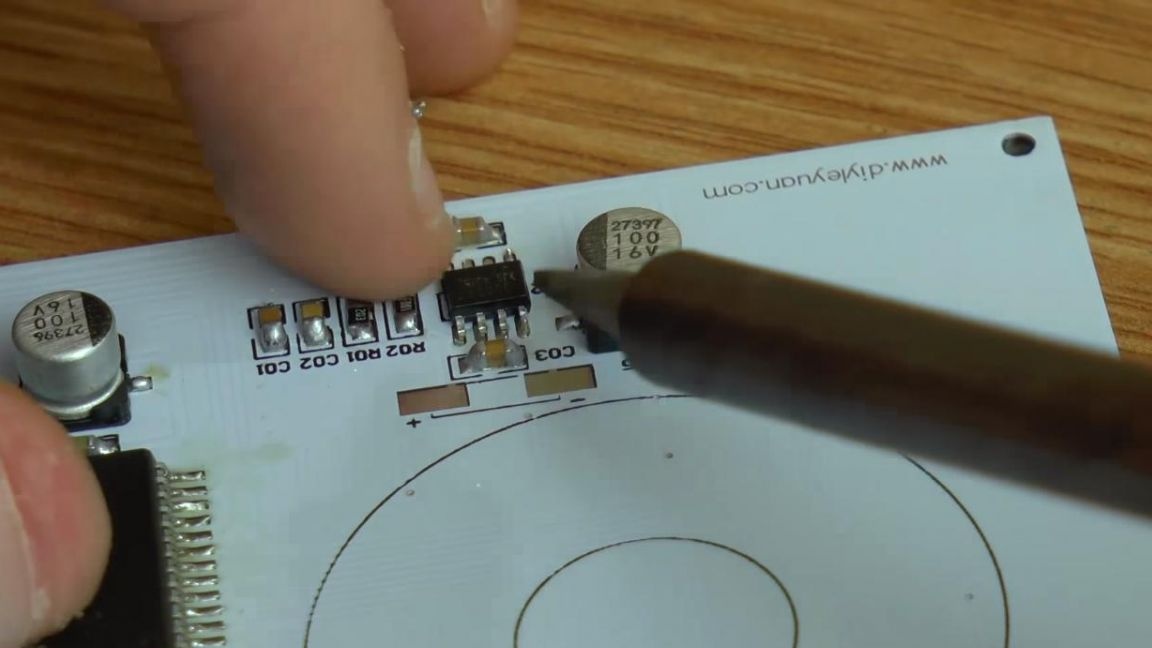
Similarly, install a smaller chip.
Step Five
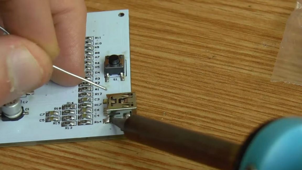
The assembly is almost ready. Solder the button with four contacts, then the microusb port for connecting power and wire to the speaker.
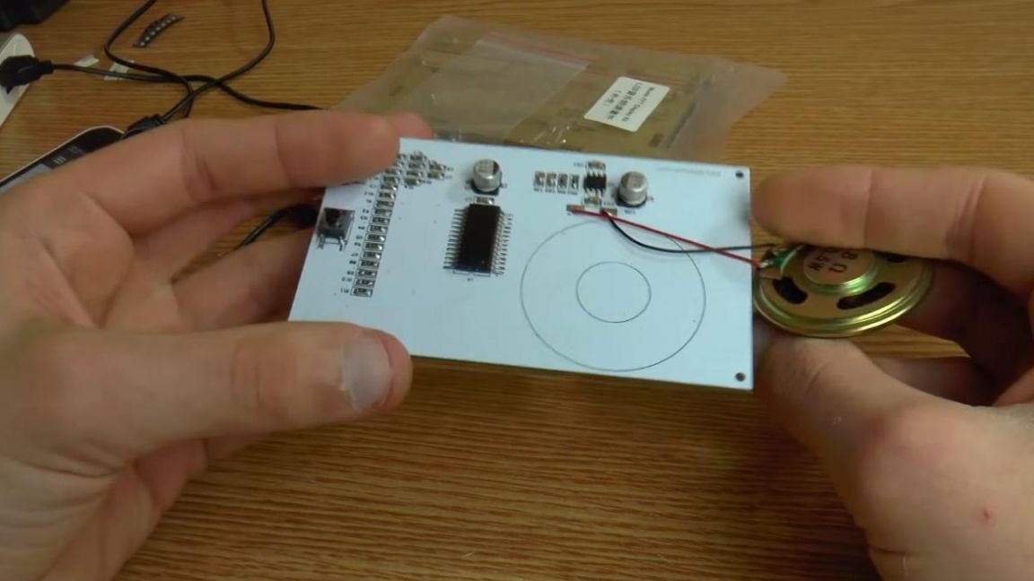
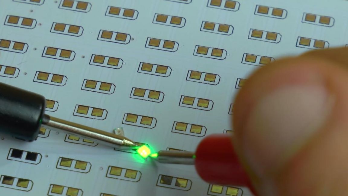
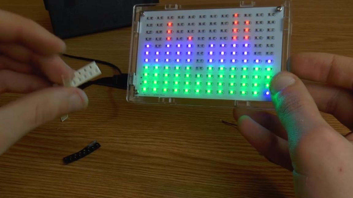
Before installing in the case, we check the set in operation.
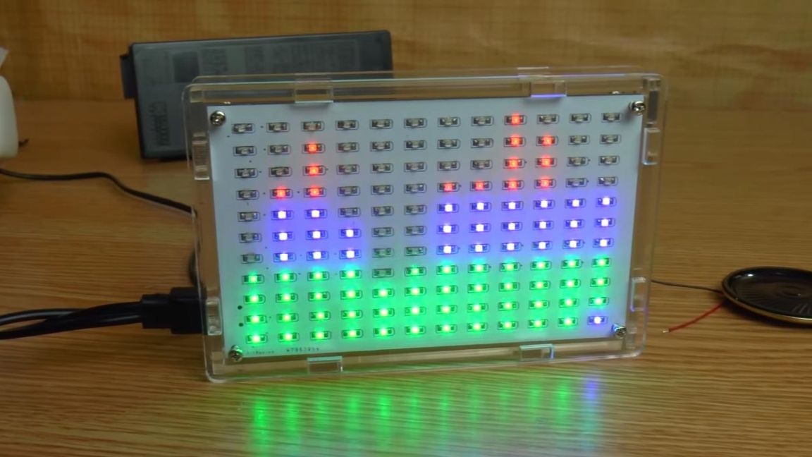
We connect the power bank and connect the 3.5 mm plug to the phone, the LEDs glow in time with the music, which means everything works and you can assemble the case.
Step Six
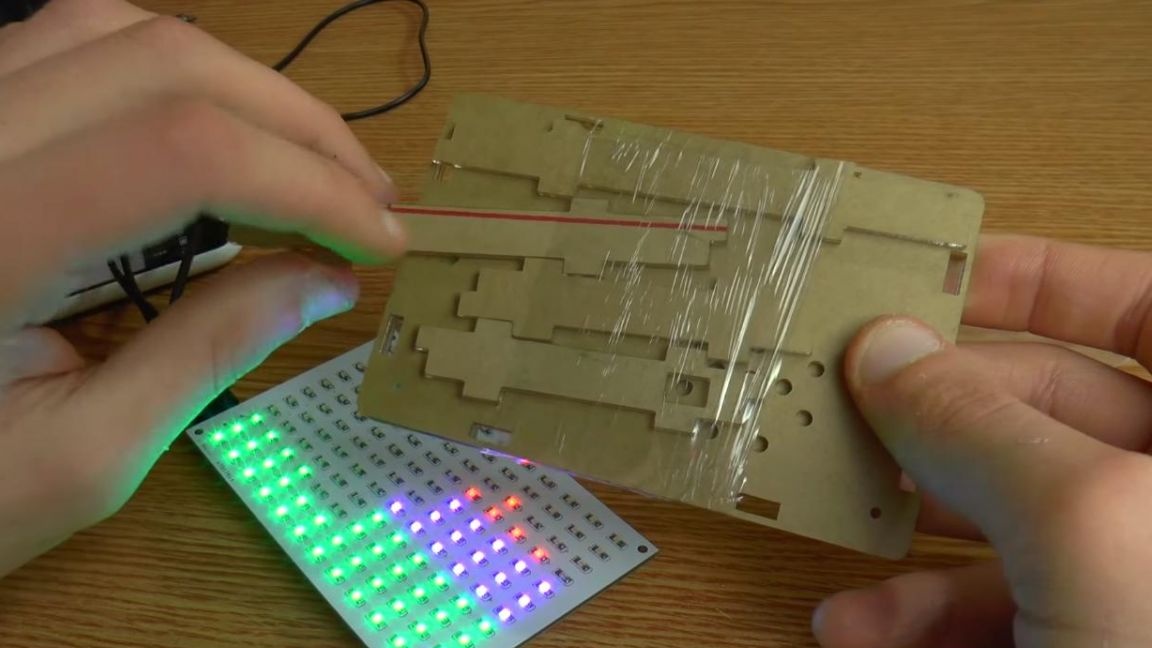
Now let's assemble the case. We assemble the case from plexiglass, before that we remove the protective film from all sides and twist the parts at the four corners with screws and nuts.
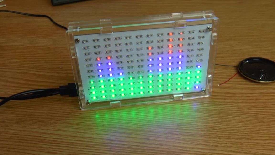
As a result, we got such a nice spectrum analyzer, in the case it looks much better, and its transparency gives a certain originality, also, just in case, we put spare resistors and LEDs in the kit.
The only thing that needs changes is the speaker, I do not recommend using it, since the sound quality is, to put it mildly, not very, there are no low frequencies at all.
That's all for me, thanks for your attention and good luck in assembling kit-sets and home-made products.