
Hello to all lovers homemade. In this article I will tell you how to make a LED strobe do it yourself, it will be based on a kit, which can be ordered from the link at the end of the article. This kit kit will be useful for assembly by beginners, as well as those who want to make a flasher based on it.
Before you start reading the article, I suggest watching a video with a detailed process of assembling a kit kit and testing it in work.
In order to make an LED strobe with your own hands, you will need:
* Kit
* Soldering iron, solder, flux
* Side cutters
* Multimeter
* 12 volt power supply or battery
* Device for soldering "third hand"
Step one.
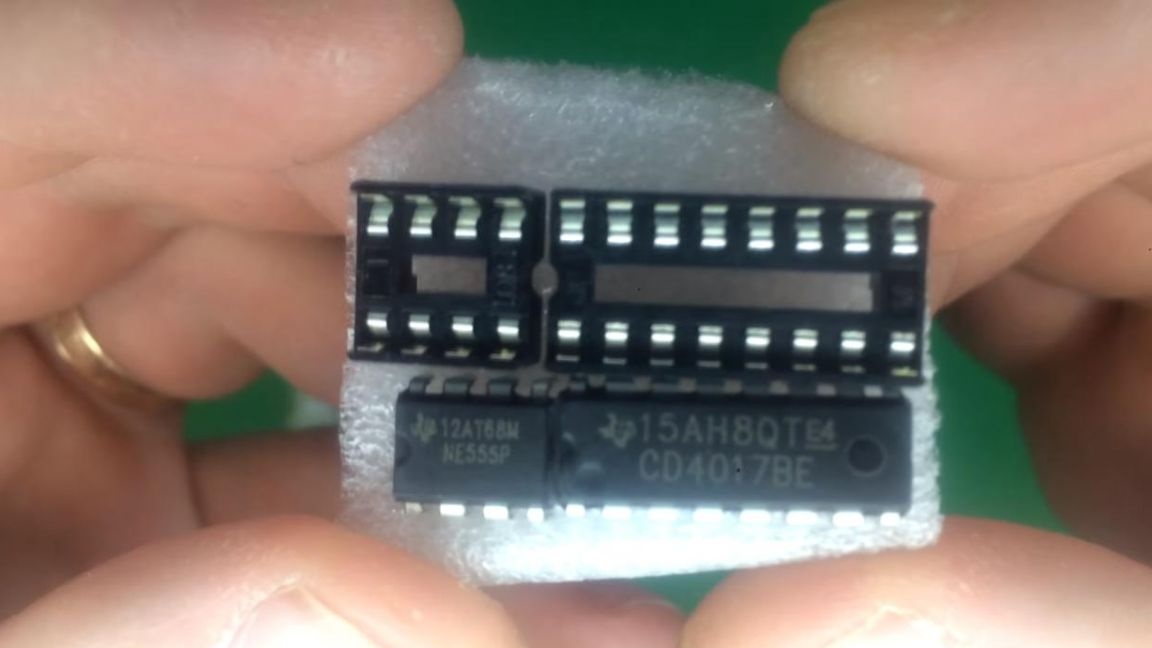
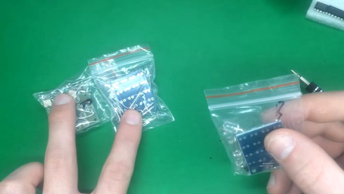
The radio designer kit comes with two sockets for installing microcircuits, four printed circuit boards with all the necessary notation, as well as other radio components, such as resistors, diodes, LEDs and capacitors.
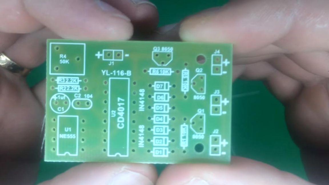
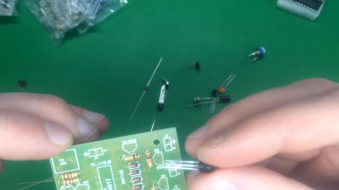
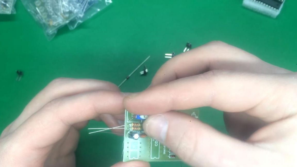
First of all, we install the resistors in their places, their values are indicated on the board.
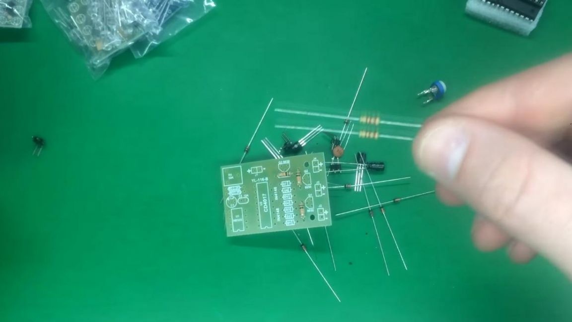
You can determine the resistance of resistors using a multimeter, as well as color coding with a table or online calculator. The first method is the most convenient and fast, but if you do not have a multimeter, then it is also possible to find out the ratings in the following two ways, spending a little more time. On the reverse side, we bend the conclusions of the radio components so that they do not fall out when soldering. Next, we install diodes on the board, there is a strip on their case, just like on the board, we focus on it.
Step Two
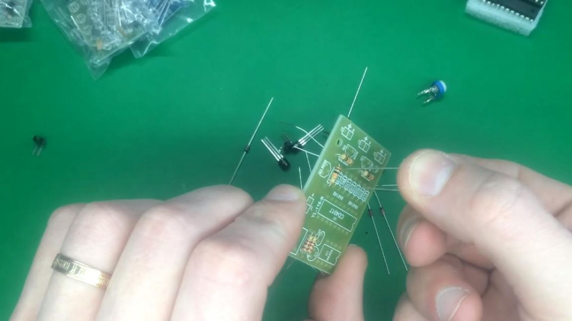
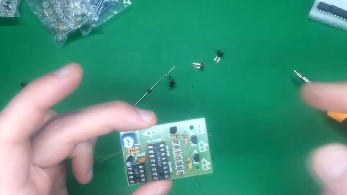
Then we insert transistors, we are guided by the designation on the board, which repeats the shape of the case.
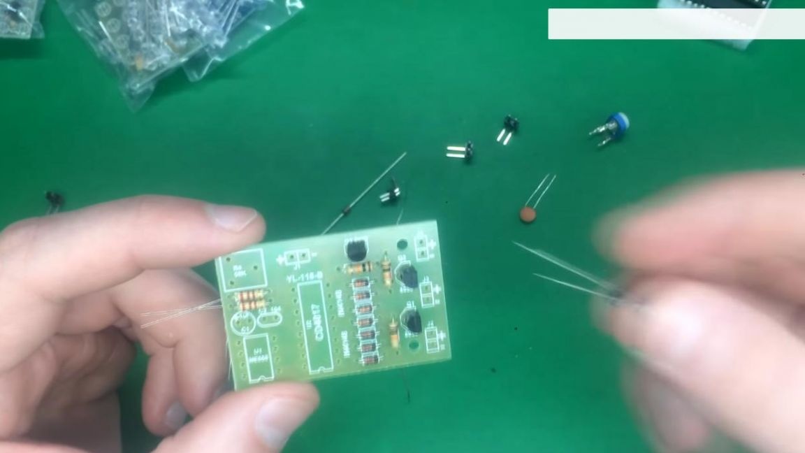
Next, we install the capacitors, on the board the electrolytic capacitors are indicated by a circle, plus is marked on it, the minus of the capacitor is indicated on its case by a white strip, also the long leg is a plus.
Then we insert a non-polar ceramic capacitor with the marking 104 and after it a tuning resistor, which will allow you to change the frequency of the strobe.
Step Three
To connect the microcircuits, we install the sockets.
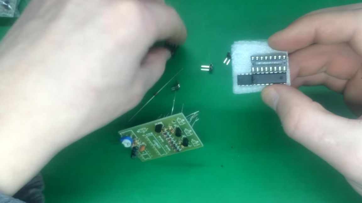
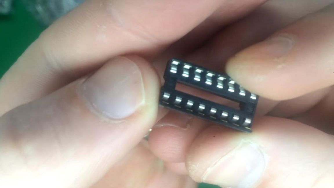
We insert the slots into the holes on the board, being guided by the key in the form of a recess on the case and on the board designation. Contacts for connecting power and LEDs will be installed later.
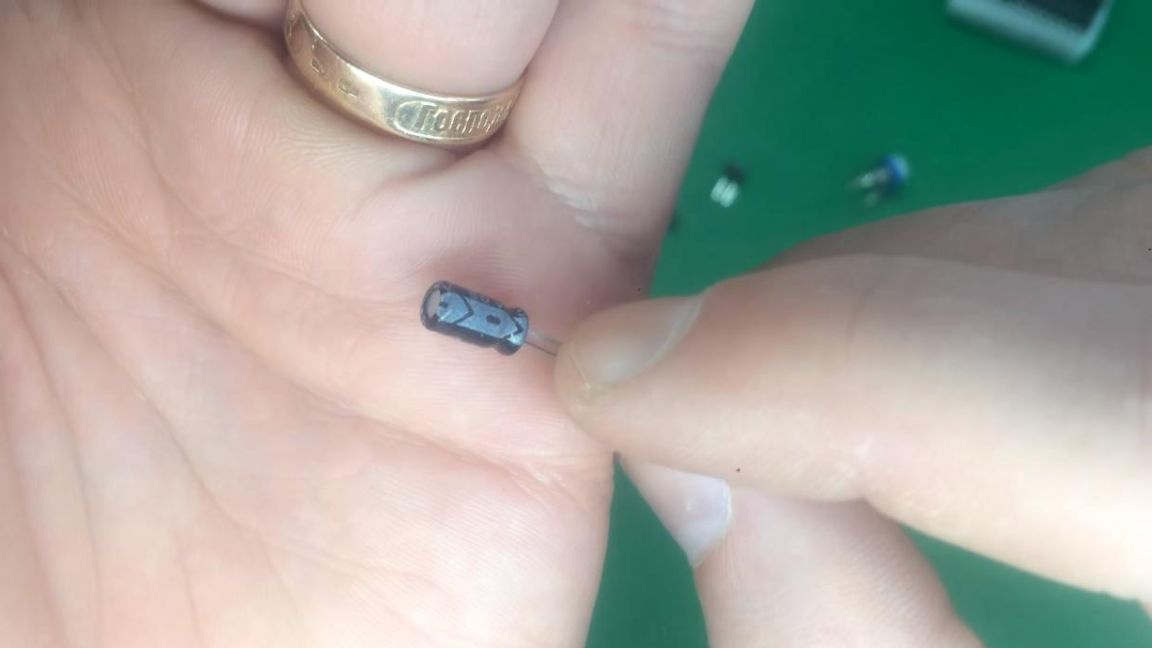
Of the spare parts there was only one diode, apparently for reinsurance.
Step Four
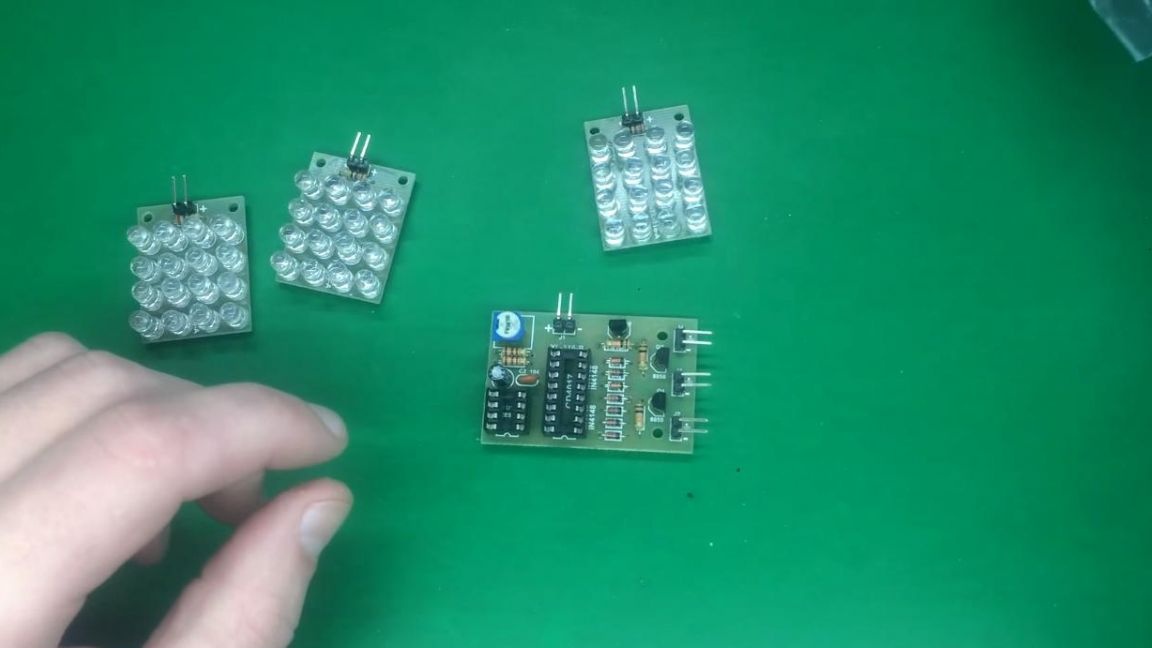
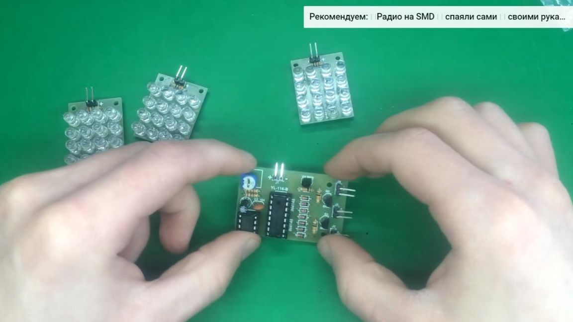
Now we will assemble a board with LEDs, three of them are included, each color has its own LED color.
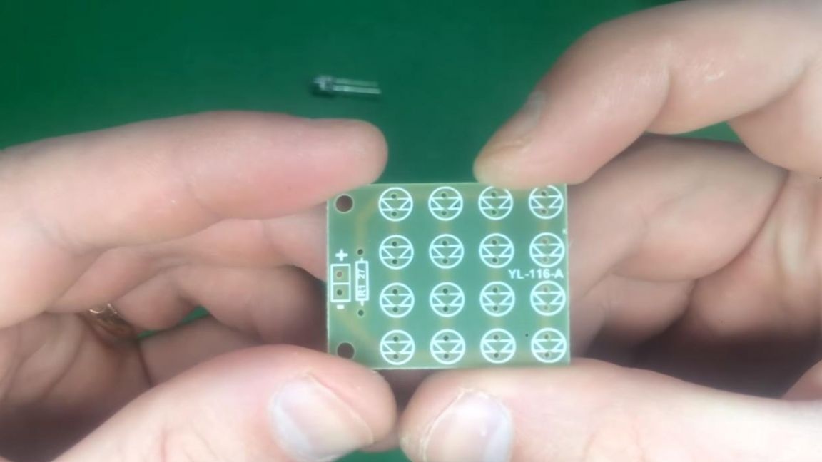
We first install the resistor, and then the LEDs, while observing the polarity, the long leg is plus, short-minus, on the board the minus is indicated by a dash, plus-triangle.
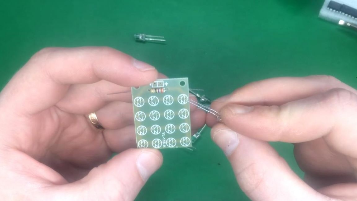
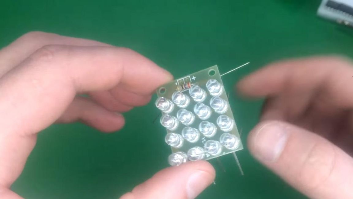
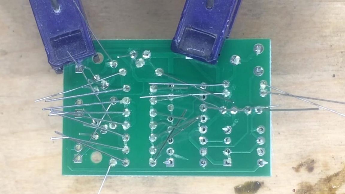
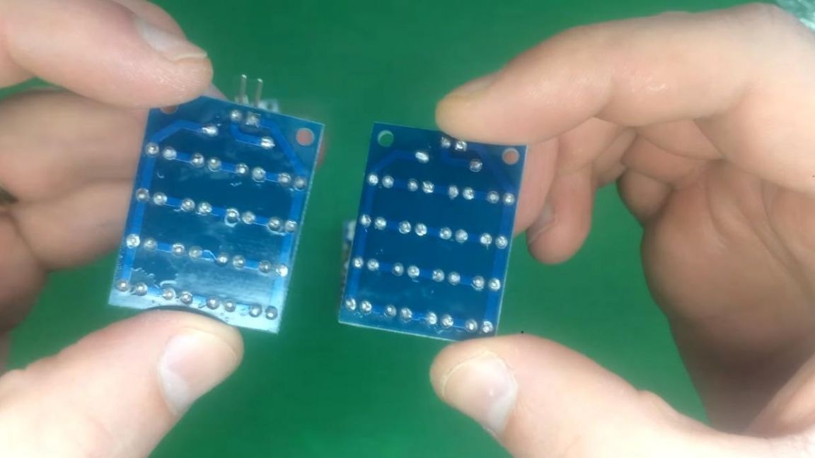
The rest of the boards do the same. On the reverse side of the board, we bend the terminals of the radio components, after which we fix the board in the third-hand soldering device and apply the flux to the contacts.
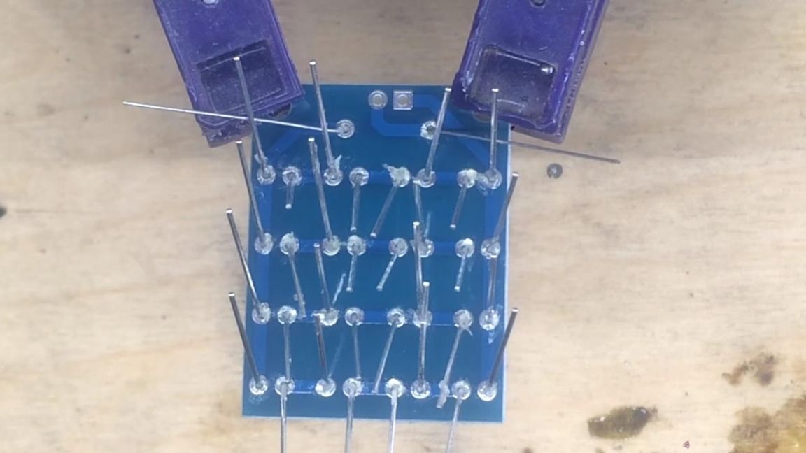
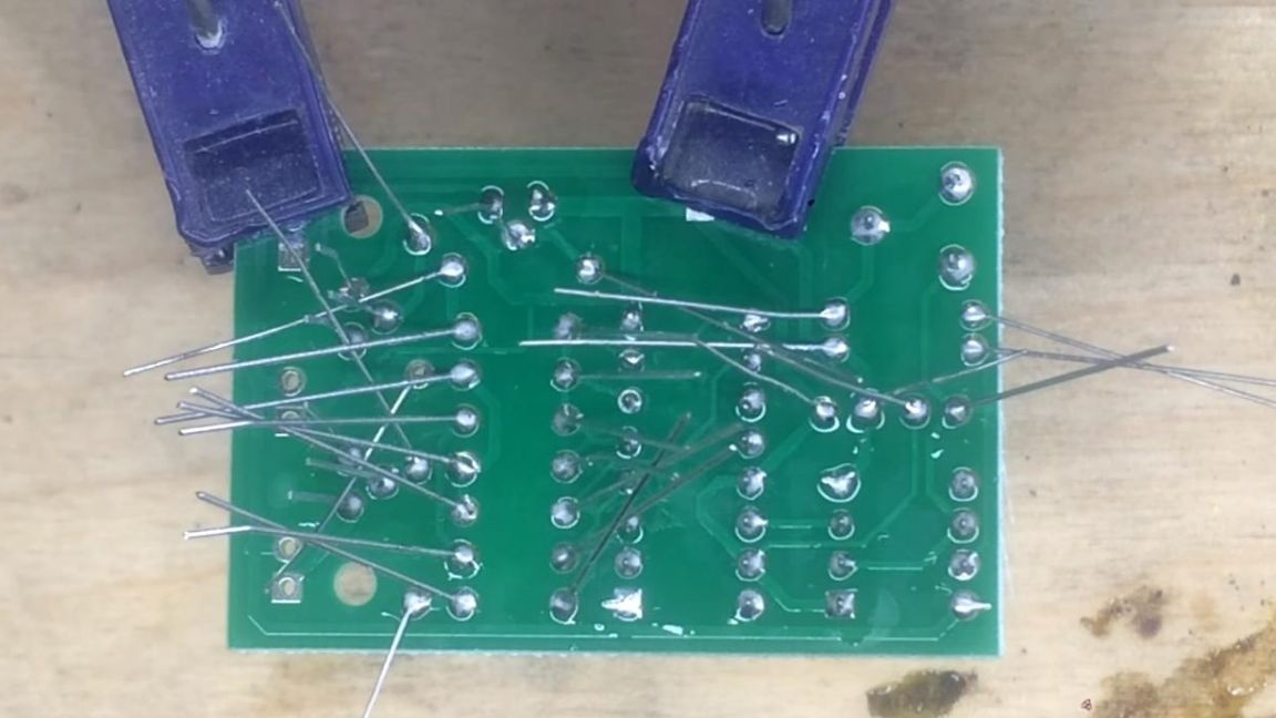
Next, using a soldering iron, solder the contacts, slightly adding solder.
Then we take the main board with microcircuits and do the same, also solder the conclusions for connection to the boards.
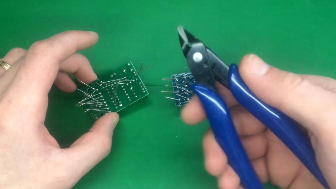
Step Five
After soldering, we remove the remnants of the conclusions using side cutters. When biting off the excess parts of the legs, be careful, you can accidentally tear the track off the board.
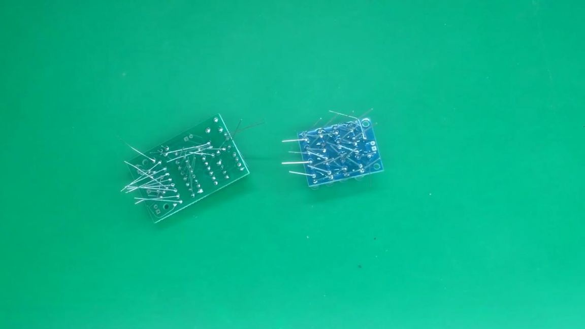
Next, we clean the circuit board from the remaining flux; for this, a brush and galosh gasoline or other solvent, such as acetone, are well suited.
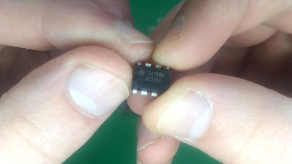
Then we install the microcircuits in the sockets according to the key on their case and board.
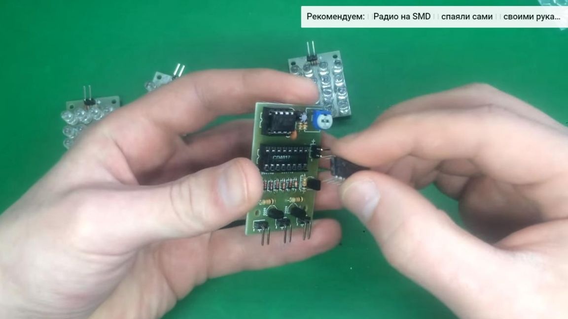
After that, we connect the boards to each other using the wires that came in the kit.
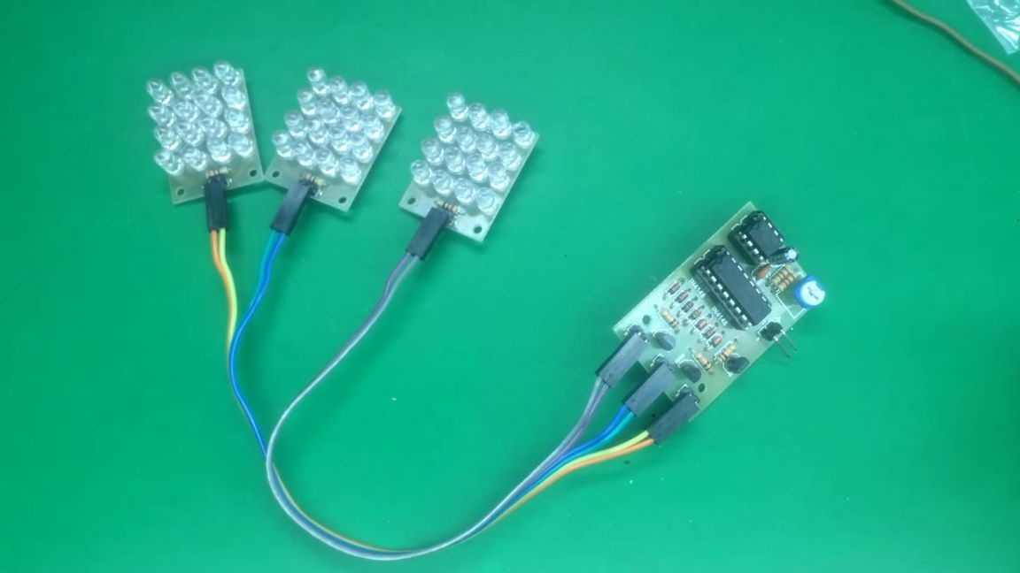
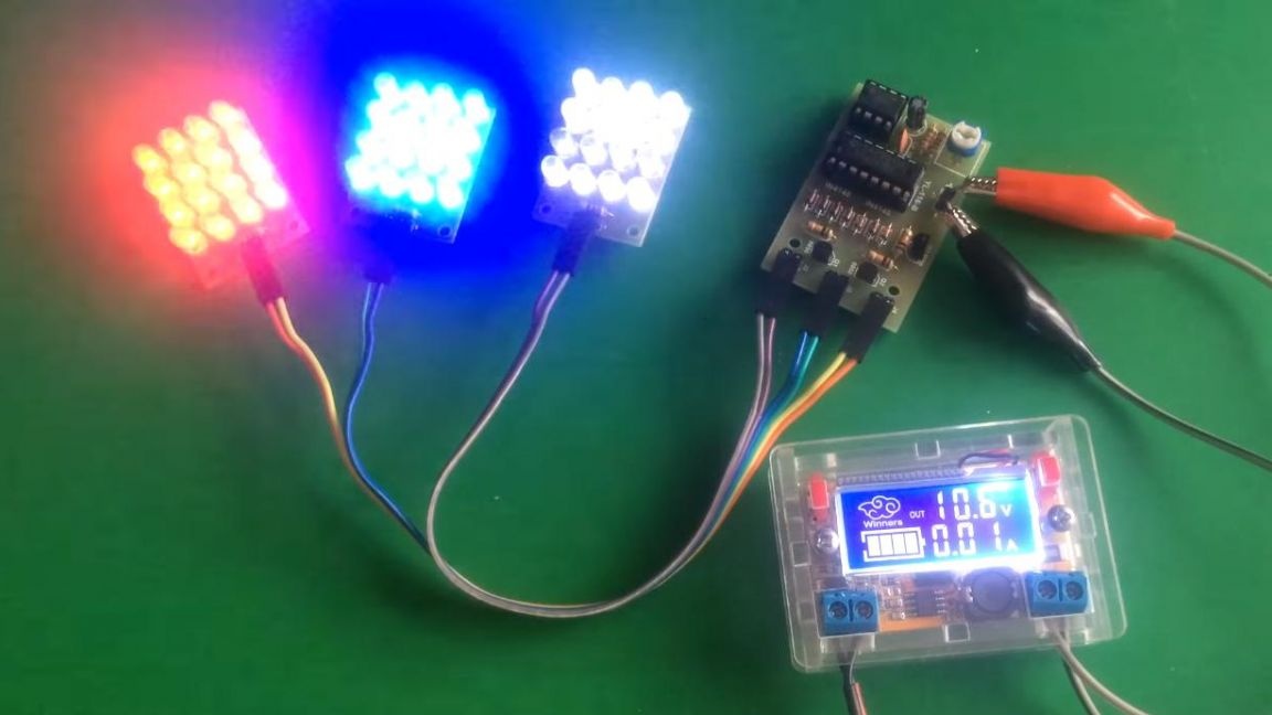
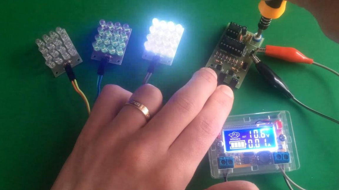
The strobe is ready, you can check in operation. We connect the power supply to the contacts of the main board, observing the polarity.
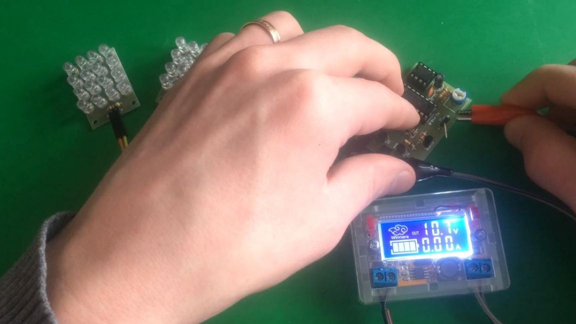
The LEDs alternately light up, the strobe frequency can be changed by simply rotating the variable resistor with a flat-head screwdriver.
That's all for me, this LED strobe can be used for any purpose, possibly with light music with some modifications, as well as in order to gain experience in working with radio electronics.
Thank you all for your attention and creative success.