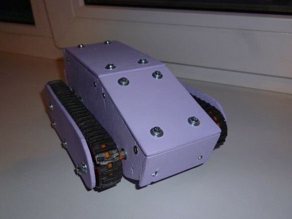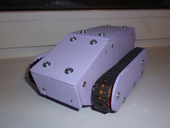
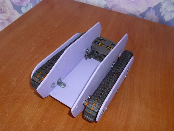
Good afternoon, today I want to share instructions for making a toy tank controlled by an Android phone’s accelerometer. The base of the tank will be made of colored plywood 3 mm thick. Caterpillars and dual gear motor of the well-known company Tamiya. Producing quality and inexpensive parts.
For the tank we need:
- Tamiya 70168 dual gear
- Tamiya 70100 set of rollers and tracks
- Tamiya 70157
- Plywood 10 mm (a small piece)
- Arduino Pro Mini 5V AtMega 328
- DRV 8833
- Bluetooth module HC-06 or equivalent
- USB-UART for Arduino firmware
- Rectangular red and green LEDs
- White LEDs 5 mm 2pcs.
- Resistors 3x 150 Ohms
- Li-ion 18650 batteries
- Dupont Dad-Mom Connectors
- Wires of different colors
- solder
- Rosin
- soldering iron
- Bolts 3x40, 3x20, nuts and washers for them
- 2x10 wood screws
- Wood drills 3 mm and 6 mm
- Electric fret saw
- Acrylic paint
Step 1 Assembling the gearmotor.
I like to use Tamiya gear motors. They stand acceptable, assemble easily. Tamiya 70168 has four build options. Depending on the desired gear ratio and position of the output shafts.
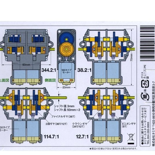
Detailed instructions are enclosed inside the gearbox. We need the output shafts to be closer to the engines, and the gear ratio 114.7: 1. We select the option we need and collect everything according to the instructions, except for installing motors. It is more convenient to put motors later, in addition, wires and capacitors must be soldered to them before installation.
Step 2 Production of body parts.
The case will be made of plywood 3 mm thick. Download the following image and print it on A4 sheet at a scale of 102%.
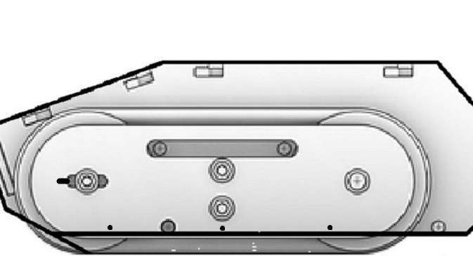
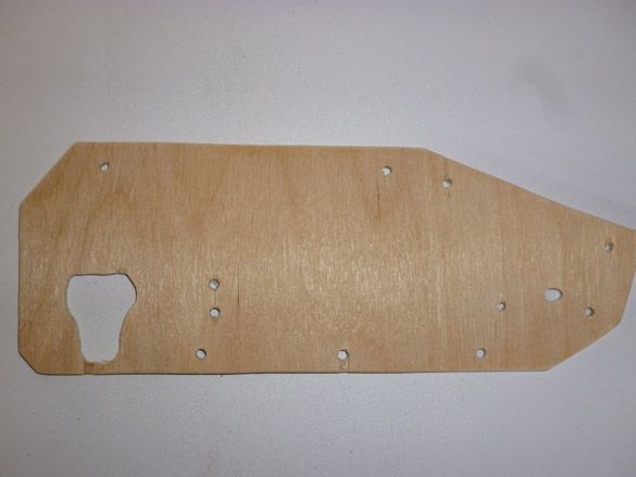
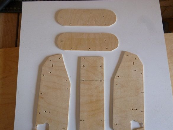
Now we take two pieces of plywood of sufficient size, put one on the other, apply our picture on top. 3 mm holes should be made in the areas marked with a bold dot. So that both parts are the same, first we drill a sheet and two plywood at one of the points, insert a bolt there, and twist the picture and two pieces of plywood together. Then the second hole, and also insert a bolt there. After that, we drill all the rest. Pay attention to the leftmost hole, it is necessary to give it an oval shape. This is necessary to control the tension of the tracks. Now we take a jigsaw, and immediately cut out two side parts of the case, following the bold line of the picture. Two such details should turn out:
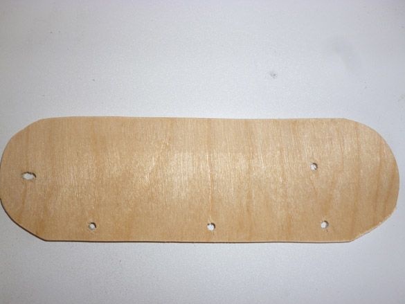
Next, you need to do all of the above, only this time we cut out two details covering the tracks. It is necessary to cut on the small oval drawn in the picture. As a result, we get two more details:
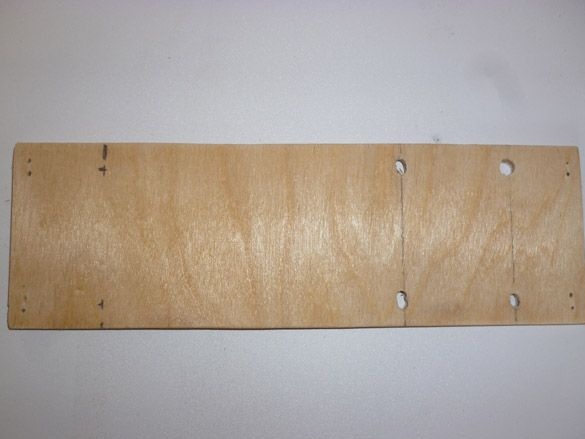
Now we take a sheet of plywood in one layer and cut a rectangle with dimensions of 168 x 54 mm. This will be the bottom of our tank and the part to which the gear motor is attached:
To start the assembly, we need all the details described above:
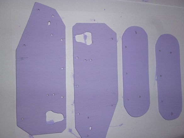
You can leave all the details as they are, but I prefer to paint them. Acrylic paint is suitable for painting. It dries quickly and does not smell, which means you can paint in any room without fear of poisoning. So, we paint the cut out details:
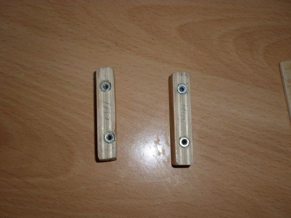
Now we need 10 mm plywood or a suitable wooden stick. It is necessary to cut a rectangle measuring 54 x 15 mm and a thickness of 10 mm. This part is necessary to connect the housing together. Having made a rectangle, we drill two holes at a distance of 15 mm from the edge, first with a 3 mm drill and then 6 mm, but not through and through, but only half the depth. Insert the nuts into the holes obtained and fix them with glue. We need four such details:
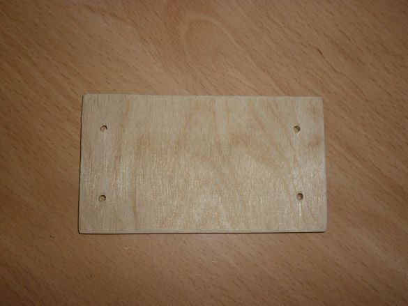
Again we take plywood 3 mm thick. Cut a rectangle 107 x 60 mm. Retreating 15 mm from the edges of the drill hole 3 mm, this will be the top cover:
We cut the next rectangle measuring 33 x 60 mm. Backing 15 mm from the edges, we drill two holes with a diameter of 5 mm. Cutting and stripping a part we paint it. Then we insert white 5-millimeter LEDs into the holes made. We solder them in parallel and fix using hot melt adhesive:
Step 3 Assembly of the housing.
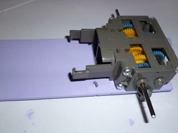
Having prepared the gear motor and parts, we proceed to the assembly of everything together. To get started, take the lower part of the case and fasten the gear motor to it:
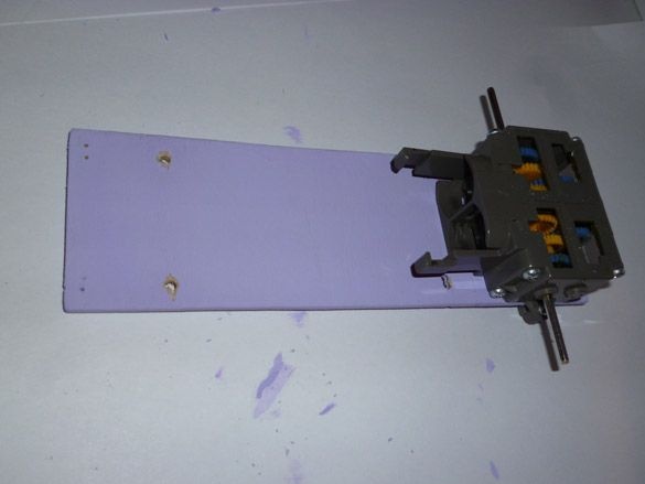
And a little bigger:
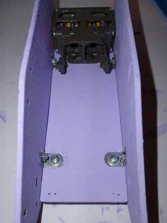
Then we fix the side parts, using corners from a children's iron constructor and 3x20 mm bolts for this:
Now we need to install the tracks. We take the details of the closing tracks. We insert 3x40 mm bolts into the holes. We put a big wheel on the front bolt, on the bottom three small ones, then the washers and tighten the nuts, but not tight, so that all the rollers spin freely. We put large sprockets on the shafts of the gearmotor. We combine all the bolts with rollers with holes on the side parts. After passing the bolts, we wind and tighten the nuts from the inside of the case. We put on the tracks, check if they are tight enough. Caterpillars should not sag, but too much tension will damage them. Adjustment is carried out by the front wheel, moving it or vice versa, moving it away from the gear motor. After all the manipulations we get:
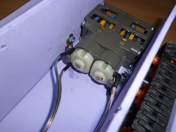
We take the motors that come with the rollers and tracks. We solder to the contact pads of the wire, and in parallel with them a 0.1 microfarad capacitor. After that, install the motors in the gear motor:
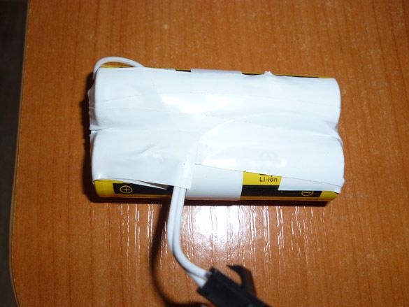
Let's move on to the batteries. We solder our Li-ion 18650 batteries in parallel and output the wires for convenience. Twist them with electrical tape:
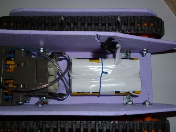
We place them at the bottom of the case, next to the motors:
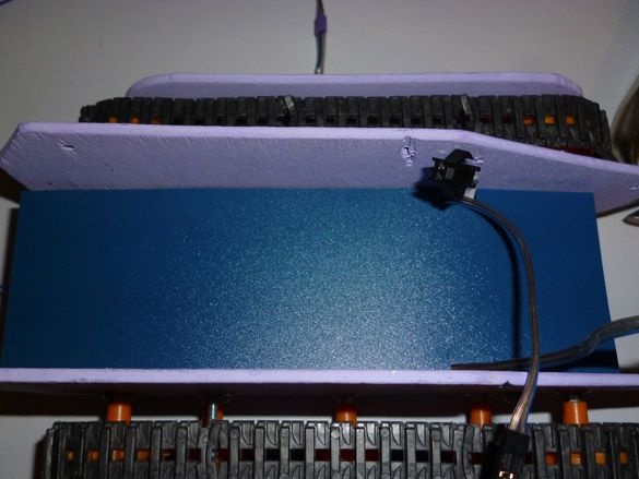
For convenience, as well as the separation of mechanical and e parts, cut out a rectangle of 100 by 54 mm from thin plastic or cardboard. Place it on top of the gearmotor and batteries:
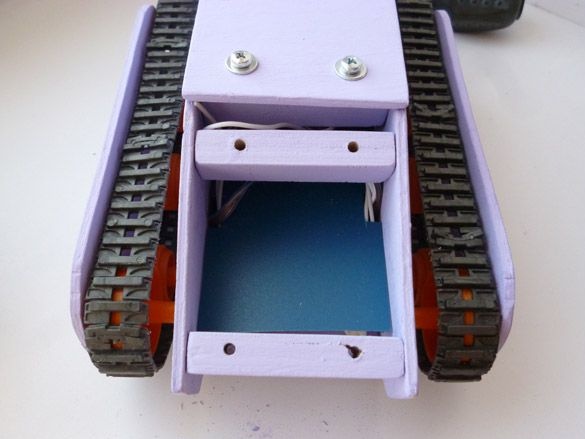
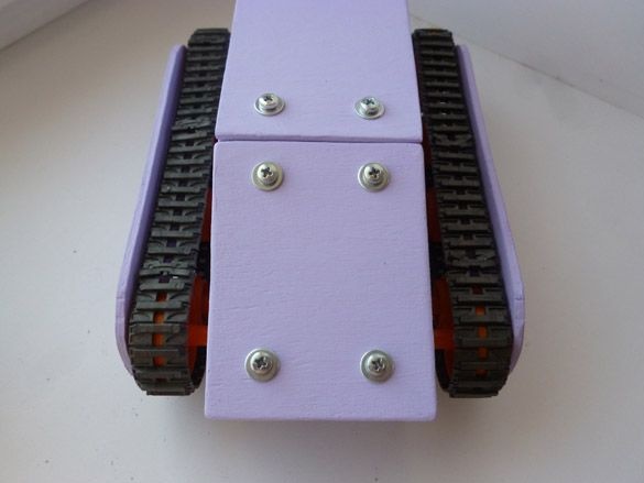
We take fasteners and install them as shown in the photo. We fasten to the side parts using screws:
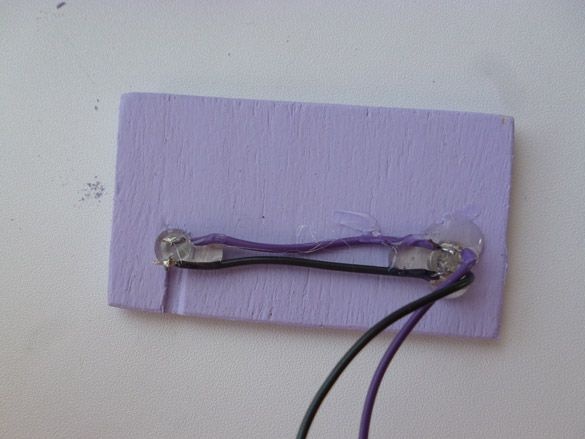
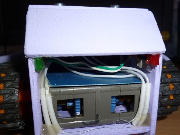
In the back of the tank, we attach rectangular LEDs to hot glue. Red and green:
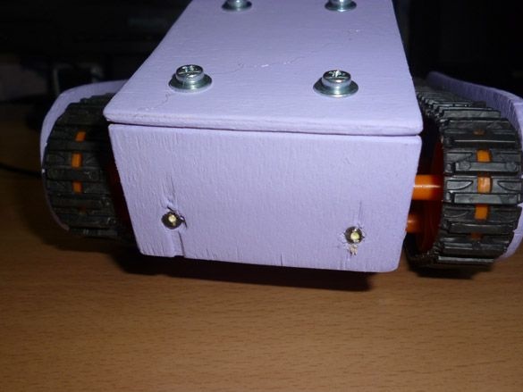
I also use hot glue to fix the front part with the headlights:
Step 4 Electrics
Electric motors interfere with their operation, and a voltage drop occurs during start-up. So that at each start of the engines the Arduino does not overload, we will divide the power supply. Arduino is powered by a 9-volt battery of the crown type, and motors from batteries. We have already placed the batteries, we will place the crown in front of the tank:
After installing the battery, close it with the upper cover:
We connect everything together according to the scheme:
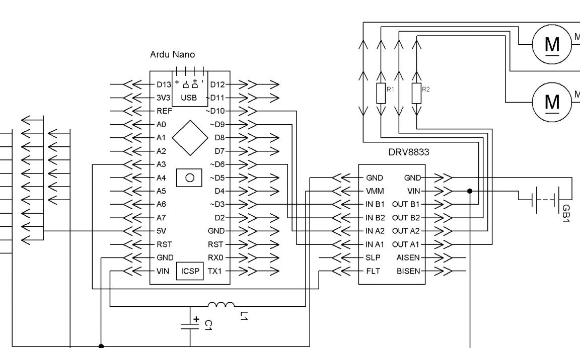
I will explain a little. The left motor through the driver is connected to the 5 and 6 pin. Right - to 9 and 10. Plus from the red LED through the resistor to 3 pin, minus to GND. Plus from the green LED, also through the resistor, to 4 pin. Headlights to 2 pin.
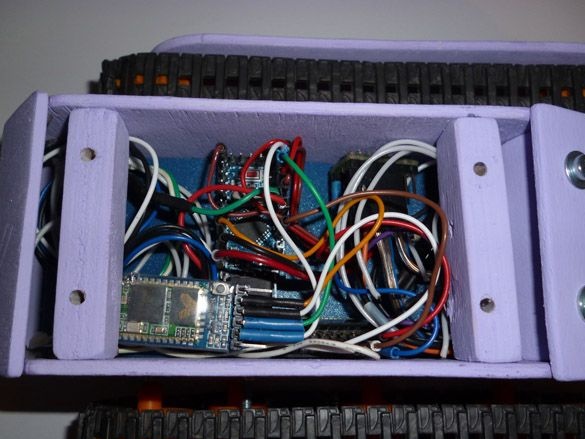
The operation of the Bluetooth module is carried out through the SoftwareSerial library.We will use the software com-port. Connection contacts can be changed in the sketch. We connect the module as follows:
Arduino Pro Mini - Bluetooth
D7 - RX
D8 - TX
5V - VCC
GND –GND
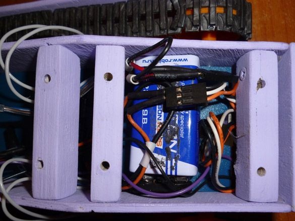
Putting it all together we place an electrician in the central part:
Step 5 Software.
To work with the sketch, you need to download the Arduino IDE. We go on and download the latest version:
Then you need to add the library. SoftwareSerial should already be in the Arduino IDE. But just in case, I'll post it:
If the Arduino IDE, when compiling the sketch, gives an error and swears at the missing library, unpack the downloaded archive into the “libraries” folder located in the folder with the Arduino IDE installed.
Step 6 Prepare the Bluetooth module.
The default settings of the Bluetooth module are different from what we need. Therefore, you must first establish the connection of the Bluetooth module with the computer and change the settings. Fill the Send_ AT_Bluetooth sketch into the Arduino:
Arduino will act as a link between Bluetooth and the computer. Launch the Arduino IDE, open the Port Monitor. For HC-06, select 9600 in the port monitor settings, NL and CR are not needed. If a Bluetooth connection is not established with the module, it is in AT command input mode. Perhaps the first time the module will not respond. Then try overloading it by disconnecting and reconnecting the plus wire. All commands are entered without quotes, do not forget to press enter to send. We enter the following commands:
"AT" - without quotes, the answer "OK" should come.
“AT + NAME
“AT + BAUD7” - set the speed to 57600.
“AT + RESET” - we overload the module.
If something went wrong, or don’t remember the settings:
“AT + ORGL” - return the module to the factory settings.
Step 7 Fill the sketch.
After setting up the Bluetooth module, proceed to fill in the main sketch:
Step 8 Prepare your Android phone.
Before use, make sure that your Android phone or tablet has an accelerometer. To get started, add a bluetooth device tanchka in Android. We go into the Bluetooth settings, find the Bluetooth module you named and connect. The password for the connection is “1234” or “0000”, it can be different for different models. Now install the control program. We will need an Arduino Bluetooth RC Car or BT Controller. Both programs are free, they have the ability to control the Bkuetooth device through the accelerometer, and they are in Google play. Download the program you like on your phone or tablet. In the program settings menu, enter the following commands:
W - forward
S - back
A - left
D - right
F or G– stop
K - headlights
L - headlight off
You can also use the joystick to control the tank. It can be made according to my other instructions.
And add a Bluetooth module to it, following another instructions.