
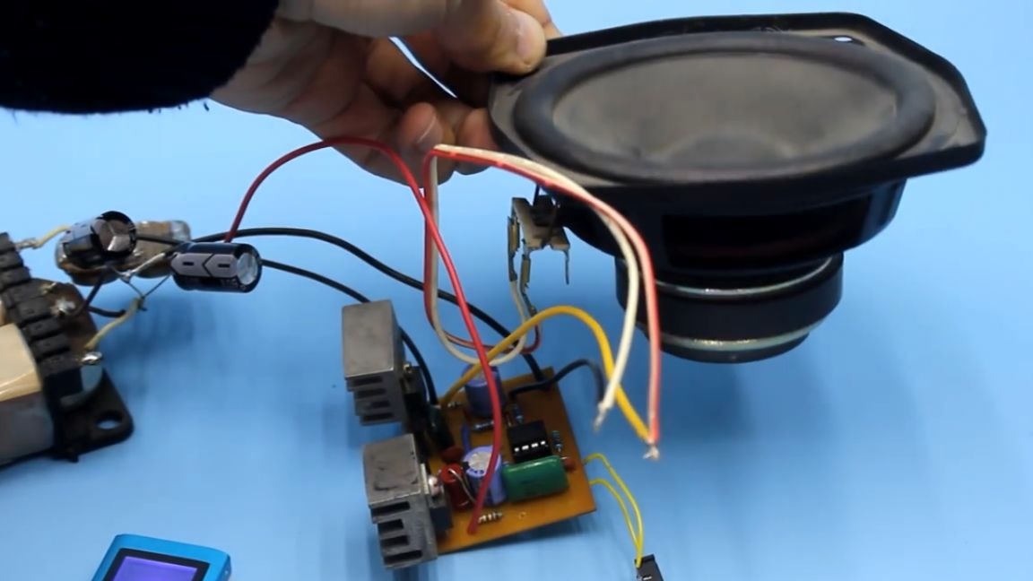
Low frequency power amplifiers, or simply a sound amplifier, are assembled by radio amateurs quite often. Specialized circuits for low-frequency power amplifiers are now quite popular, and after assembling some ULFs based on microcircuits, the amateur radio seeks for something more complicated. Transistor amplifiers, despite the huge variety of microcircuits, have not lost their relevance. If you need a good high-quality amplifier, then it is worth assembling it on transistors. Today we will talk about a good transistor amplifier operating in class b. Do not rush to conclusions, class b is also quite good.
True connoisseurs of super high-quality sound will surely say that this is not the best class of ULF, single-ended and tube - this is what a high-quality amplifier should be like. Of course, I partly agree with you, but the prices of tube amplifiers, you yourself see:


And assembling them at home is also not an easy process.
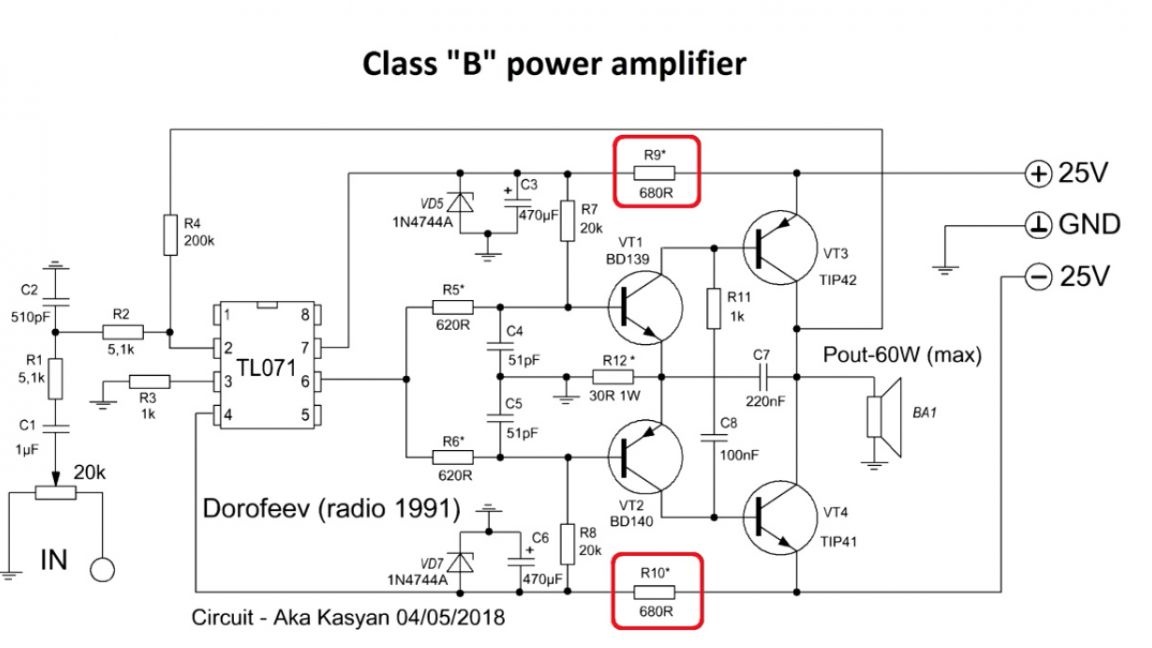
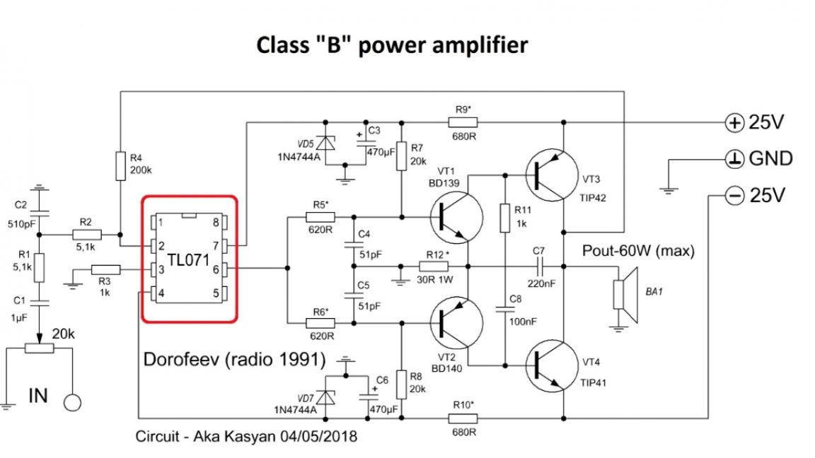
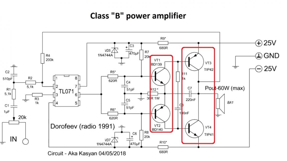
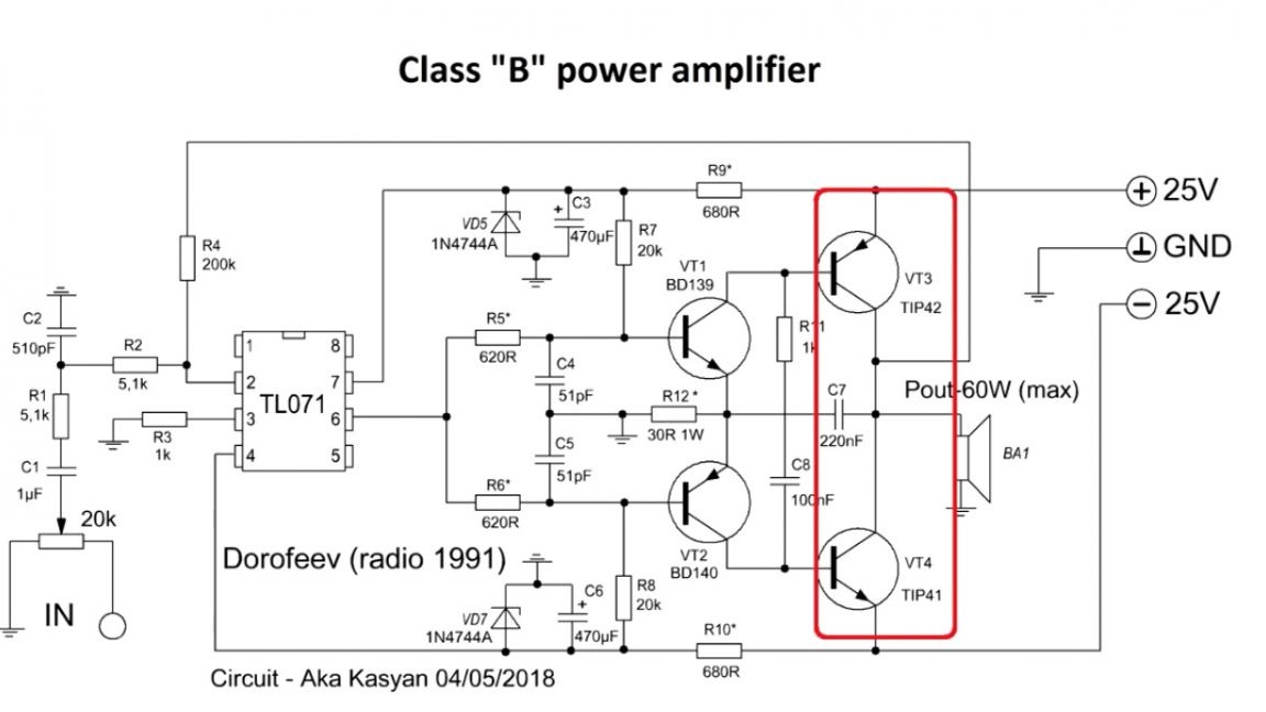
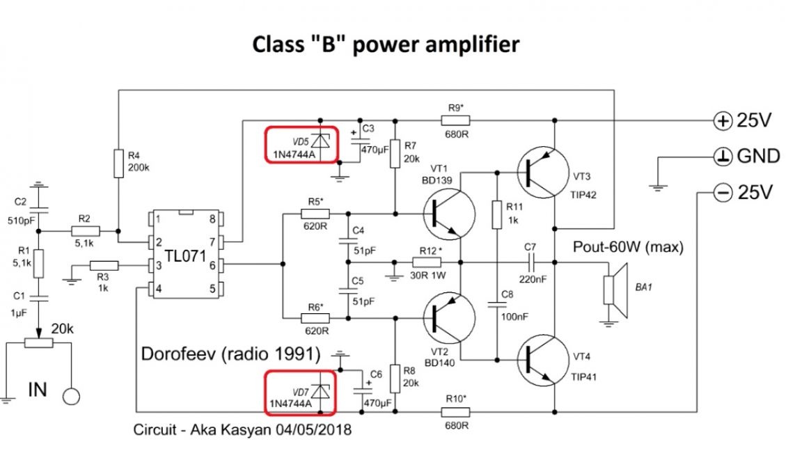
The presented scheme was published in the journal Radio in 1991.
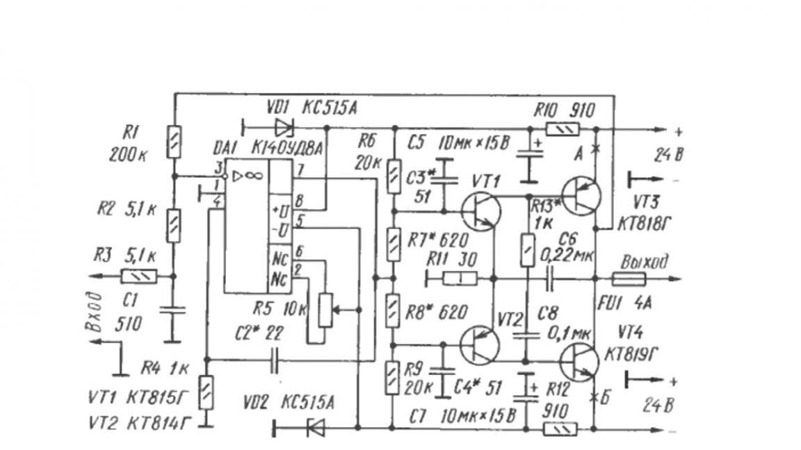
This is the legendary Dorofeev amplifier, so it has a fairly advanced age. The genius of the scheme is simplicity. Despite the minimum number of components used with the appropriate power source, this amplifier is capable of delivering 4 ohms to the load, and power up to 50 watts, which you will agree is very good. At different times, radio amateurs modified and changed the circuit. For convenience, the author transferred the circuit to imported components, then we will consider it.
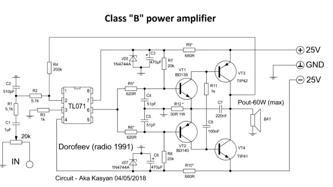
This amplifier uses rather interesting schematic solutions, for example, resistor R12, which limits the collector current of the transistor of the output stage and is a kind of limiter of the output power, while protecting the output transistors from short circuits. So the amplifier is short, one might say, not afraid.
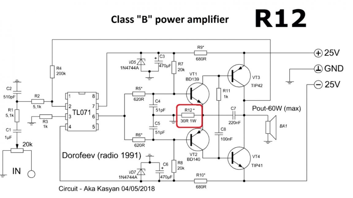
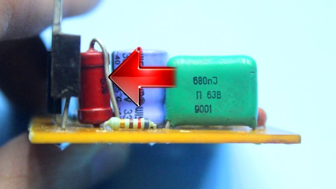
The specified resistor needs a one-watt, in extreme cases, it can be half a watt. The non-linear distortion coefficient at a purity of 1 kHz is not more than 0.1%, at 20 kHz it is 0.2%, so there will be no distortion at the rated power. The amplifier is powered by a bipolar source. The range of supply voltages is from + - 15 to + - 25V.
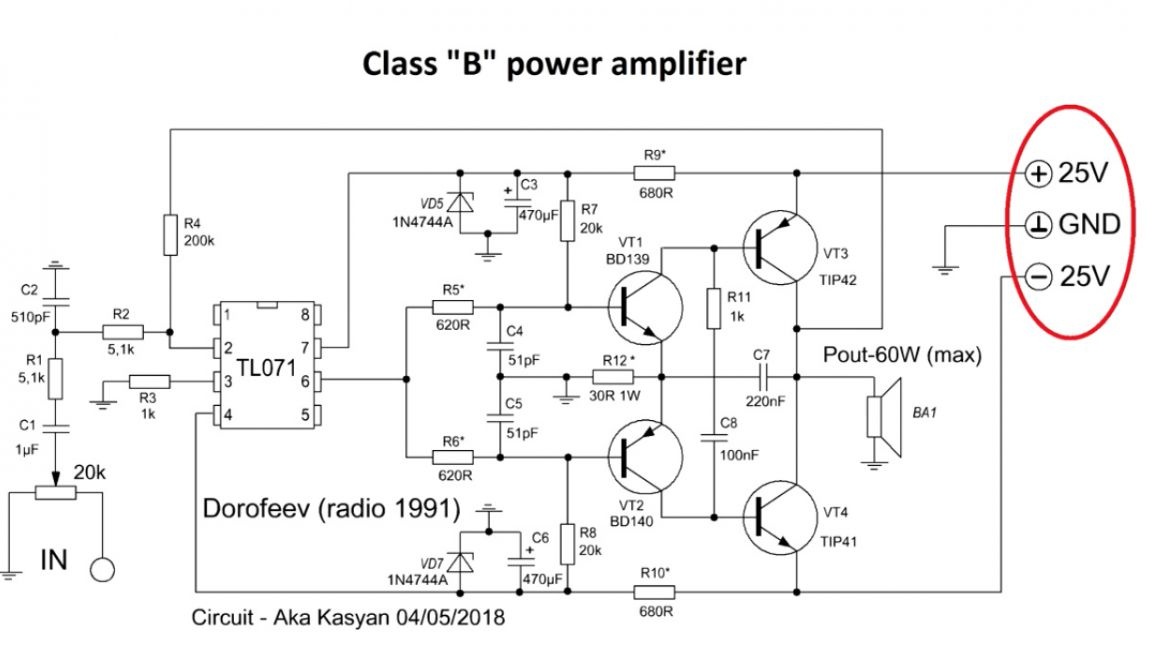
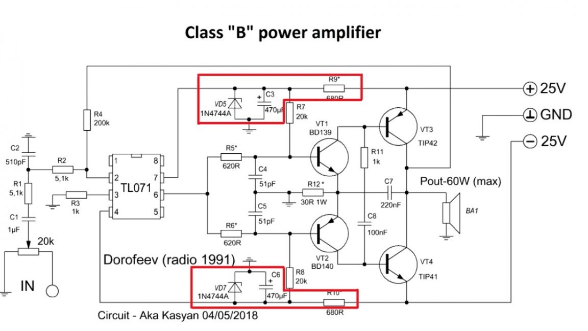
In order to increase the output power, you can increase the supply voltage, but in this case, you need to change the transistors of the final stage to more powerful ones and recount several resistors.
Resistors r9 and r10 are selected depending on the supply voltage.
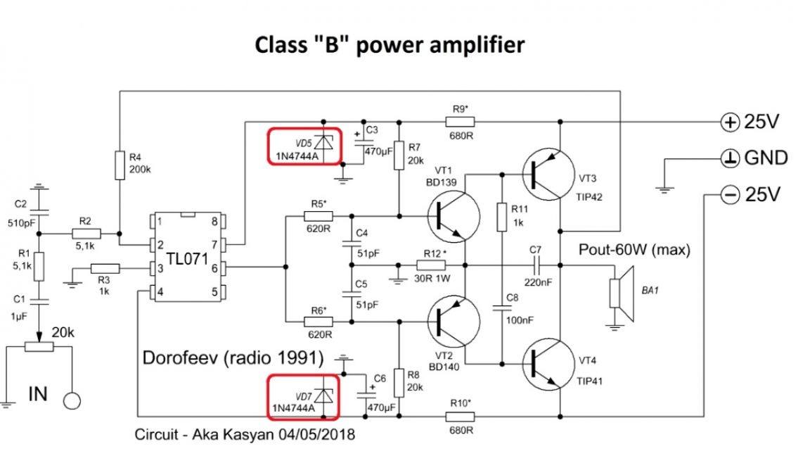
They limit the current through the zener diode and in this part of the circuit a parametric voltage stabilizer is assembled, which provides stable power for the operational amplifier.
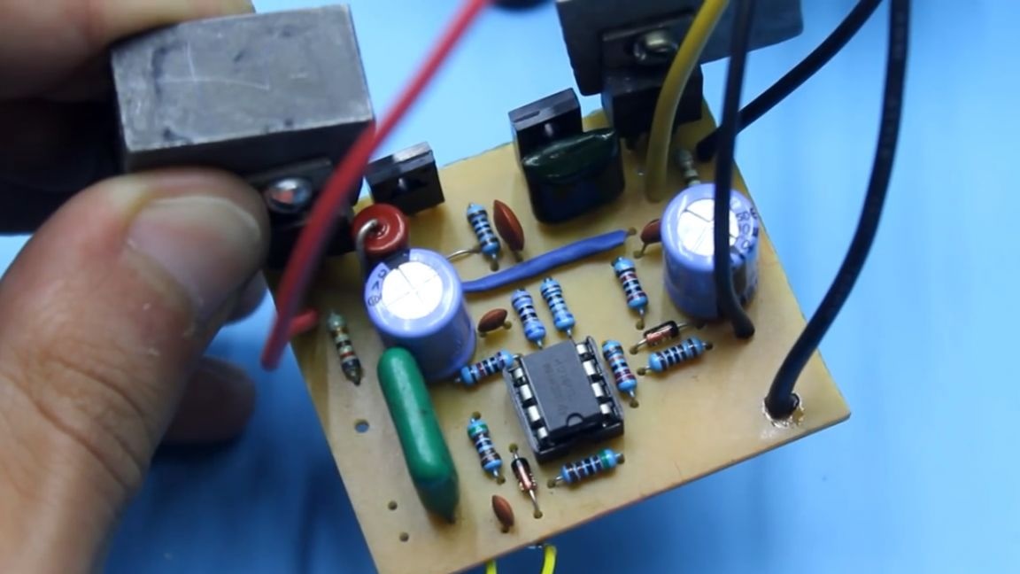
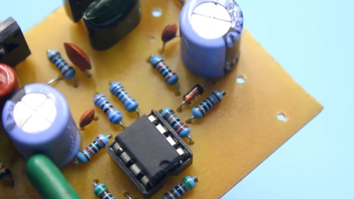
By the way, about the opamp, this is a pretty good operational amplifier, it is used in audio technology very often. You can safely change to TL081.
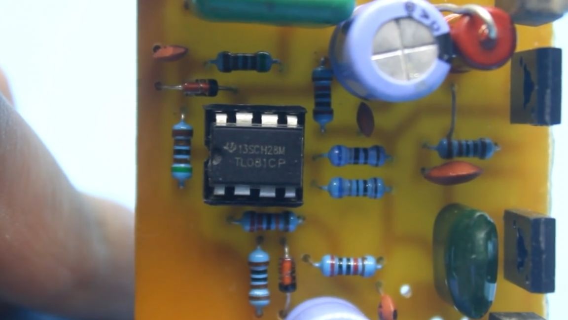
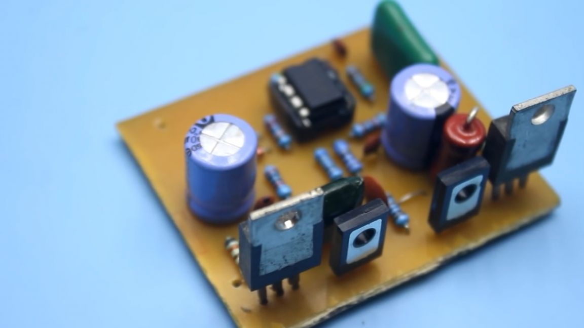
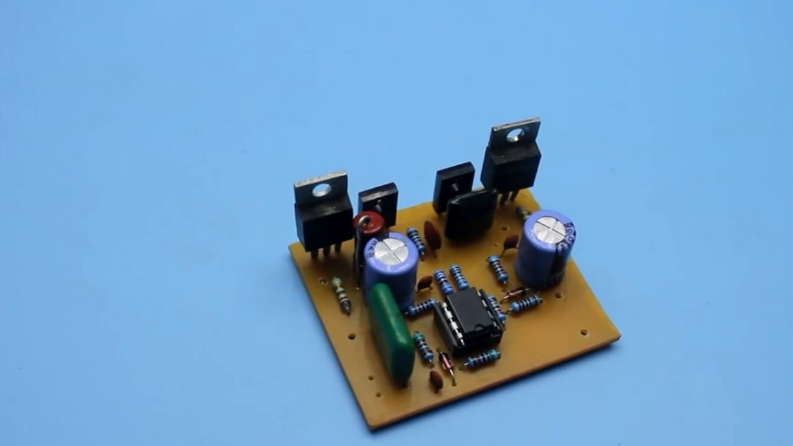
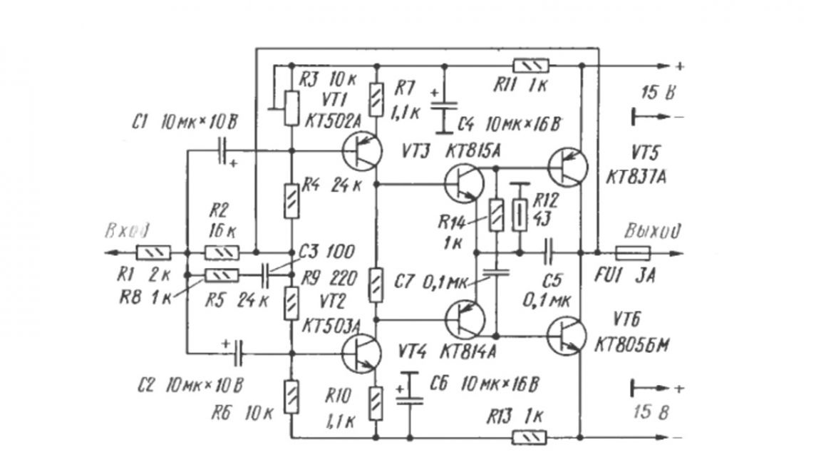
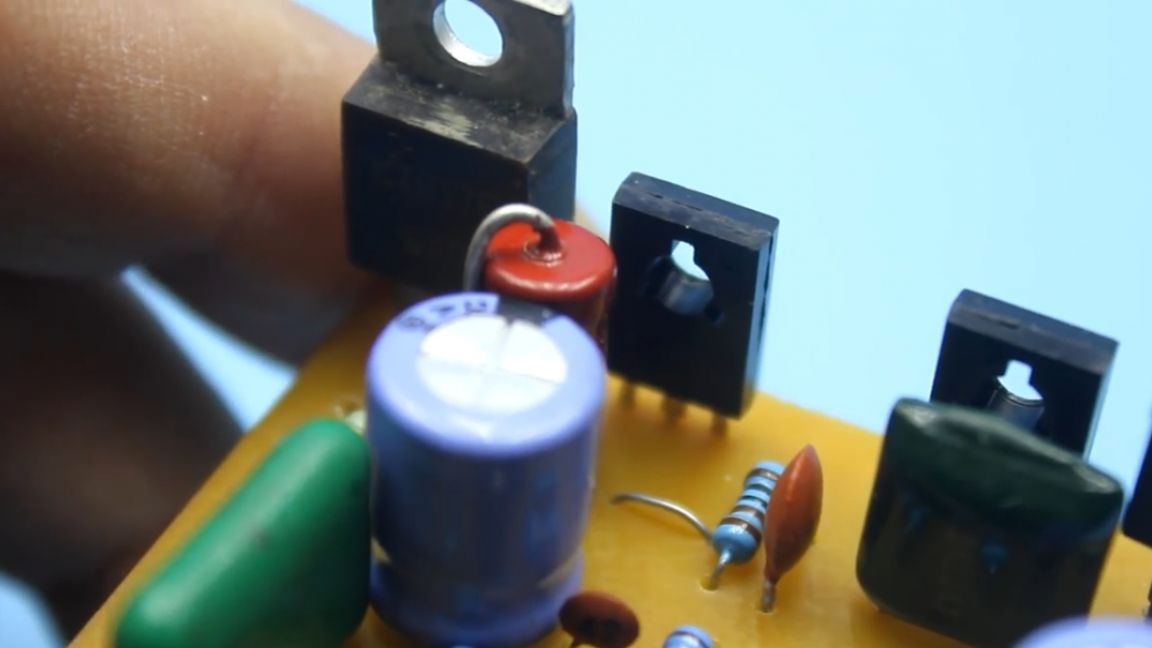
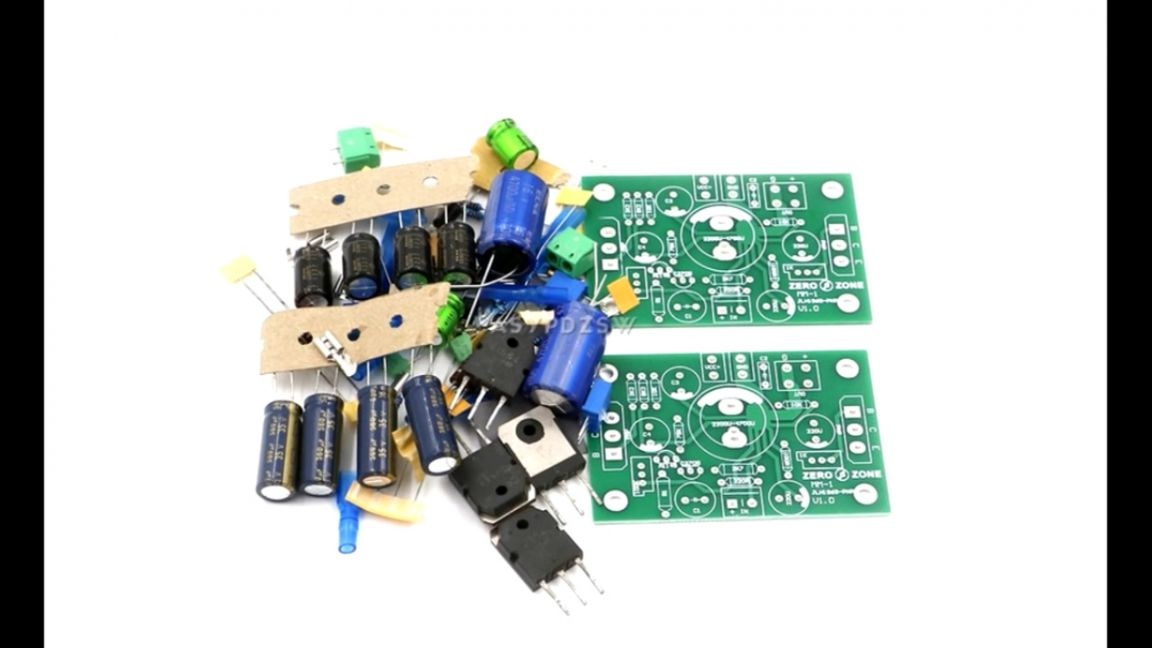
In case of replacement with other operational amplifiers, it is worth paying attention to the pinout, since the location of the terminals may be different. I advise you to install the operational amplifier on the socket of the solderless mounting, for quick replacement in case of something. By the way, this author has a second version of this amplifier, this time completely on transistors, it is now in front of you:
A few words about the printed circuit board, the master tried to make it as compact as possible, it seemed to work out pretty well.
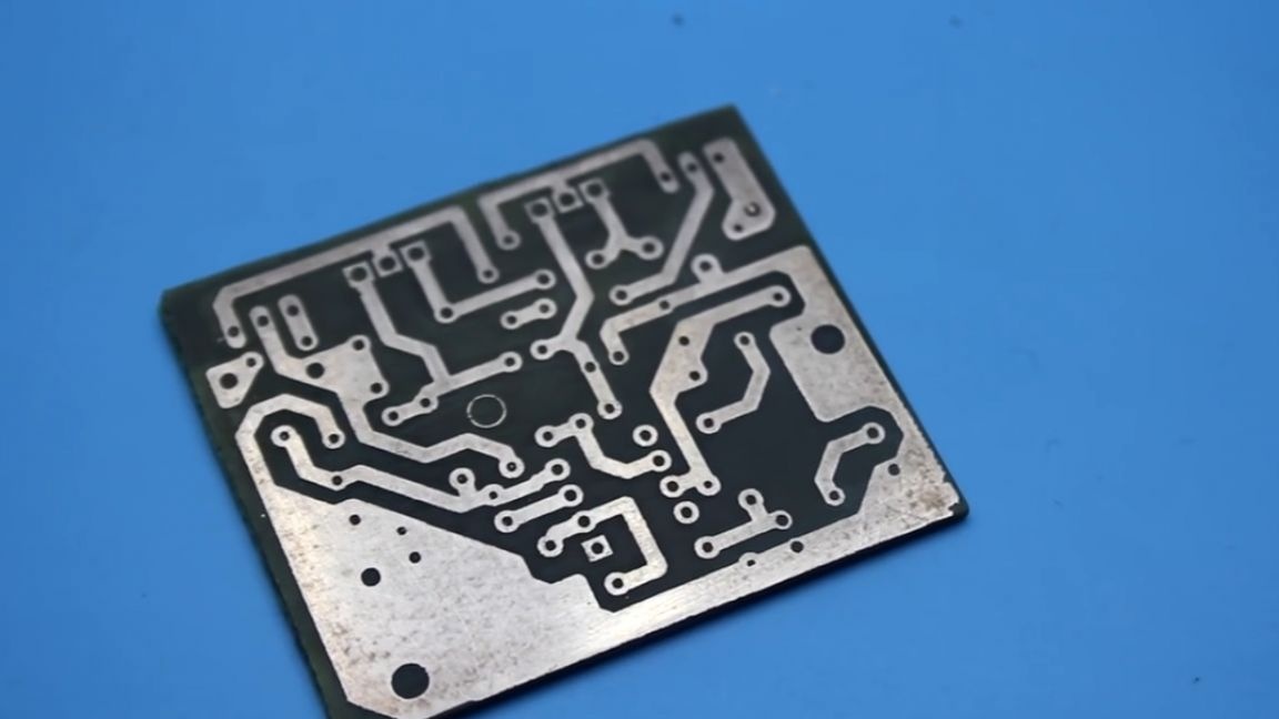
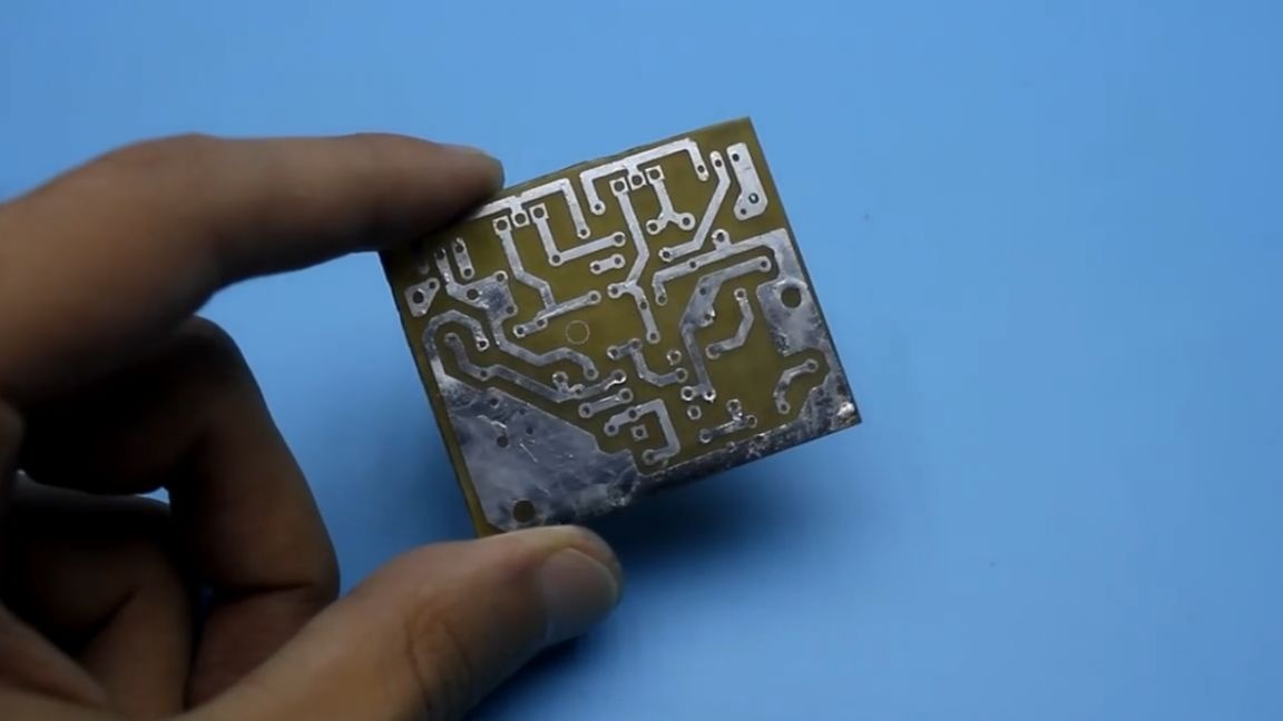
You will find the download link in the description under the author’s video (at the bottom of the page). There are jumpers on the board, it is advisable to solder them first.
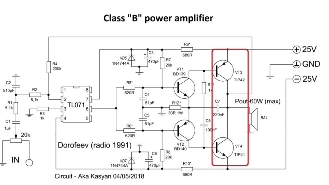
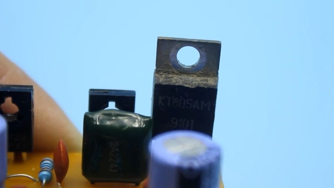
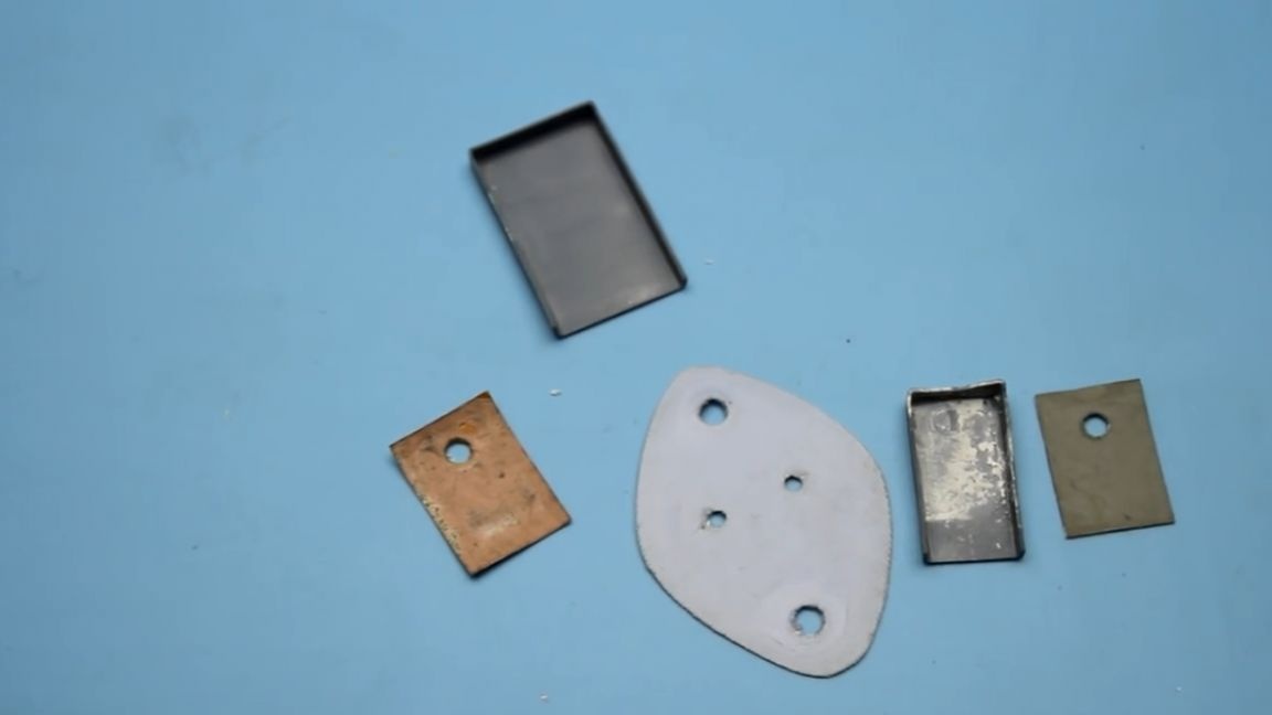
Transistors of the pre-output and output stages are installed on a common heat sink. Naturally do not forget to isolate them from the radiator.
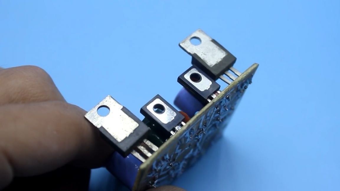
In the output stage, it is worth using transistors with a dissipation power of at least 50-60 watts, with a collector-emitter voltage of at least 60 V, and preferably 80 or 100 V, but here it also depends on the supply voltage.
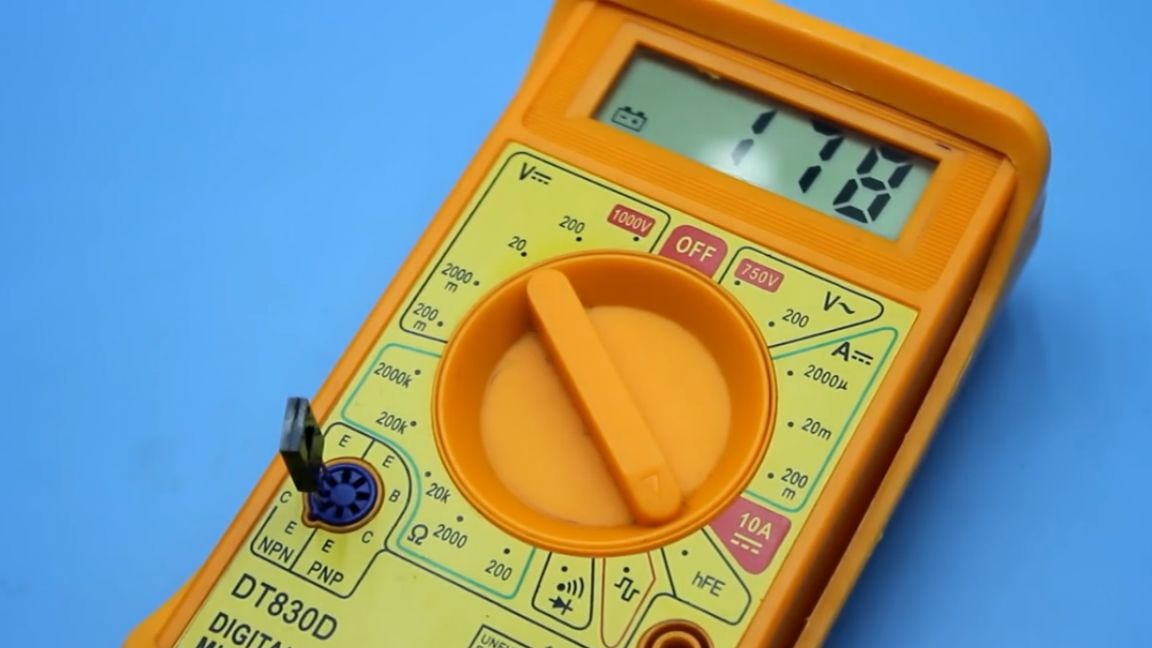
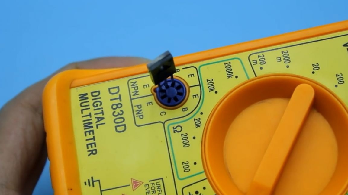
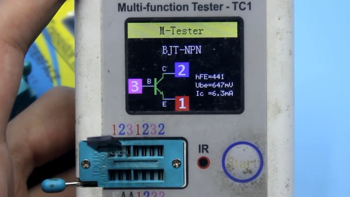
As can be seen from the diagram, in the output and output stages, complementary pairs of transistors are used. It is very, very advisable to select transistors for gain. Some multimeters have the function of checking this parameter, but you can use a transistor tester.

Zener diodes can be 0.5 W, with a stabilization voltage of 14 to 18 V.
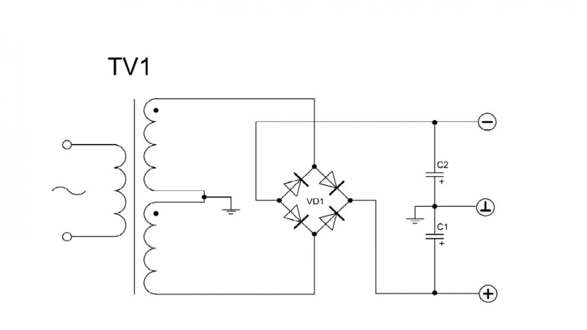
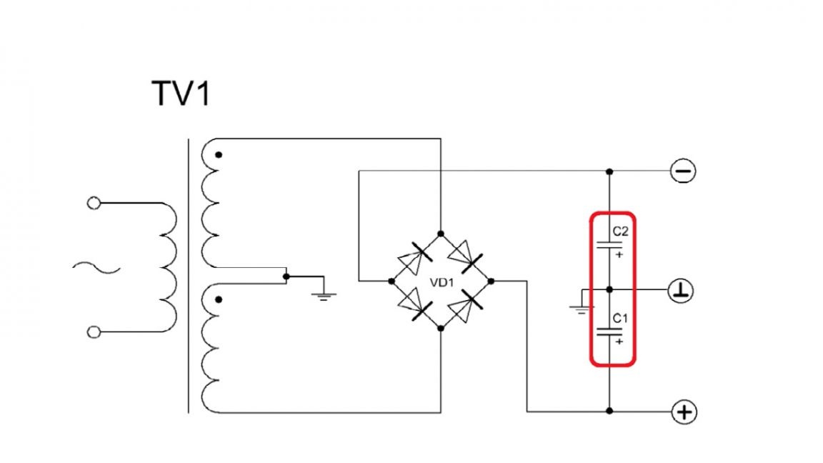
A few words about the power source.
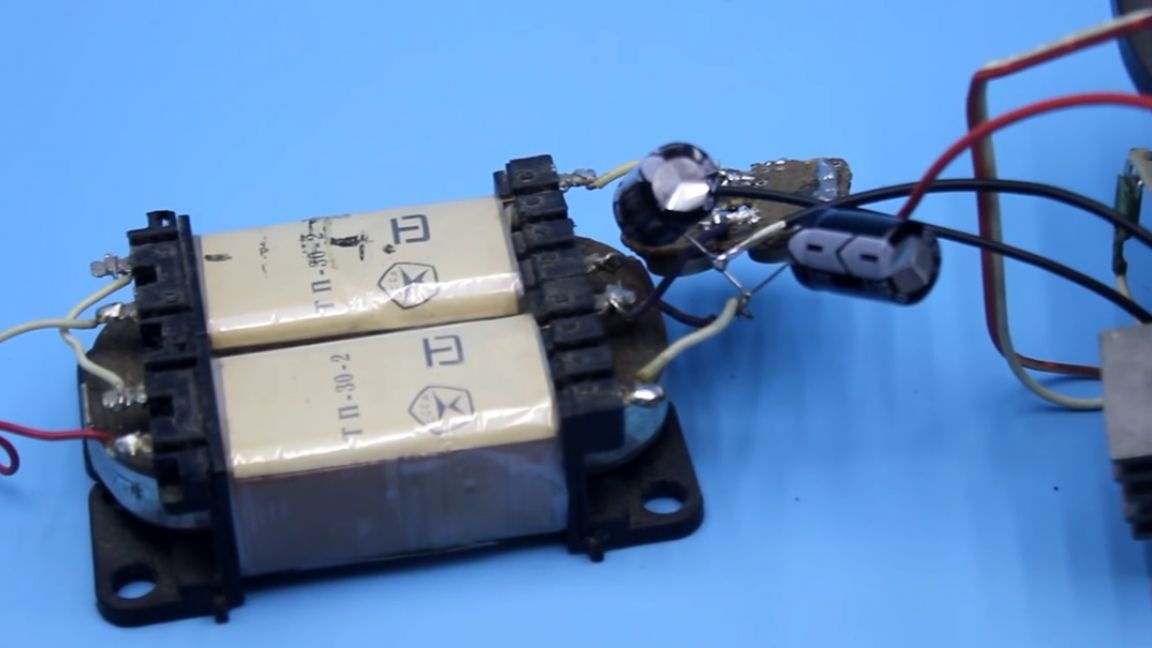
In the case of a transformer power supply, it is desirable to use filtering capacitors with a capacitance of at least 4700 μF, the more the better.
The amplifier works in class b and efficiency at a fairly high level, but in any case, the power source is needed with some margin. Therefore, it is necessary to take a transformer with an overall power of 70 watts. You can find out how the amplifier sounds by watching the author’s video. I must note that during the tests a certain background will be heard, this is due to the fact that the author of the project uses very small capacitors in the power supply unit, only 1000 microfarads in the shoulder.
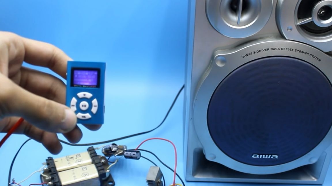
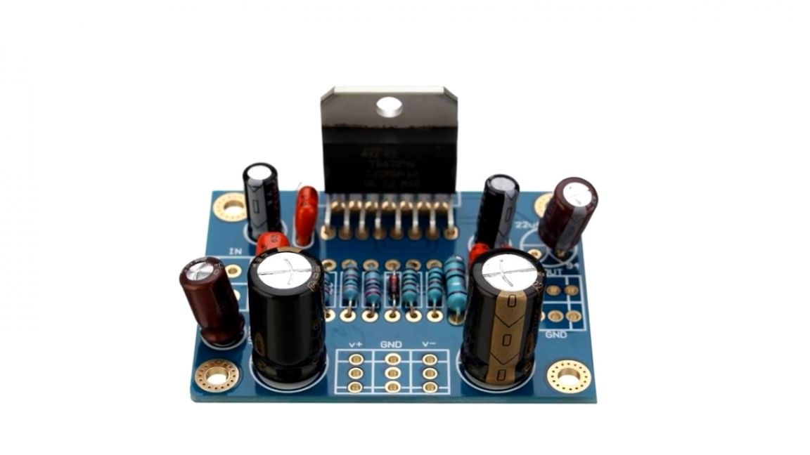
The quality, in principle, is good, at the level of TDA2030 microcircuits - 2050. With a good power source both in power and quality, it can quite compete with microcircuits like TDA7294.
That's all. In the description below the video, in addition to the project archive with the circuit and the board, you will find links to components for assembling the same amplifier, as well as to ready-made low-frequency amplifier boards for every taste.
Thank you for attention. See you soon!
Video: