
Hello to all lovers homemade. In this article I will tell you how to make a laser harp do it yourself, in the assembly of which the kit kit will help, you can order it by the link at the end of the article. This kit kit will be useful for both beginners and those who have been engaged in radio electronics for a long time, and such a radio constructor will be of interest to children for entertainment.
Before proceeding to read the article, I suggest watching a video with a detailed assembly of this kit, as well as testing it in real conditions.
In order to make a laser harp with your own hands, you will need:
* Soldering iron, flux, solder
* Device for soldering "third hand"
* Side cutters
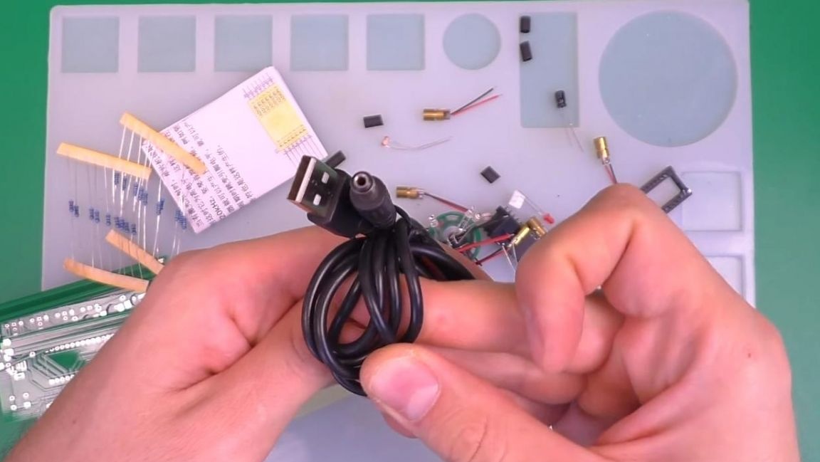
* Power supply with USB output
* Multimeter
Step one.
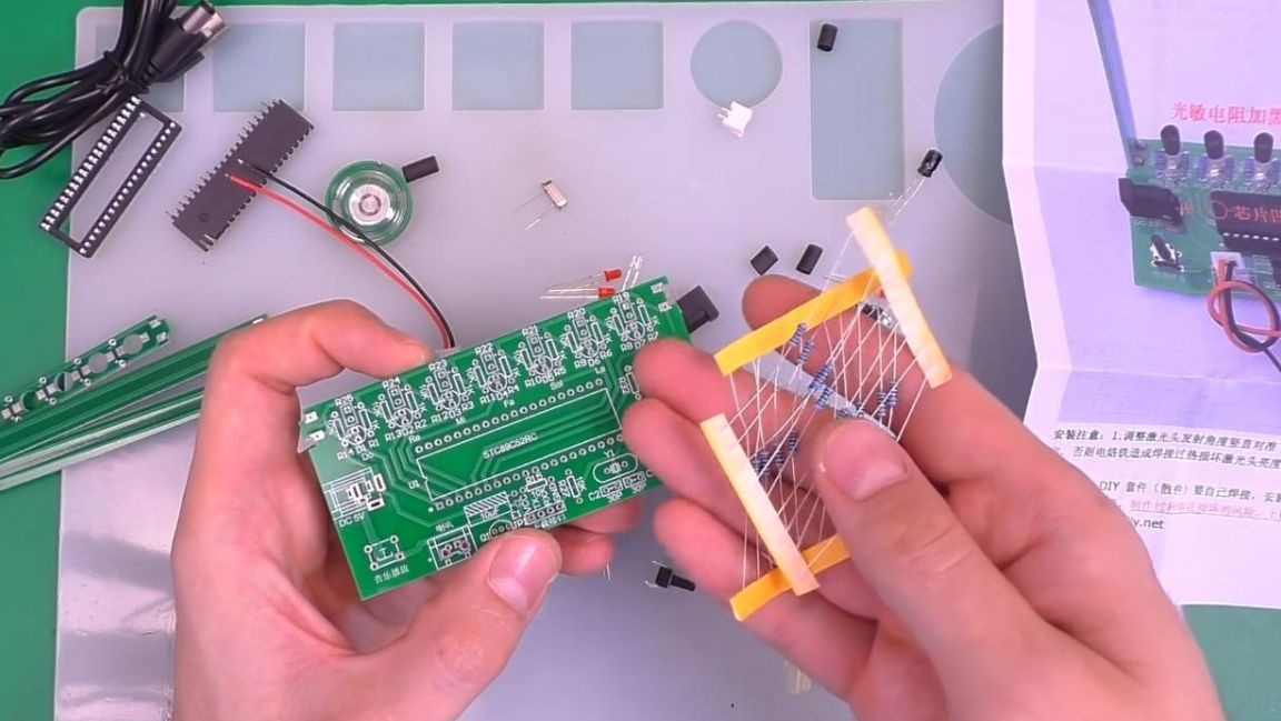
To begin, consider the kit kit. There are a lot of components, for example, LEDs, resistors, transistors, power wire and others.
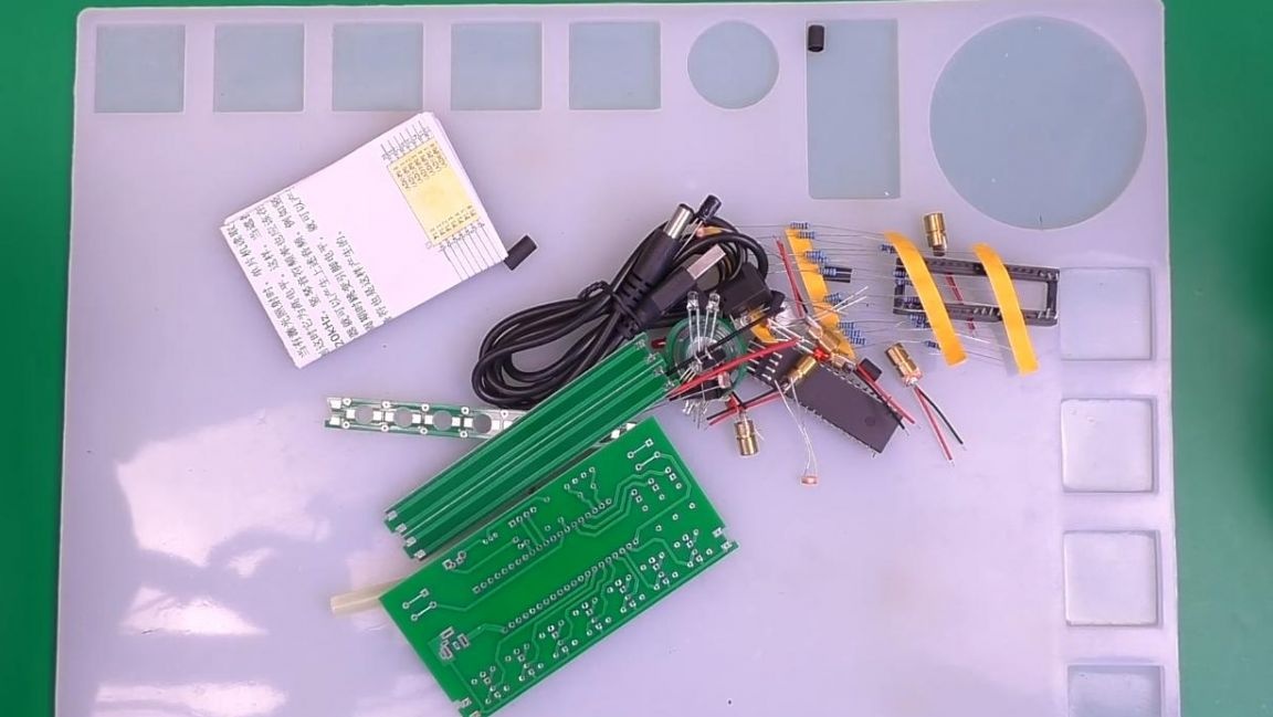
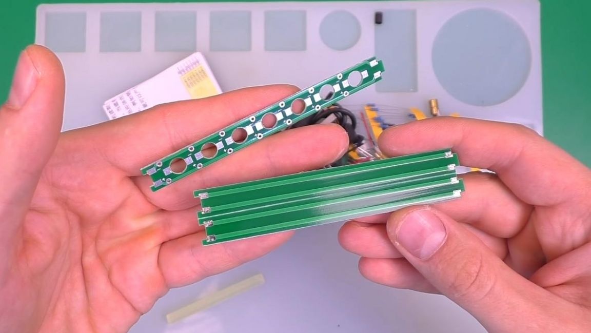
The principle of operation of the harp is based on the interruption of the laser beam, thereby including a certain note, three boards are designed for their installation, two of which need to be broken in half in the mark.
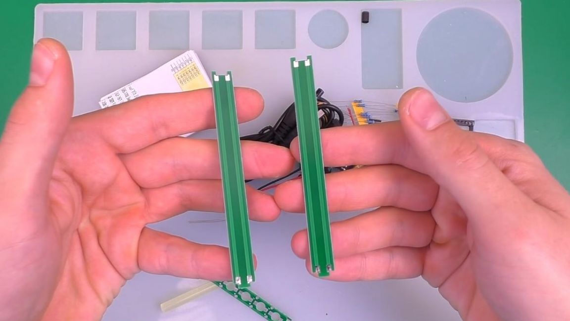
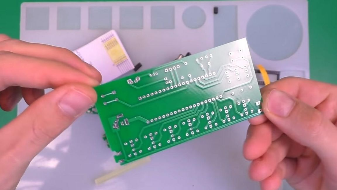
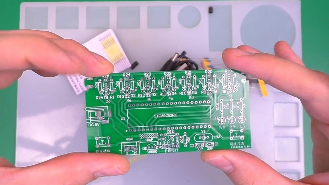
There is also a double-sided printed circuit board with metallized holes and the markings indicated on it, the workmanship is good.
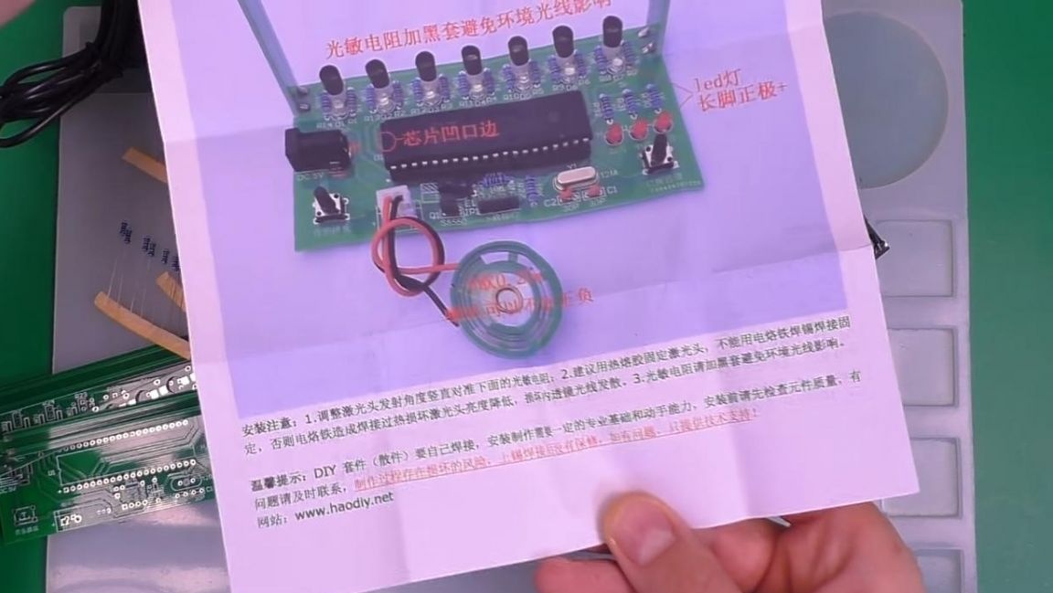
For ease of assembly, the kit contains instructions that depict a diagram and a picture of the finished kit.
Step Two
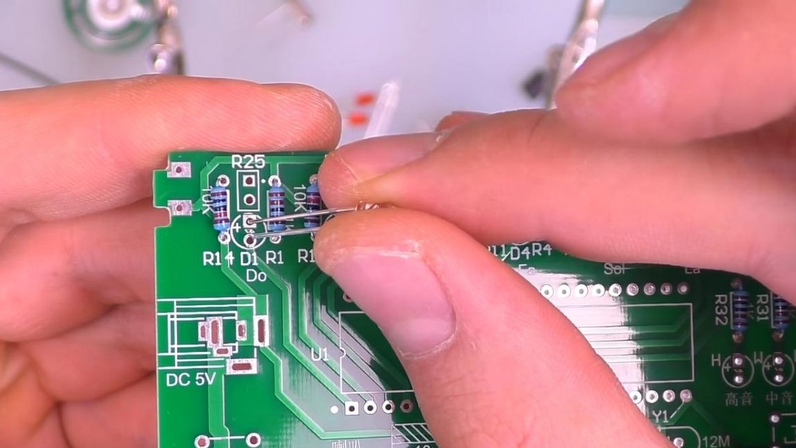
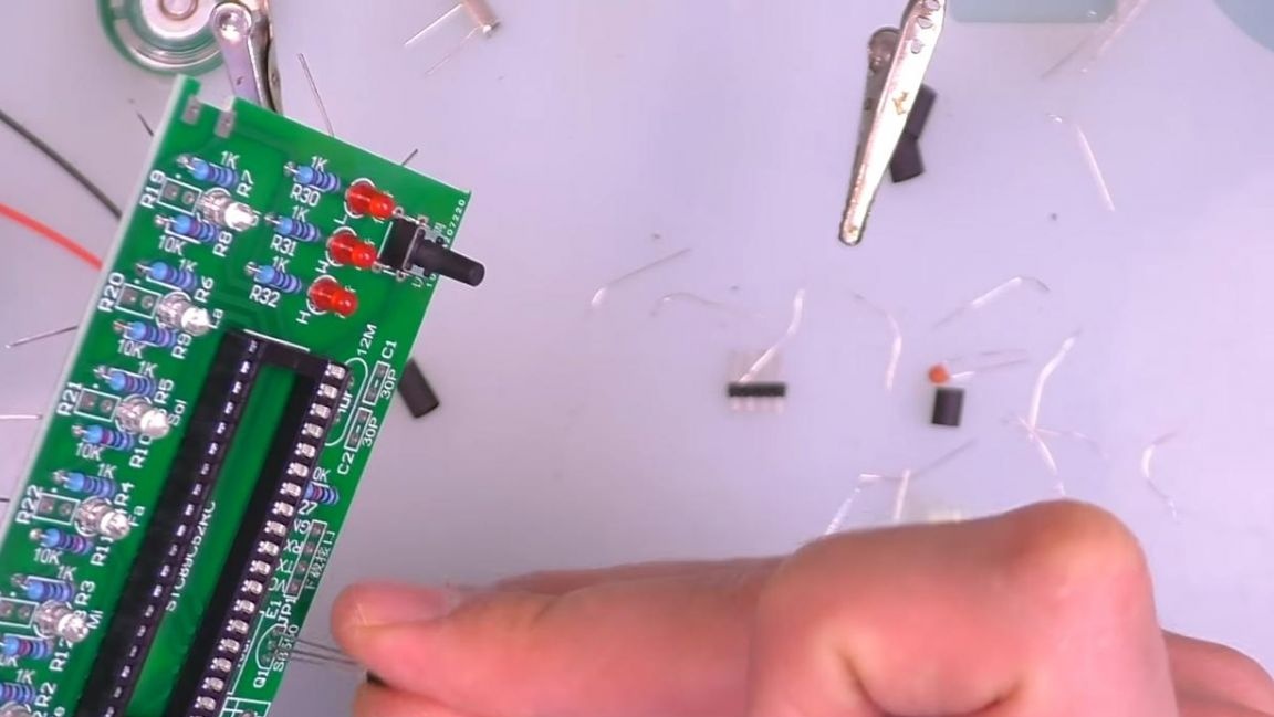
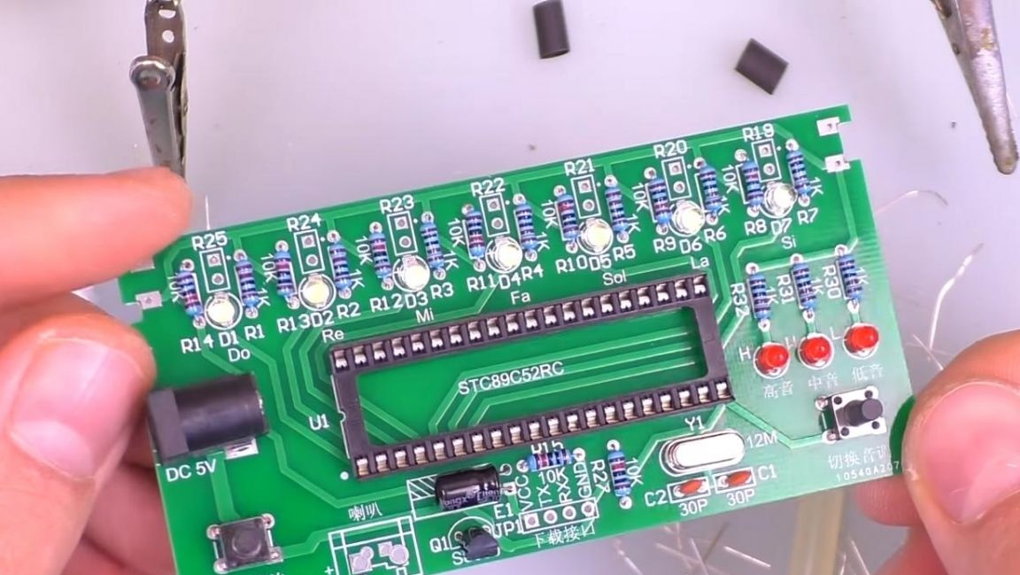
We begin the assembly traditionally by installing resistors on the board.
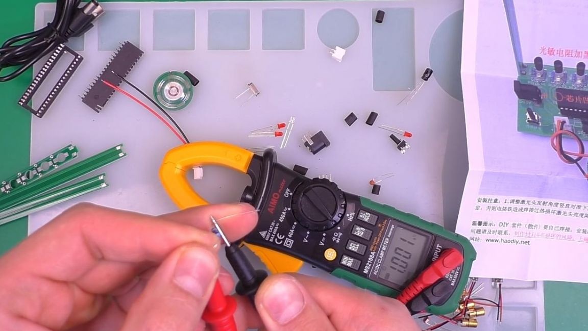
Before installing resistors, you need to find out their nominal resistance, you can do this with a multimeter, a lookup table and color coding, as well as an online calculator.
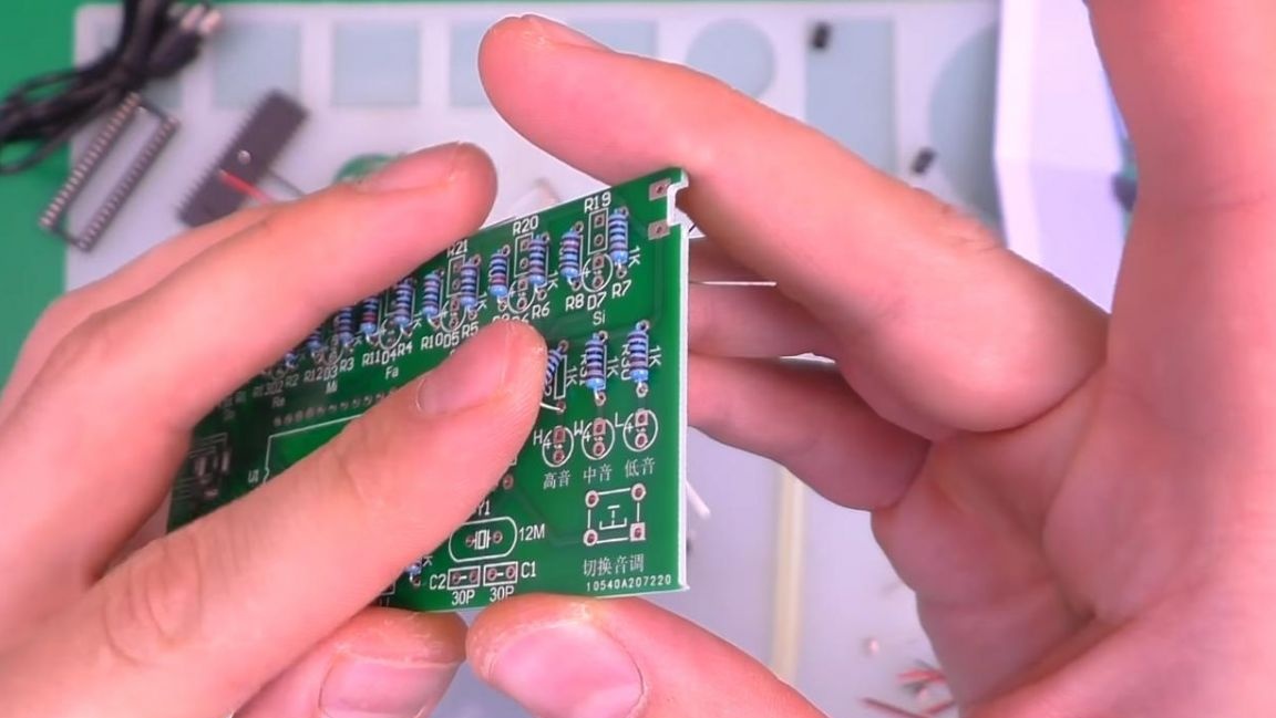
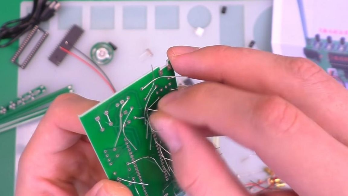
Having determined the resistance of each resistor, we insert them into their places according to the marking on the board, on the back side of the board we bend the leads so that the radio components do not drop out when soldering.
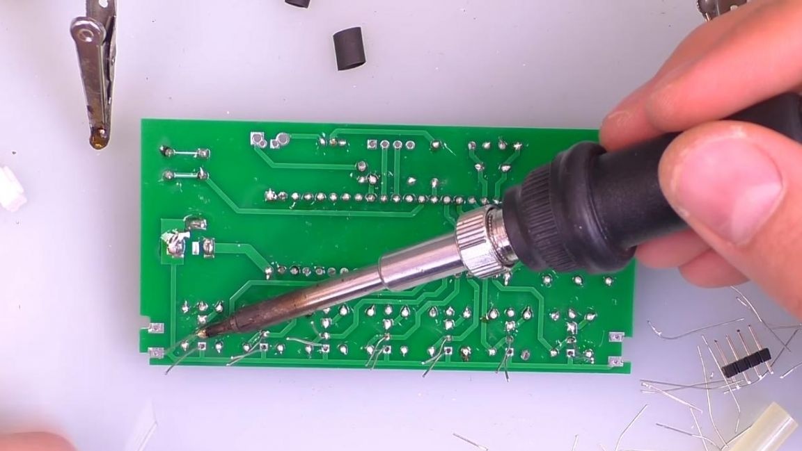
Next, fix the board in the third-hand soldering device and apply flux to the board contacts, then solder them with a soldering iron and solder.
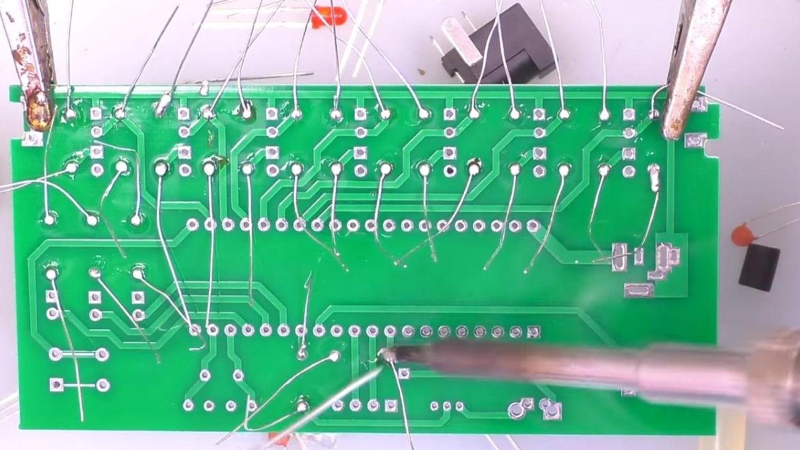
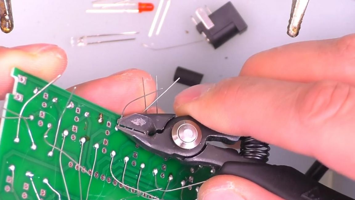
After soldering, remove the extra parts of the terminals using side cutters. When removing pins with side cutters, be careful as you can tear the track off the board.
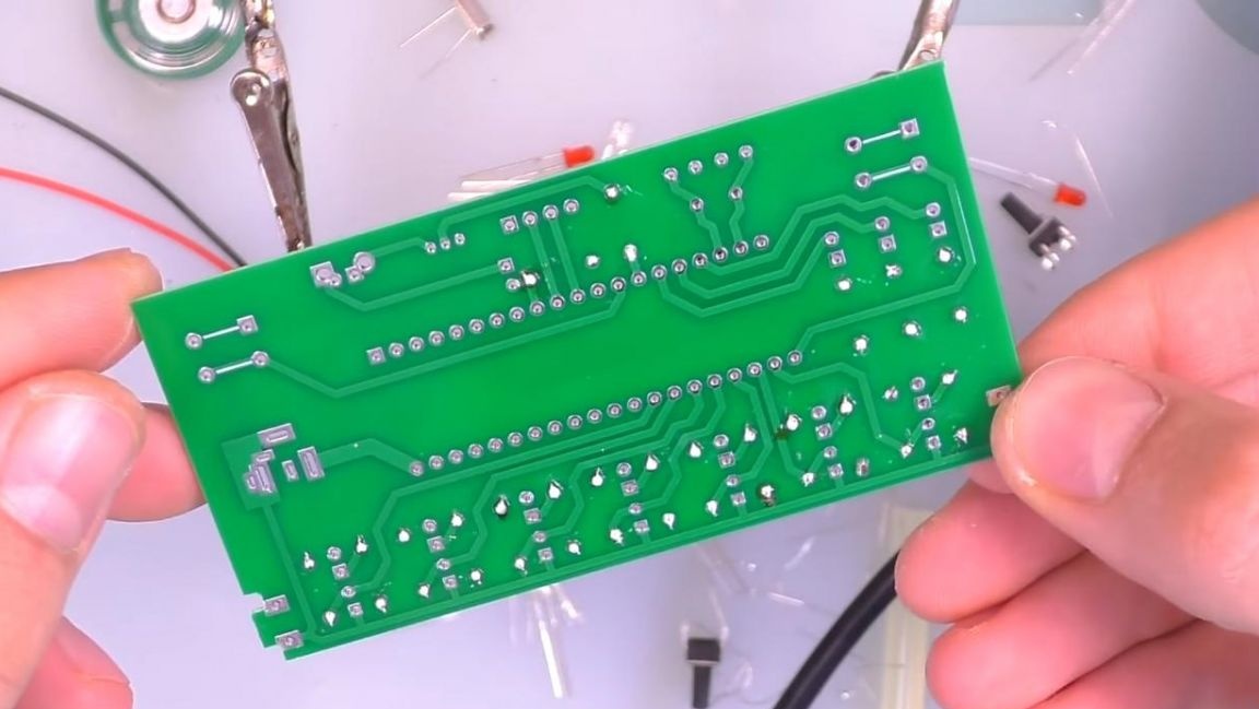
The result is such a board with cropped legs.
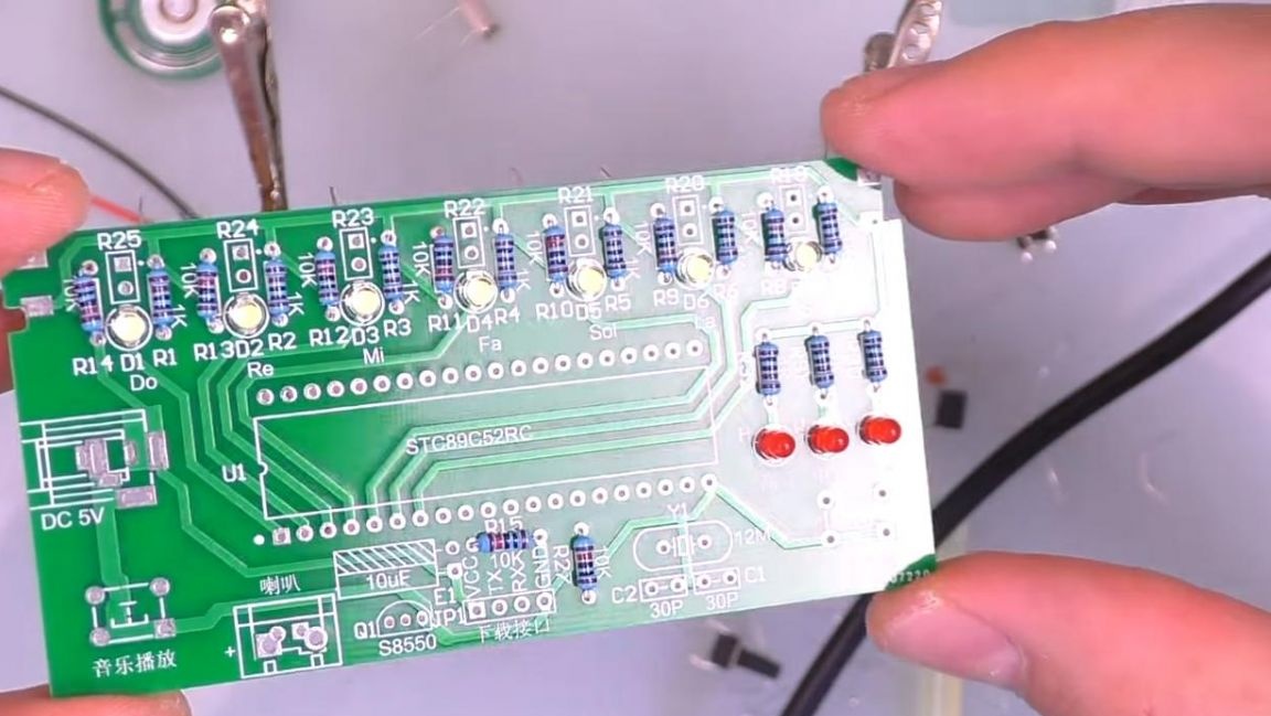
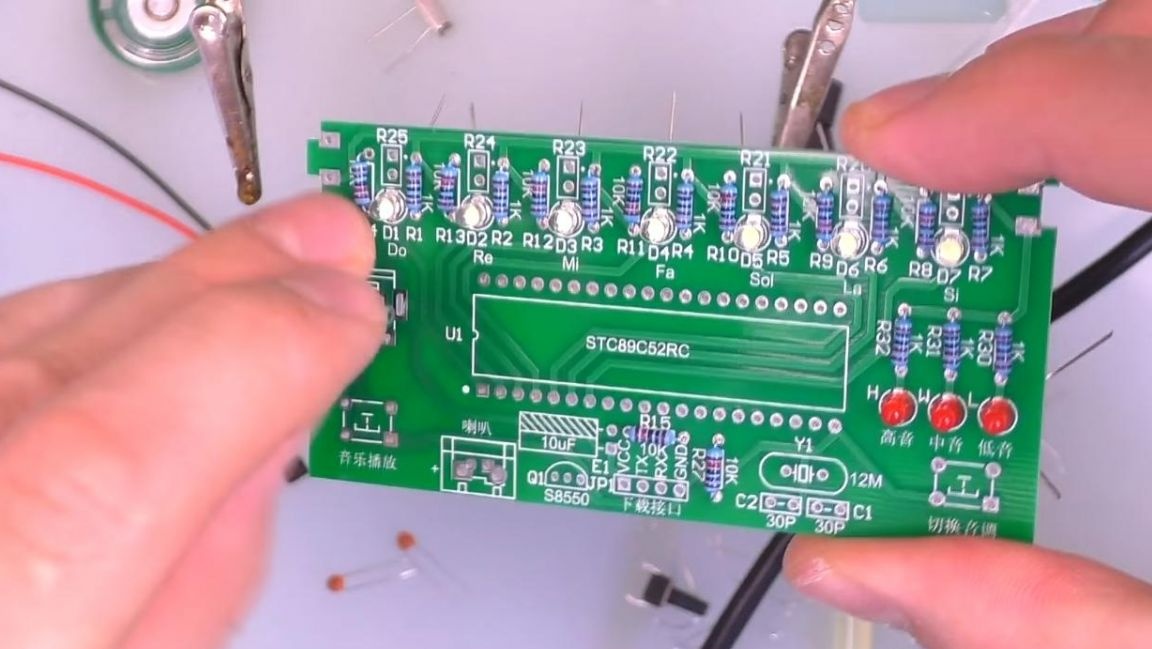
Step Three
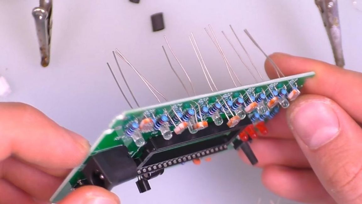
Next, we install white LEDs on the board, their positive output is the long leg, and the negative is short, the polarity is indicated on the board, and the plus contact has a square shape.
In the bottom row we insert three red LEDs, they are responsible for indicating the selected key.
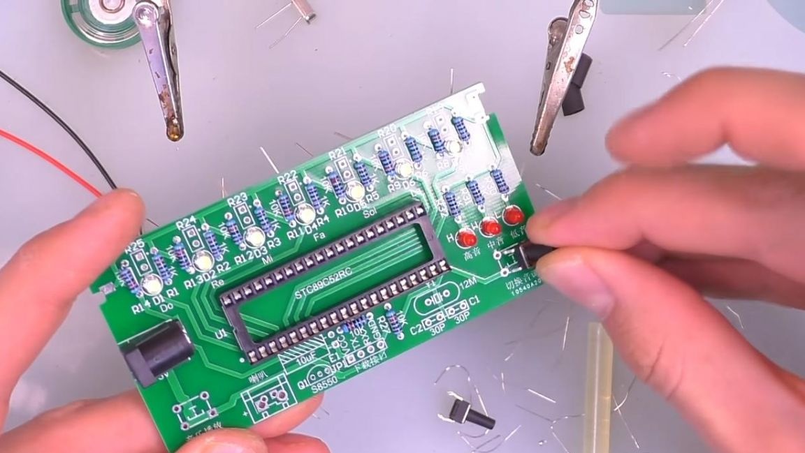
Then we insert the power socket, the socket for the microcircuit, focusing on the key on the board and on the case. Also, to change the tonality and demonstrate the music, we install two buttons.
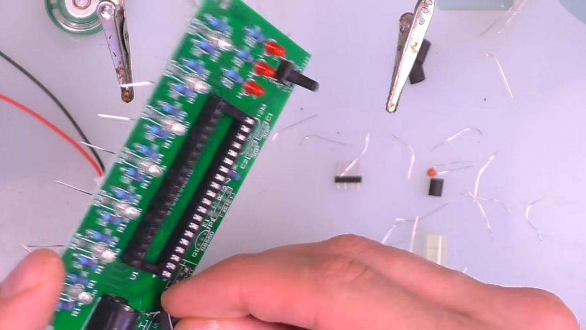
After that, we put the transistor in place, focusing on its shape indicated on the board.
Step Four
Now we insert ceramic non-polar capacitors, as well as quartz.
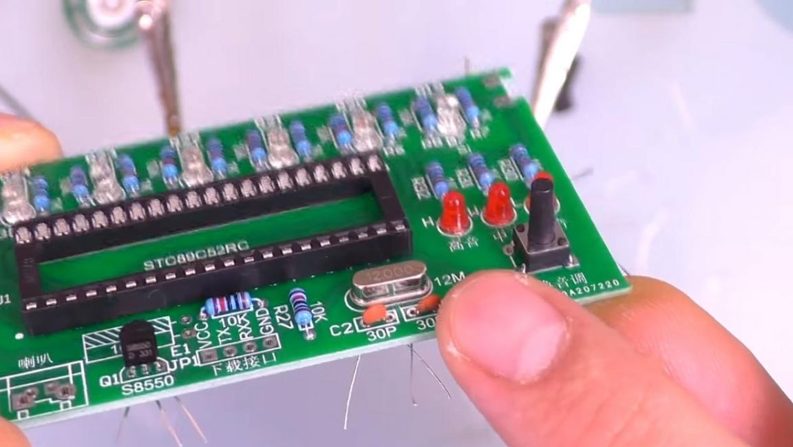
Then the electrolytic polar capacitor, its long leg is a plus, opposite the negative contact there is a white strip on the case, on the board the minus is indicated by the shaded part.
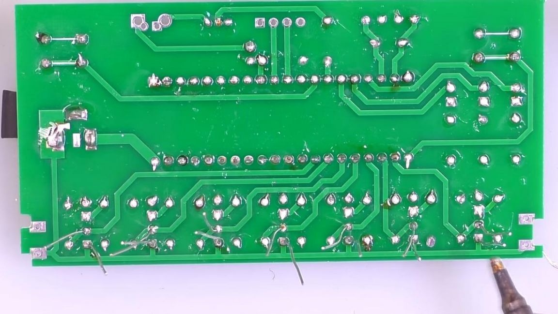
We fix the board in the “third hand” device and solder all the terminals of the radio components, apply flux for better soldering, then remove the rest of the legs.
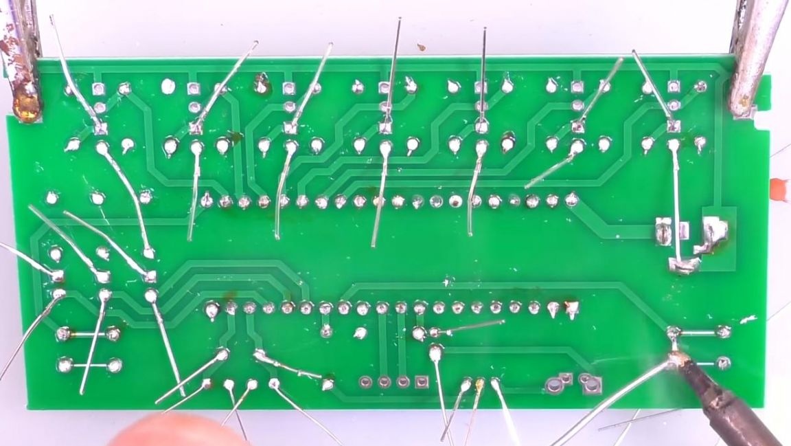
This is how the board looks after soldering on the front side.
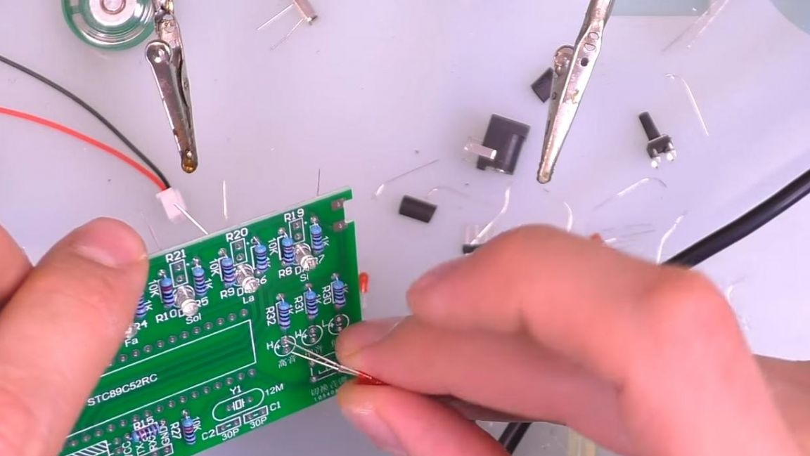
Step Five
It's time to put the photoresistors, they do not have polarity. We approximately set the same departure of the photoresistors relative to the board and solder one of the two contacts.
Next, we correct the photoresistors and finally solder their second conclusions.
After soldering the connector for microcontroller firmware, if necessary.
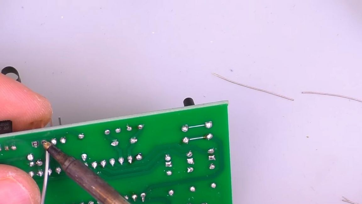
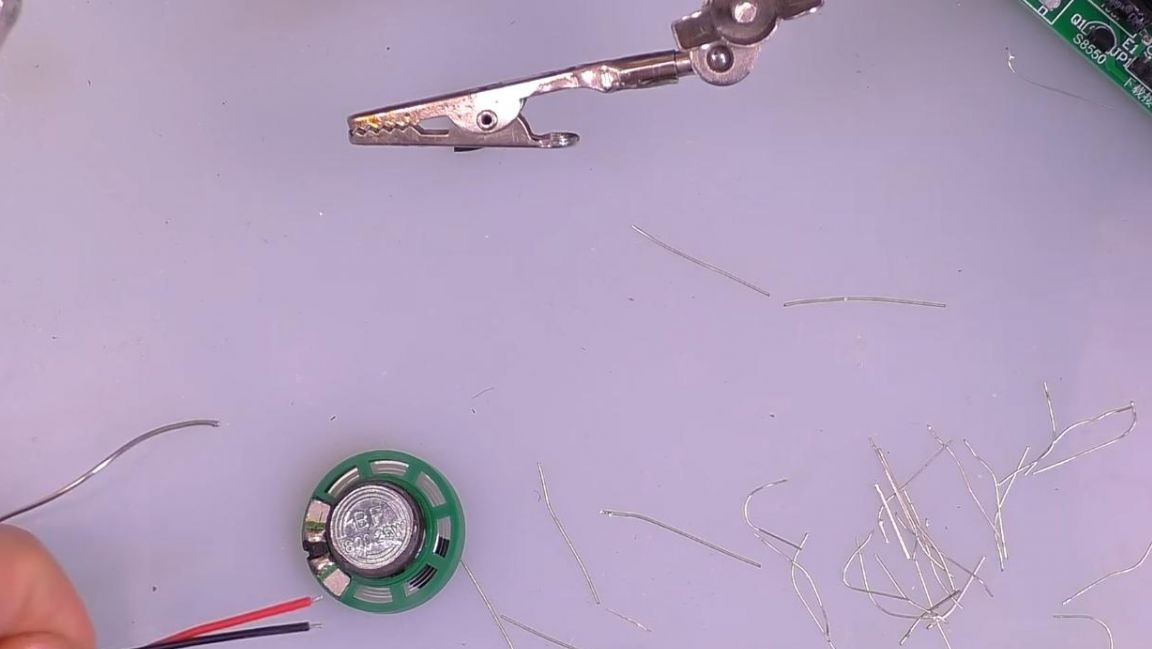
Then solder the speaker connector.
The bottom of the board is ready, now let's move to the top.
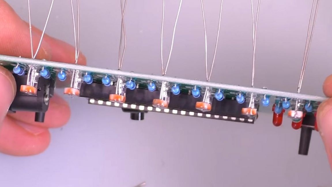
Step Six
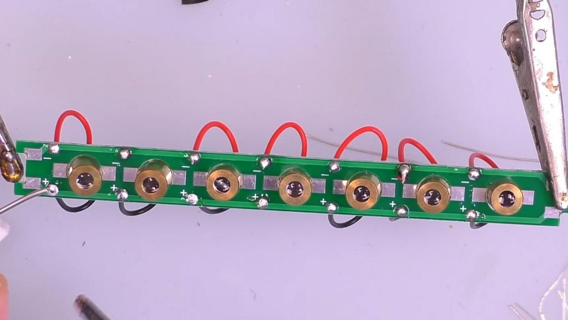
We install lasers in the holes of the printed circuit board and insert the wires according to the polarity.
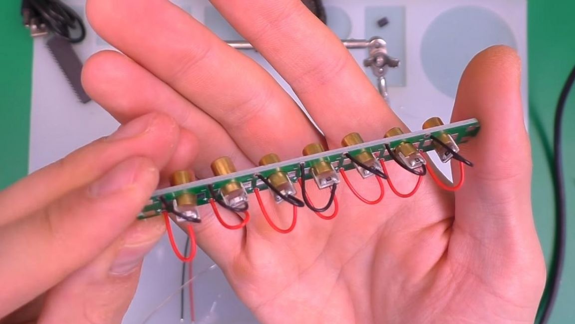
Next, we solder the wires going from the laser to the board, installing it in the soldering device "third hand", as well as the wires to the speaker.
Then install the rest of the board and solder to the main one.
After soldering, we fix the lasers on the board, since hot glue was included in the kit, then we fix them with it.
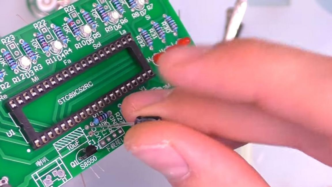
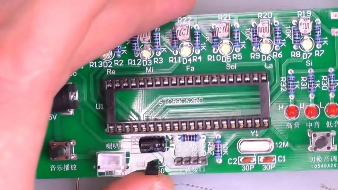
Now we install the microcontroller, focusing on the key in the form of a recess on the housing and on the socket.
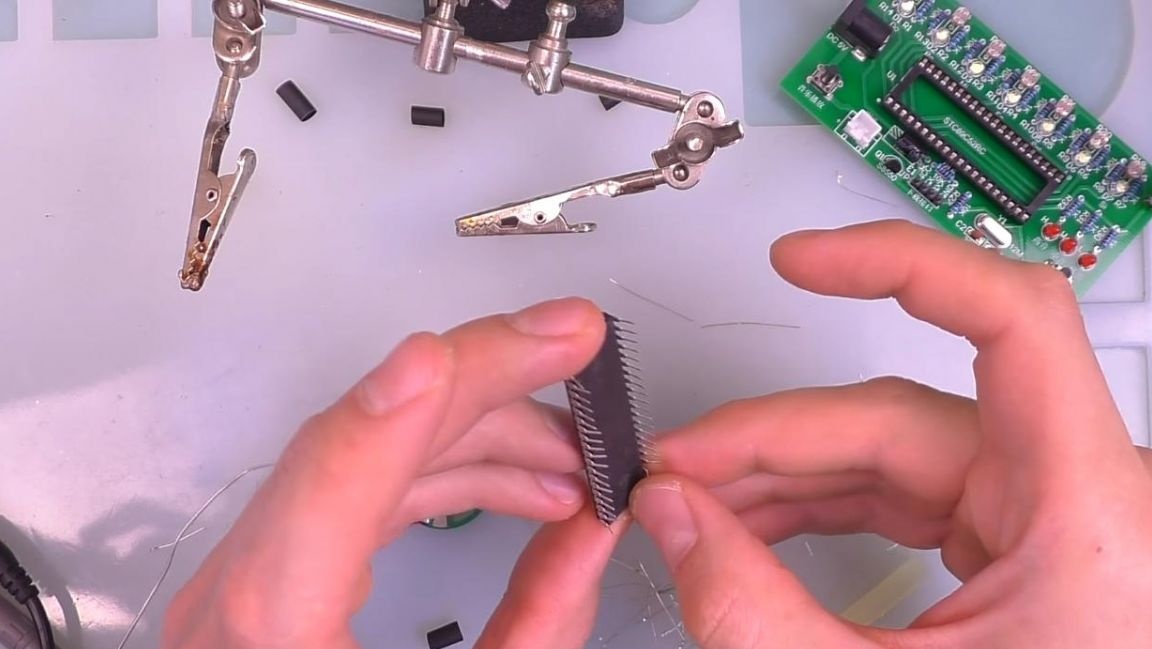
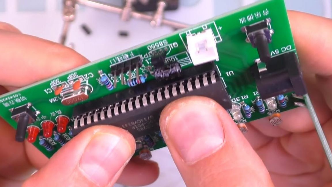
During transportation, the terminals of the microcontroller are slightly bent, but they are also easy to straighten to their original position.
The circuit is fully assembled, which means it's time to test it in work.
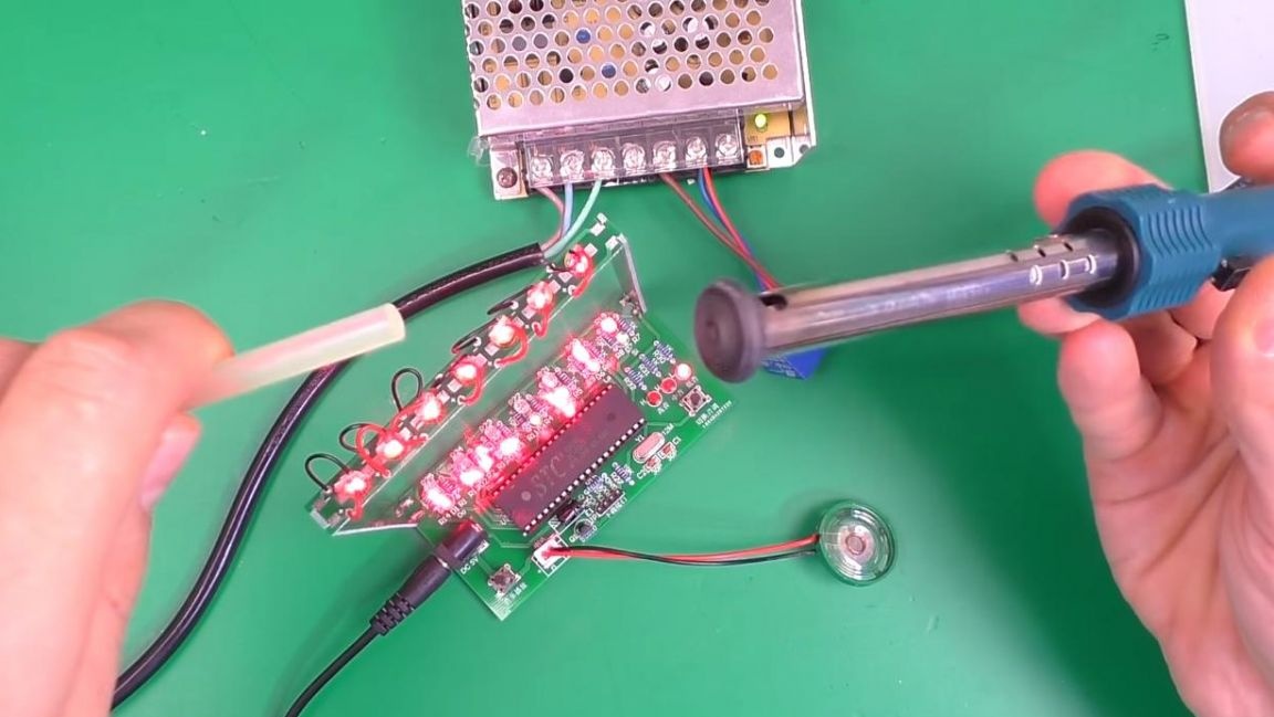
Seventh step.
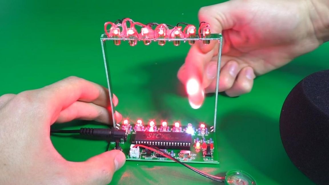
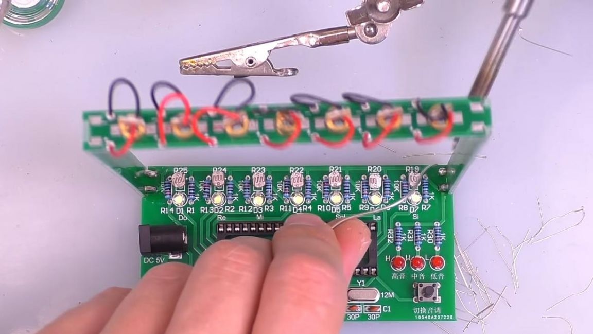
We connect the power supply to the finished kit kit and check its operation. As it turned out, the position of the lasers was initially not perfectly smooth, so later they had to be slightly corrected so that they would exactly hit the photoresistor. After these manipulations, the laser harp worked as it should. When the laser beam is blocked, the LED that is next to the note lights up and the speaker reproduces the sound of this note.
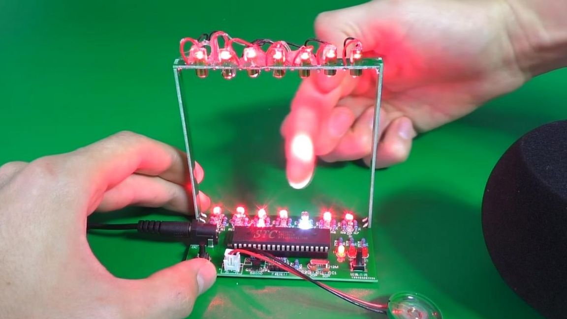
The tone can be changed using the right button, and to play the music "wired" into the microprocessor, just click on the left button. Such a harp will be a great entertainment for the child, and the assembly process itself will drag every lover of radio electronics.
That's all for me, thank you all for your attention and creative success.