
Hello to all lovers homemade. In this article I will tell you how to make a pre-amplifier do it yourself, in the assembly of which the kit kit will help, a link to it will be at the end of the article. This radio designer is intended for radio amateurs, as well as those who want to try their hand at making a pre-amplifier, well, and then use the finished pre-amplifier in the speaker system.
Before you read the article, I suggest watching a video with a detailed assembly of the kit, as well as checking it.
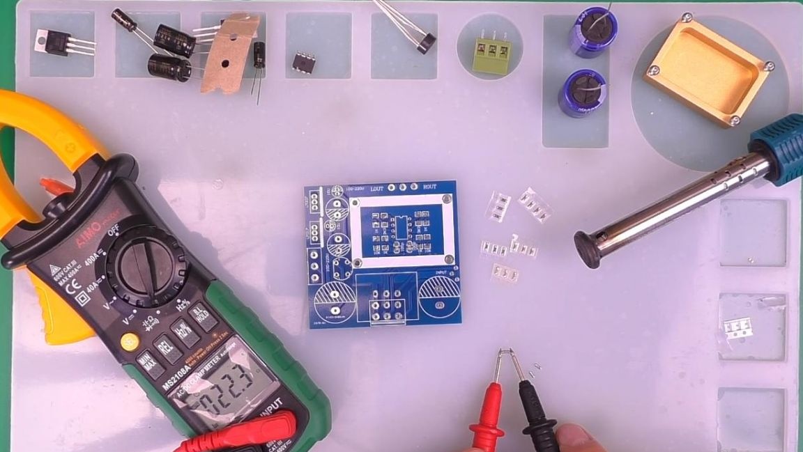
In order to make a pre-amplifier with your own hands, you will need:
* Kit
* Soldering iron, flux, solder, solder paste
* Soldering hair dryer or infrared soldering iron
* Multimeter
* Tweezers
* Side cutters
* Potentiometer, you can order
* Silicone soldering mat
* 12V power supply
* Phone or other playback device
* Headphone or amplifier with speaker to check
Step one.
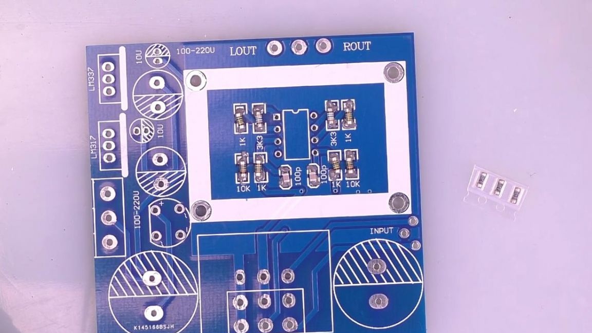
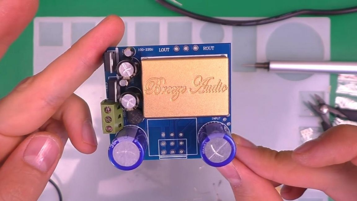
First, consider a kit kit. It has a double-sided board with metallized holes, the workmanship is quite high.
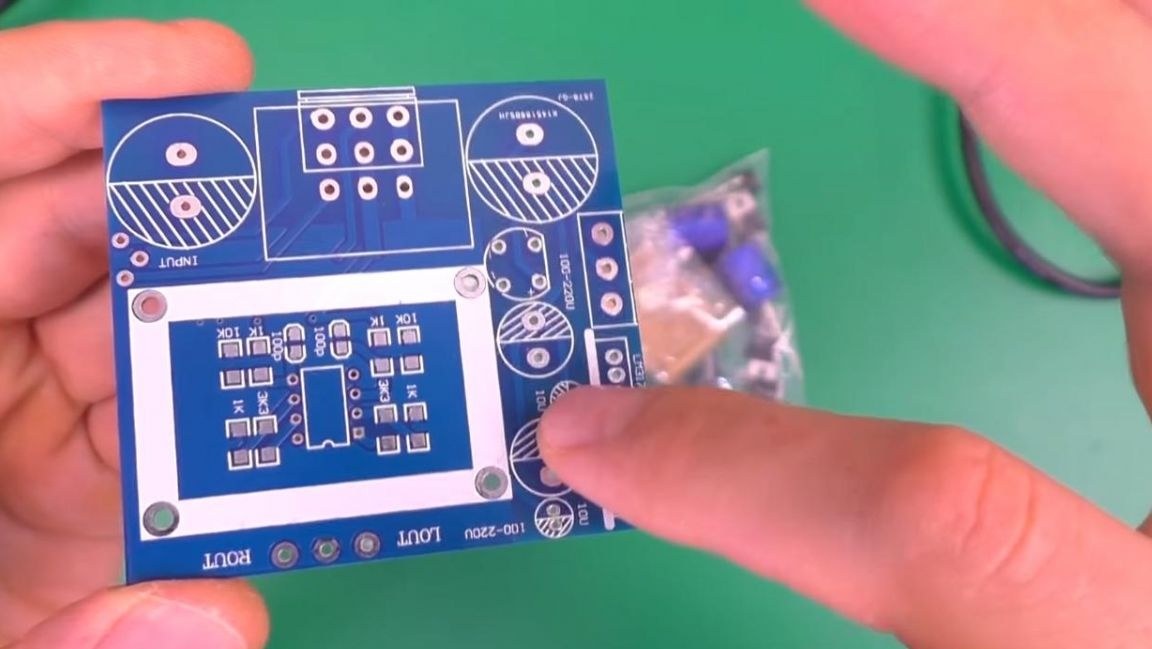
There is a marking on the board itself, which is convenient when installing radio components on it, and there is also a manual with a detailed diagram in the kit.
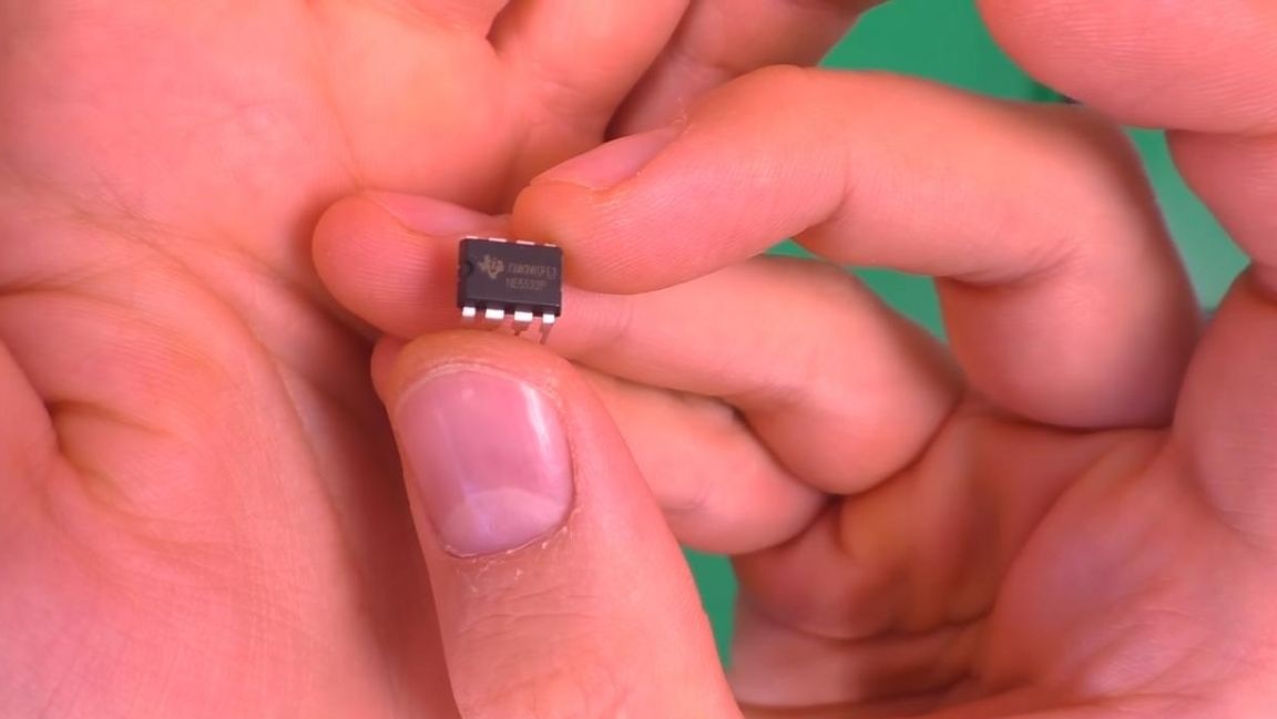
The preamplifier itself will work on the NE 5532P chip, which is widely used in similar kit-sets related to sound.
The rest of the kit has a bag with SMD components, as well as parts with leads, such as capacitors, a diode bridge, and so on.
Step Two
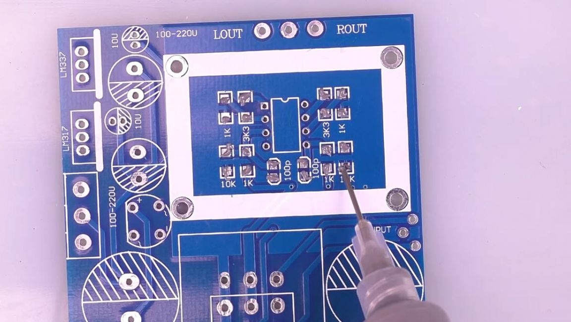
We place all the components on the silicone mat, this is quite convenient, since when assembling the board, the radio components are not randomly scattered around the table, but lie in a specific compartment. Next, using a gun and a tube installed in it, apply solder paste to the contacts under the SMD components. Using a gun in this case is very convenient, as it allows you to apply solder paste in batches and almost the same.
Then we pull out the SMD resistors from the tape and determine their resistance using a multimeter. If you do not have a multimeter, then you can measure the resistance of the resistor by color coding and a look-up table, as well as an online calculator.
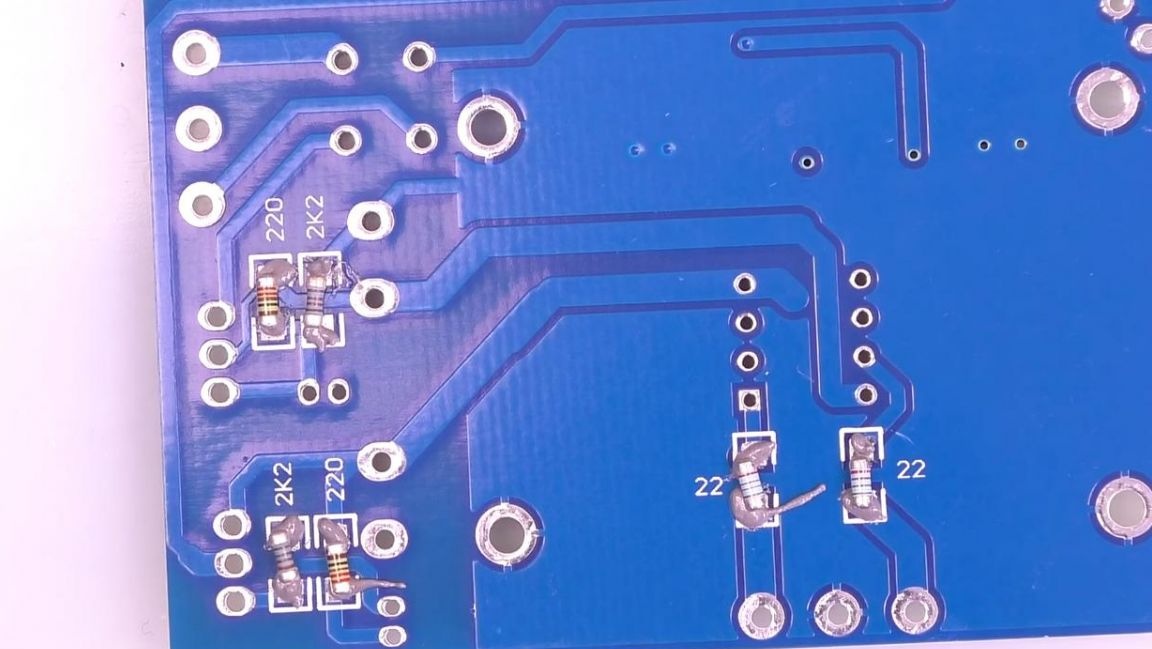
After that, using tweezers, we place the resistors on the board according to the marking. Similarly, we install ceramic non-polar capacitors on the board.
We heat the board with an infrared soldering iron and solder the SMD parts, if necessary, correct their position with tweezers.
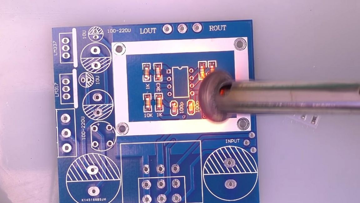
As a result, the soldered parts look like this.

Step Three
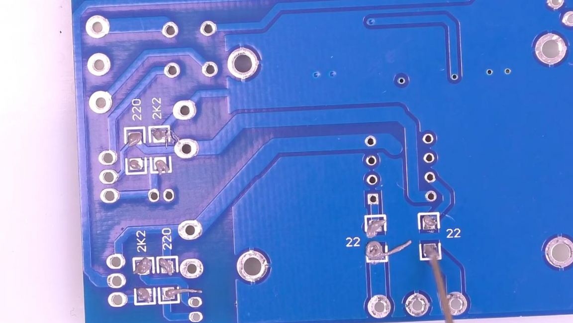
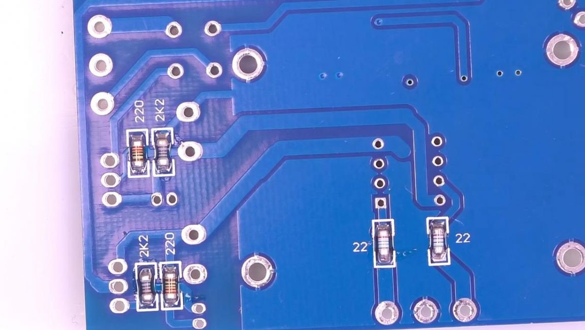
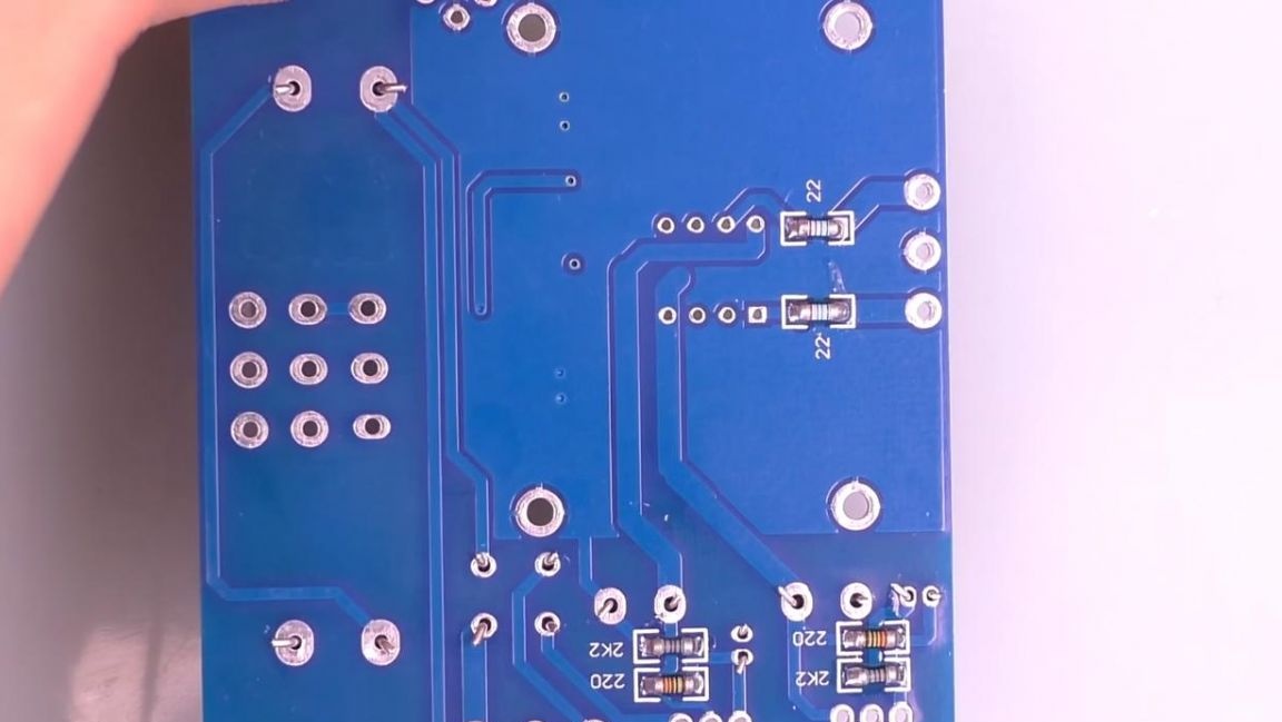
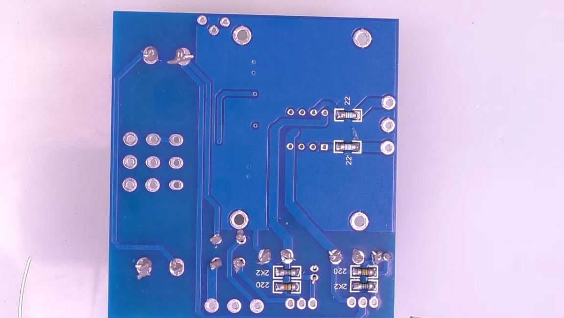
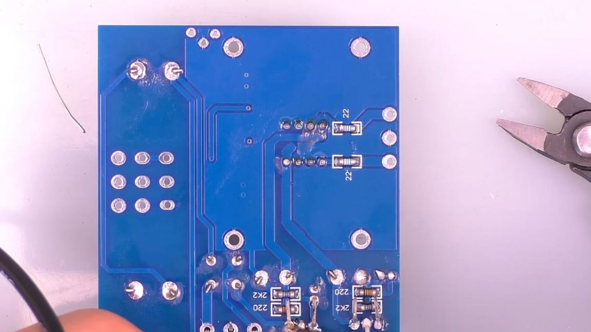
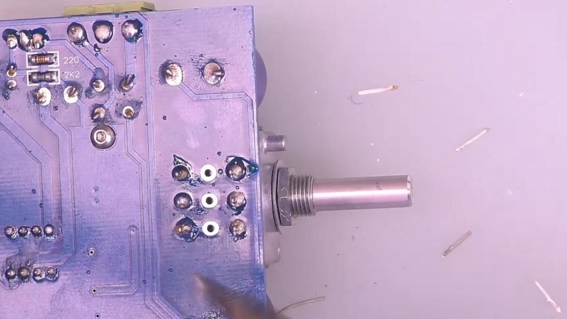
Now we turn the board over on the other side and apply the paste to the contacts, after which we install the SMD resistors according to the ratings and solder in the same way as in the previous step.
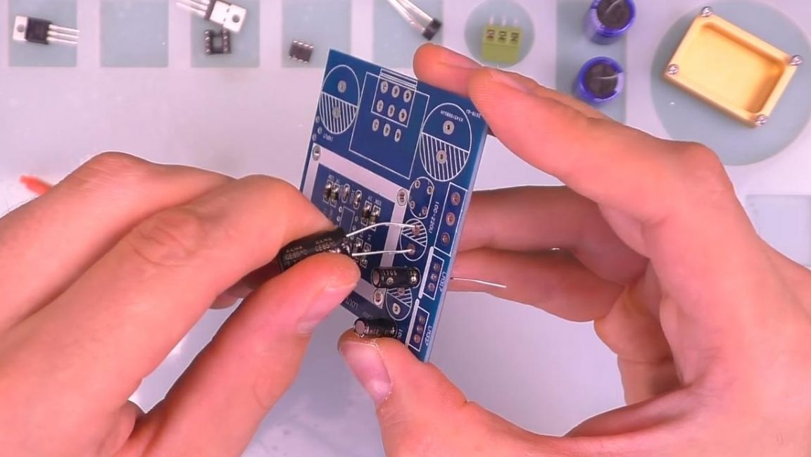
Next, we install electrolytic capacitors, observing the ratings and polarity. The long terminal of the capacitor is a positive contact, on the case there is a white strip opposite which there is a negative terminal, on the board it is indicated by a shaded semicircle. In order to prevent radio components from falling out during soldering, we bend their conclusions from the back.
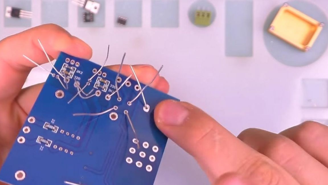
After that, using the side cutters, we remove the excess parts of the legs. When removing the terminals with side cutters, be careful, as you can easily damage the board's track or even tear it off.
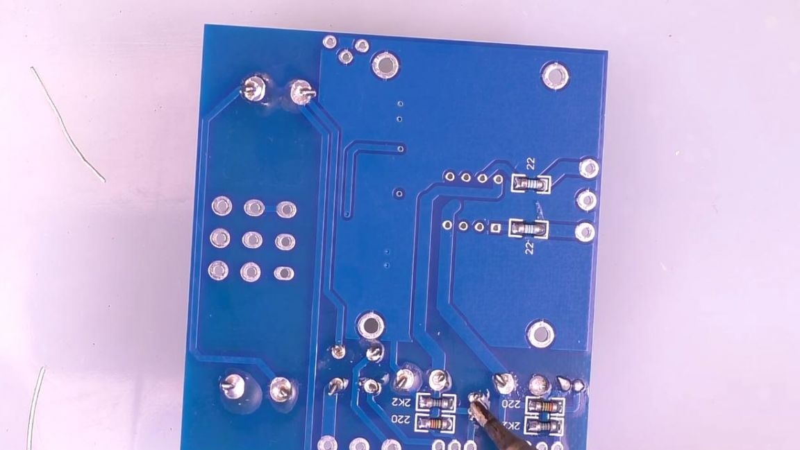
Next, apply solder paste with a gun and solder the contacts with a soldering iron, adding solder as needed.
Step Four
We install stabilizers in their places, being guided by the marking, the metal part should be on the side of the thick line shown on the board, for convenience we will bend their legs so that they do not fall out when soldering.
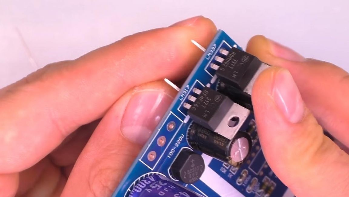
Then we insert the power connector, a socket under the chip, according to the key on the case and the board in the form of a semicircular notch and a diode bridge.
Solder all the parts, applying flux for better soldering.
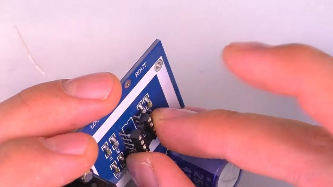
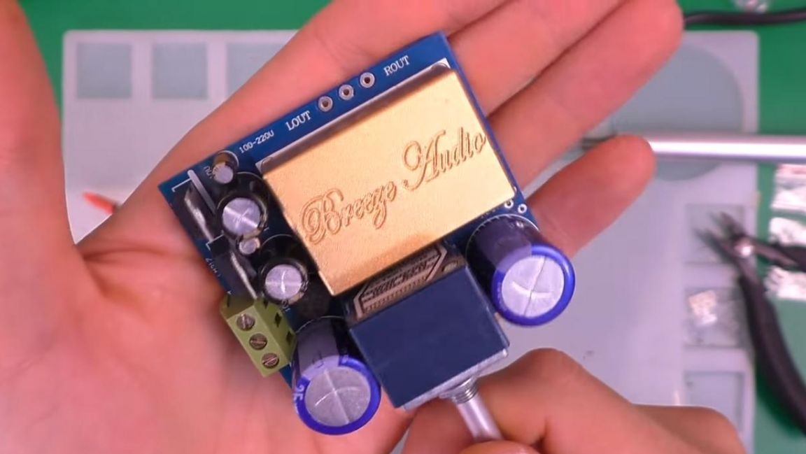
We insert the microcircuit into the socket, being guided by the key, after which we fasten the aluminum case to four screws for the hexagon.
Step Five
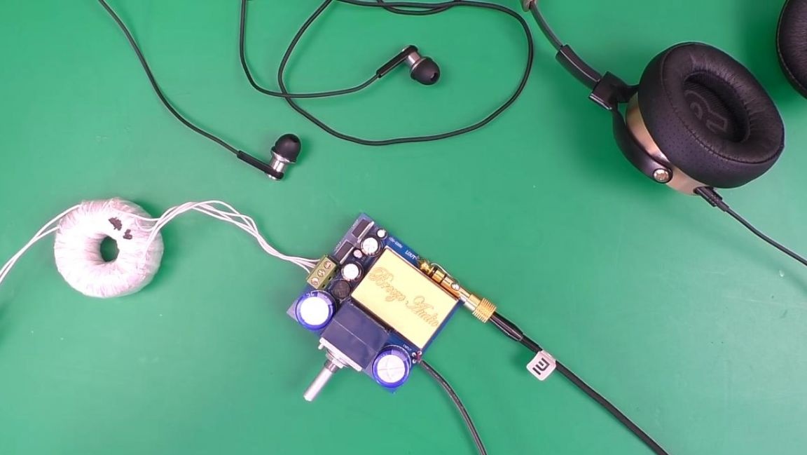
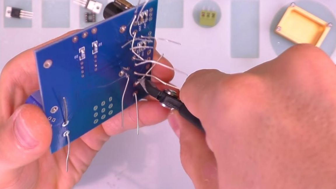
Since the potentiometer was not included in the kit, it will have to be purchased separately. We solder the potentiometer to the board and on this the preliminary amplifier is ready for testing.
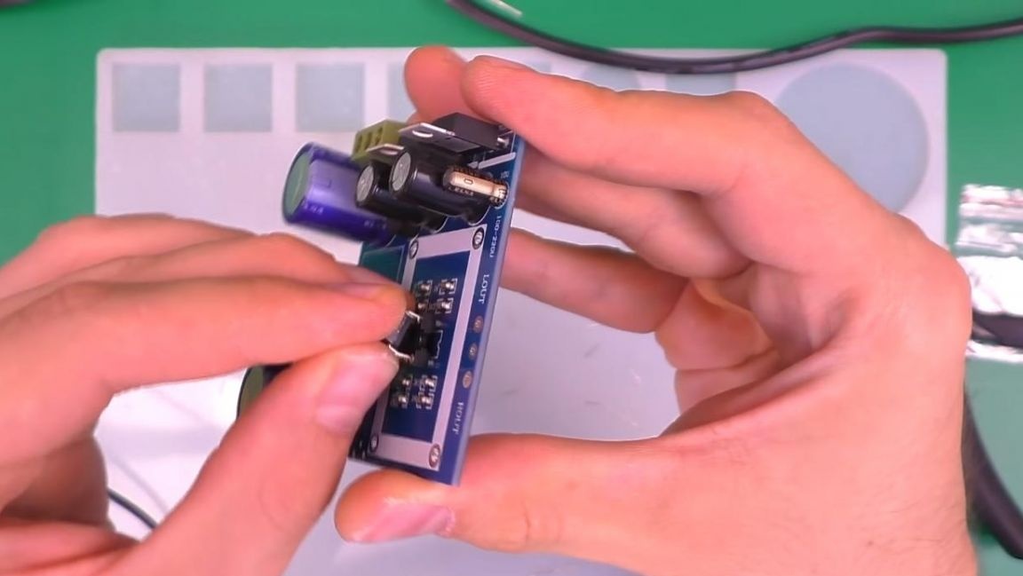
We solder the wires to the input and output, and also connect the power from a 12-volt power supply. We connect headphones or a sound amplifier to the output from the preamplifier and turn on the music on the phone or other playback device connected to the input.
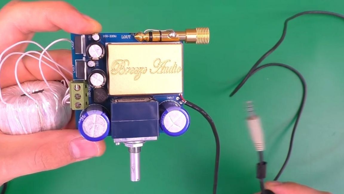
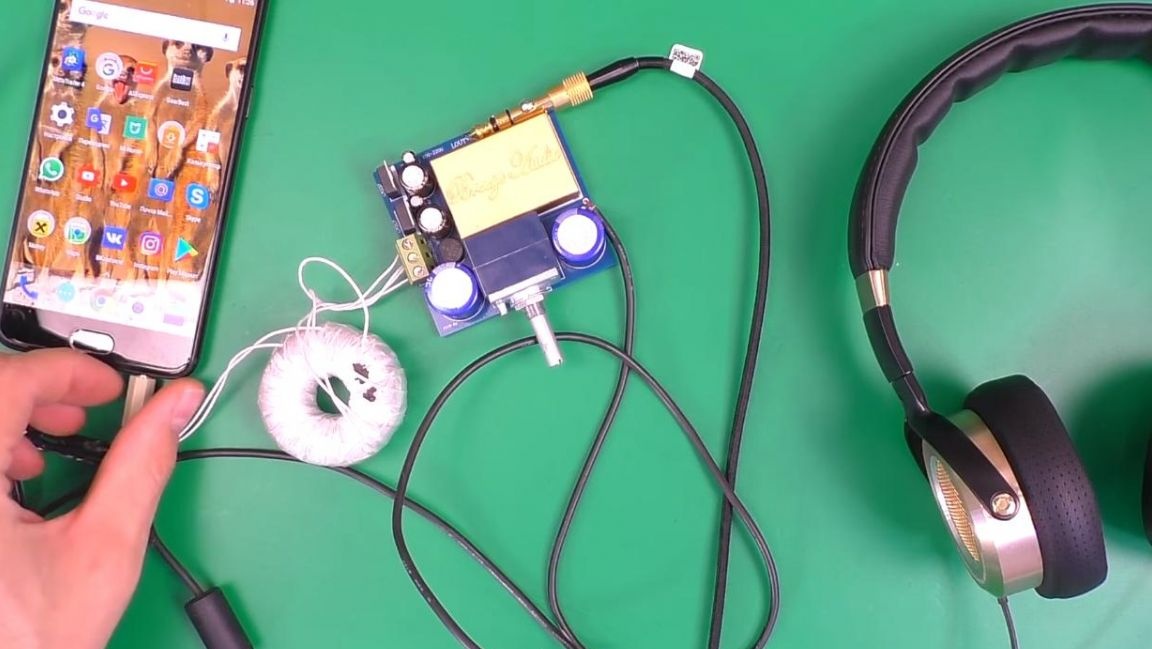
The pre-amplifier works great with headphones, the sound is transmitted clearly and without any audible distortion. This preamplifier will be needed for those who want to assemble an acoustic system with high-quality sound, as well as gain experience with the assembly of radio designers, which is useful for beginner radio amateurs.
That's all for me, thank you all for your attention and creative success.