
Hello to all lovers homemade. In this article I will tell you how to make a machine on a remote control do it yourself, in the assembly of which the kit kit will help, a link to it will be at the end of the article. This radio designer will help you learn how to use a soldering iron, it is especially useful for beginner radio amateurs, and it will also be a great toy for a child.
Before reading the article, I suggest watching a video with a detailed assembly of the kit and its verification.
In order to make a machine on a remote control with your own hands, you will need:
* Kit
* Soldering iron, flux, solder
* Finger batteries
* Multimeter
* Side cutters
* Device for soldering "third hand"
* Silicone soldering mat
* Double-sided tape
Step one.
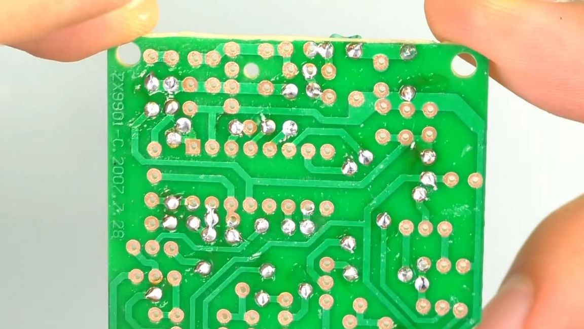
In the kit kit we are met by a single-sided printed circuit board with marking.
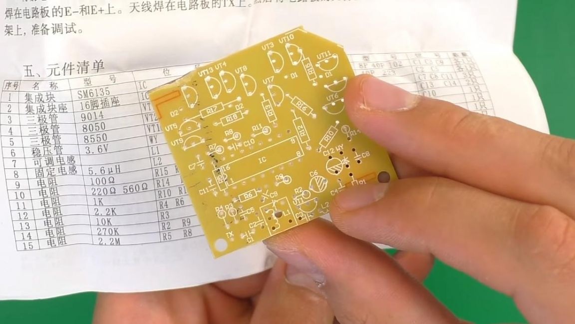
Also, for convenience, the instruction set with the circuit and all the ratings of the radio components indicated on it were put in the kit.
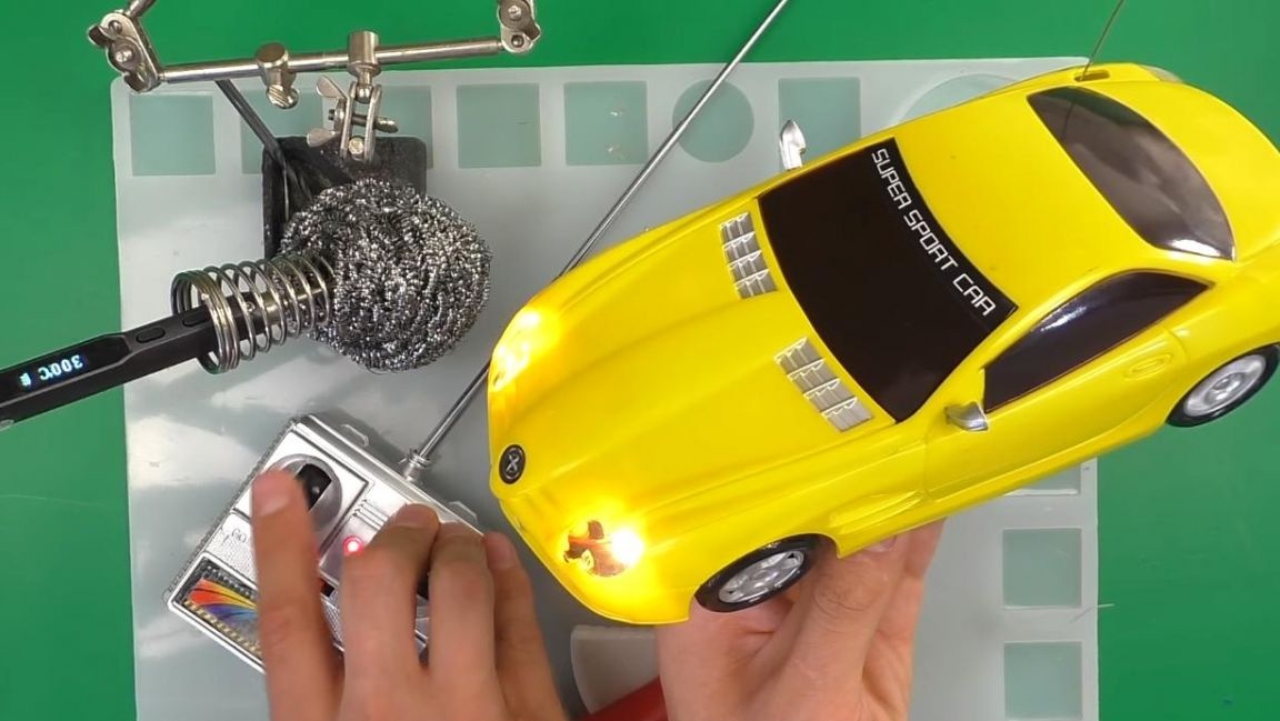
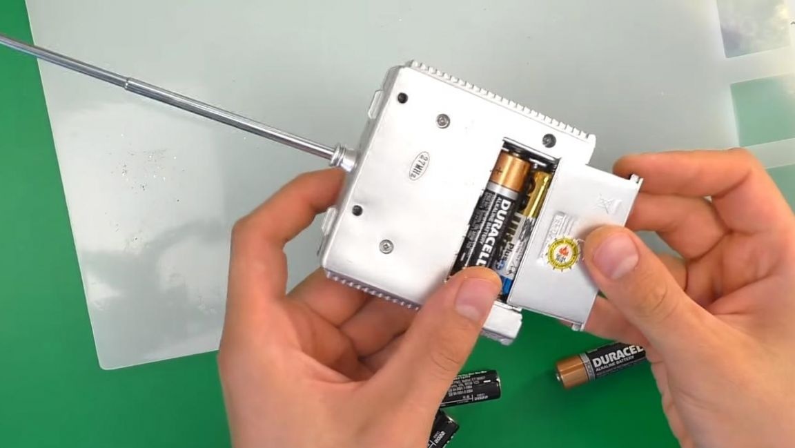
The control panel is already assembled into a single unit, so the entire assembly will only be associated with the installation of components on the board and the further connection of the drive and steering motors.
Step Two
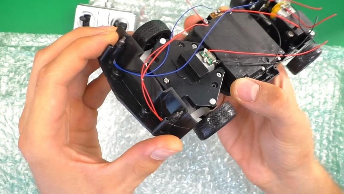
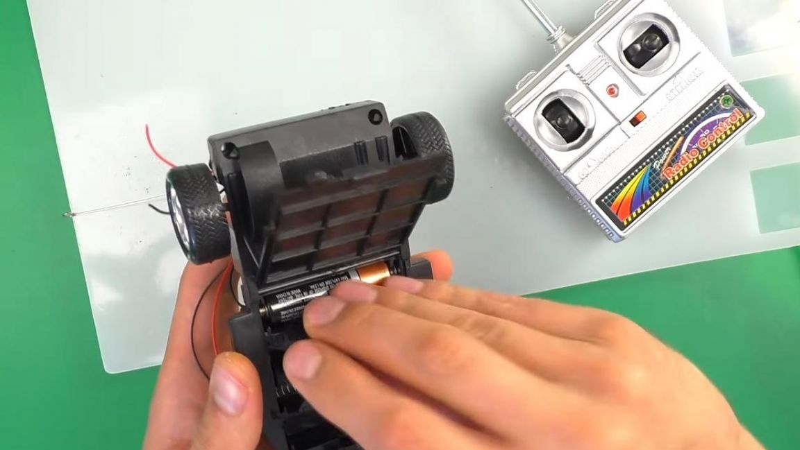
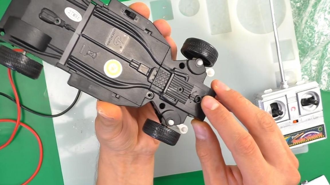
We proceed to disassemble the machine’s body, unscrew the kit with a screwdriver and see the wires coming from the headlight bulbs, as well as the electric motors, they are already soldered in advance, which is very convenient, since it does not require additional time for soldering.
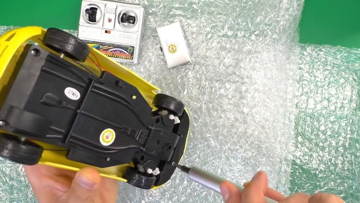
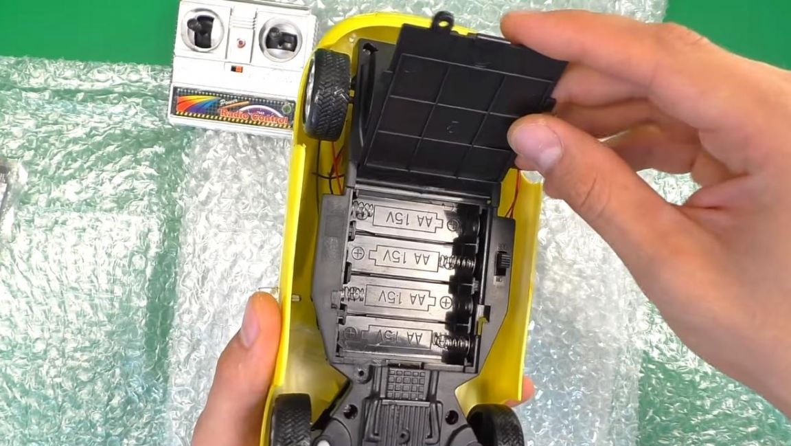
At the bottom of the machine there is a compartment for four finger batteries, in the future it can be transferred to the battery for longer operation and the possibility of charging.
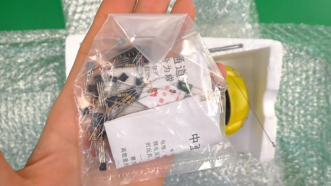
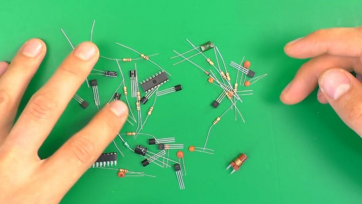
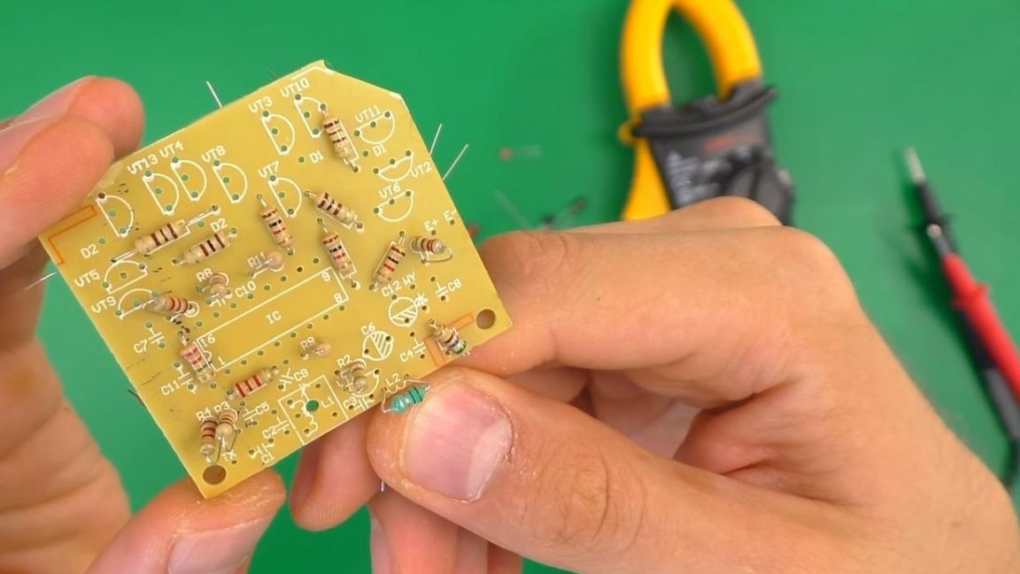
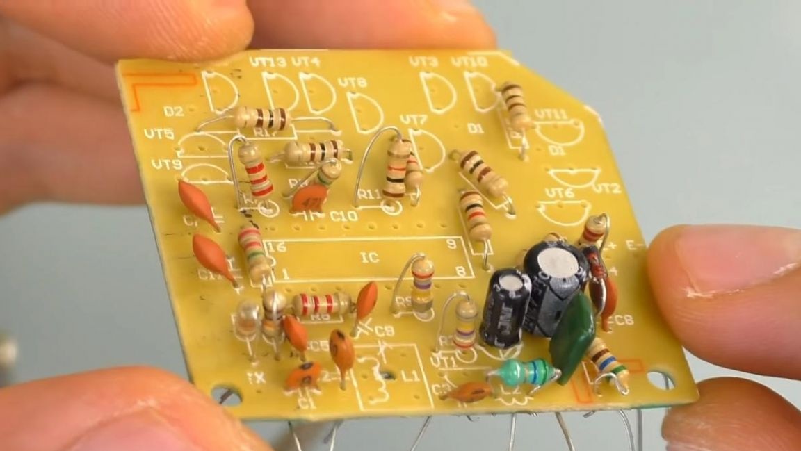
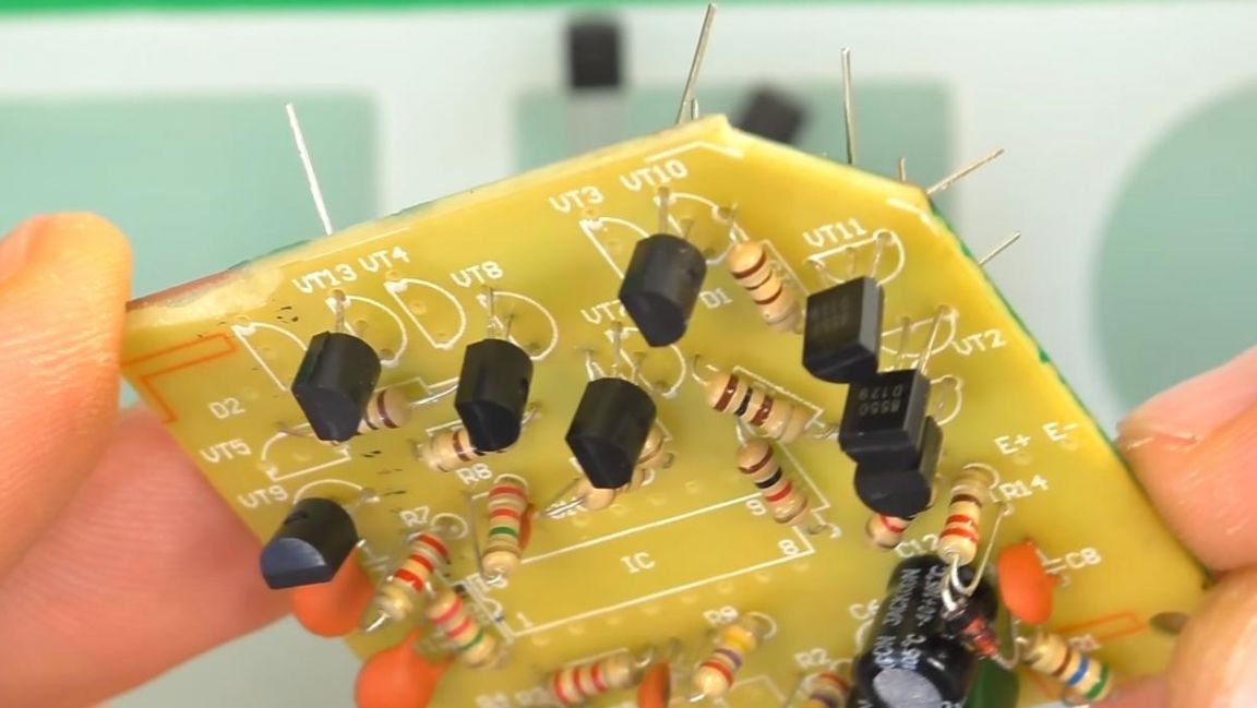
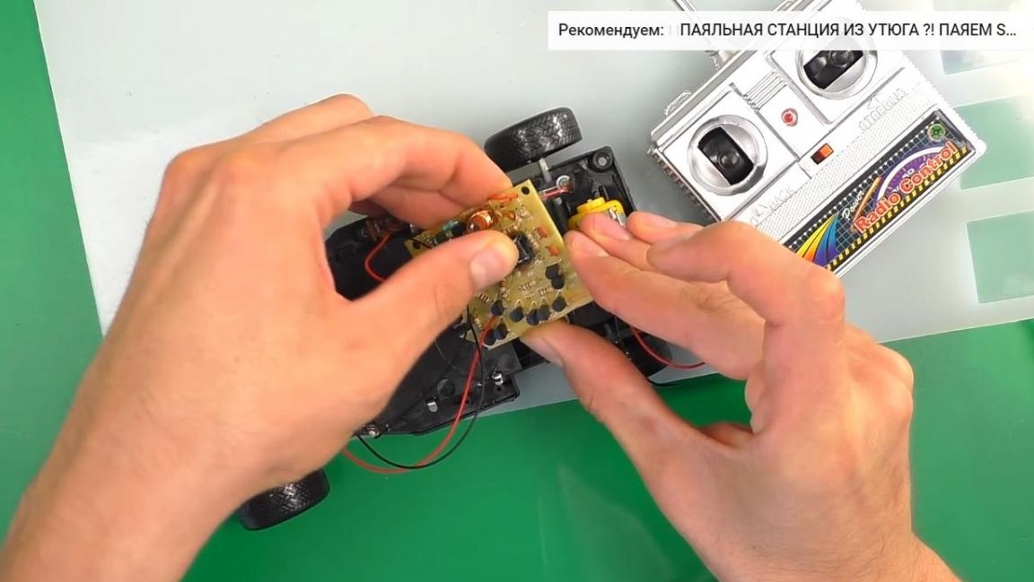
Now we will install all the components in their places on the board, there are a lot of them, most of them transistors and resistors.
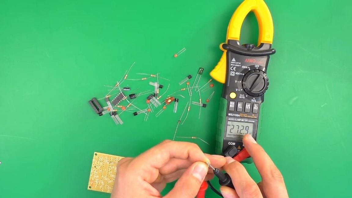
We determine the resistance of the resistors before installing them on the board, then insert them into their places according to the marking. You can determine the resistance in several ways, using a multimeter, color coding and a look-up table, as well as an online calculator.
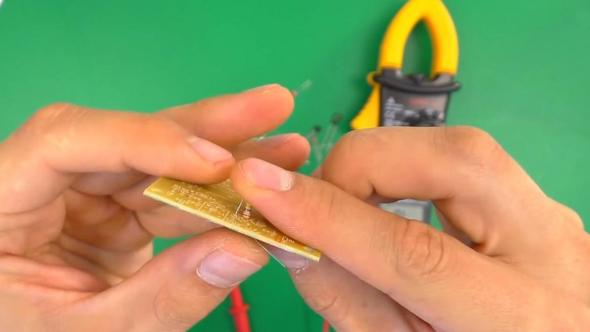
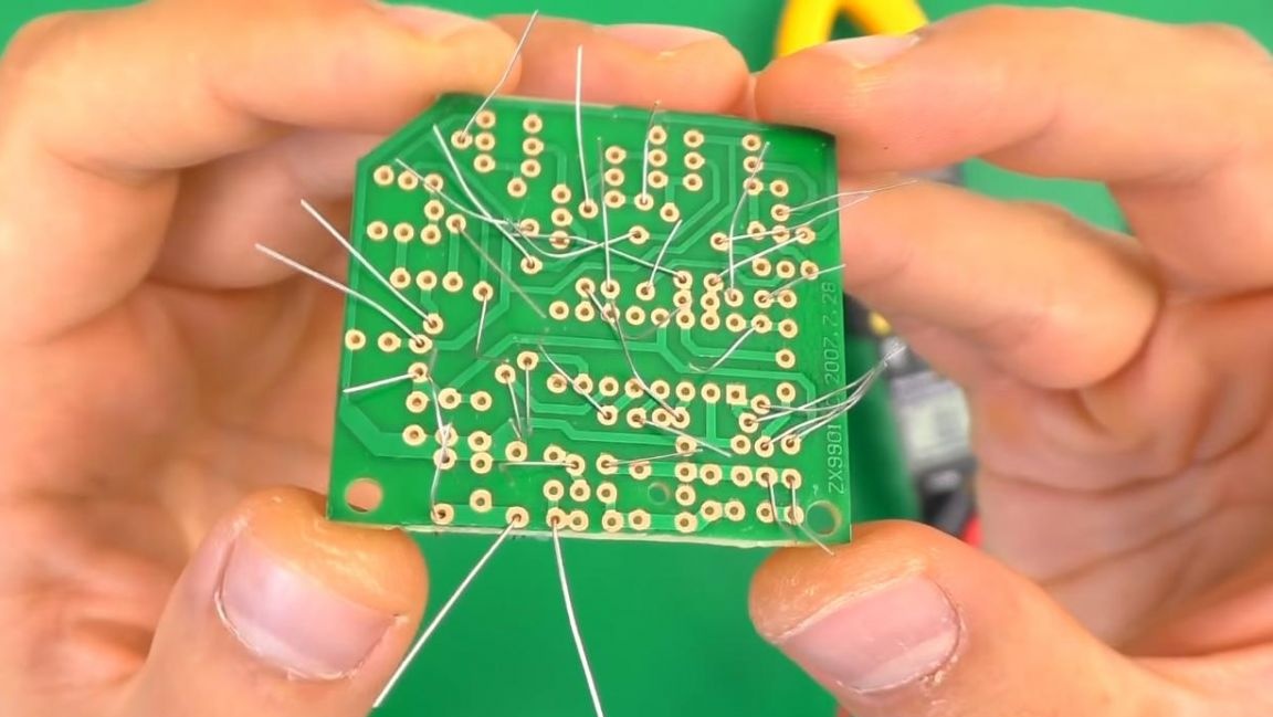
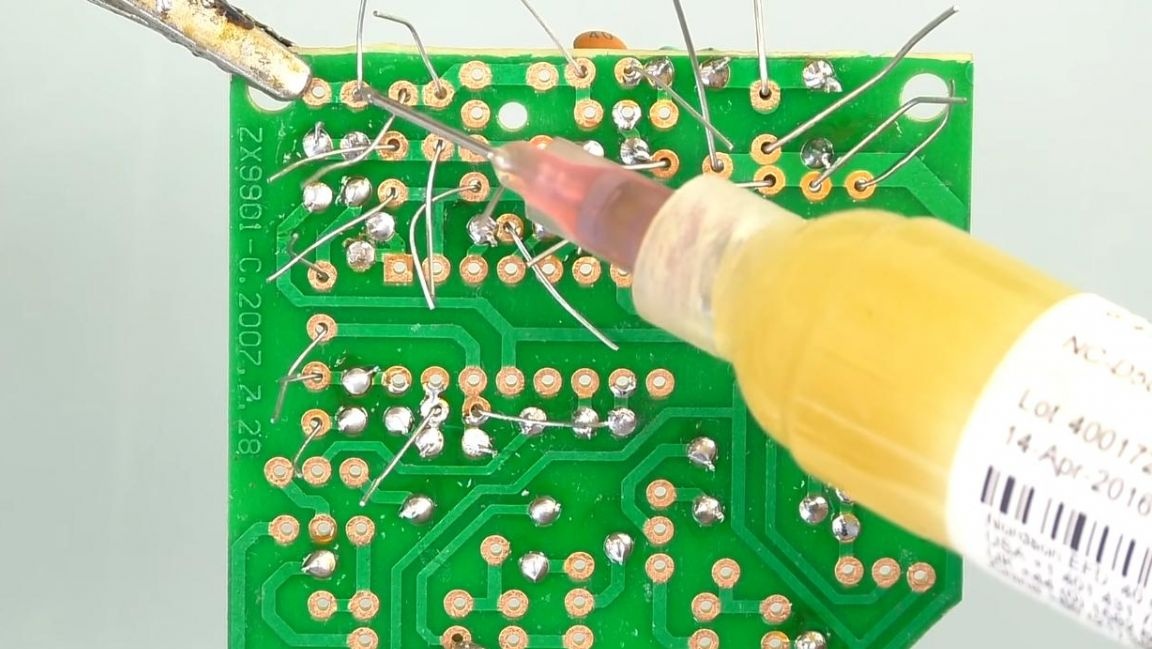
After the resistors, we set the inductance. On the reverse side of the board, we bend the leads so that the parts do not fall out when soldering.
Step Three
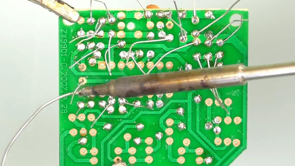
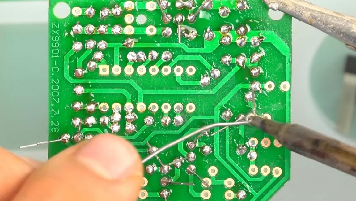
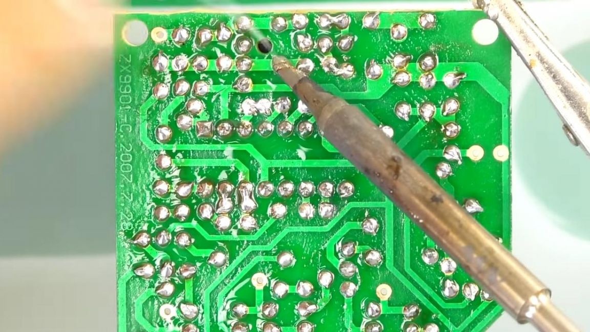
We fix the board in the "third hand" device and apply the flux to the contacts, after which we solder them with a soldering iron and solder.
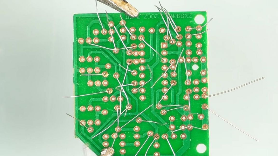

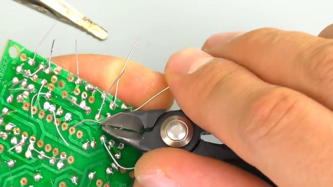
We remove the remains of the conclusions with side cutters. When removing pins using side cutters, be careful, as the board tracks can be accidentally torn out.
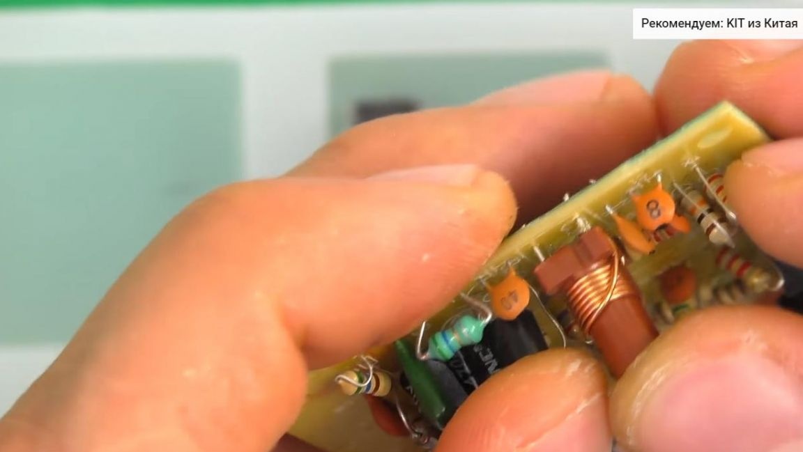
Then, we install a non-polar green ceramic capacitor on the board, after which we insert the polar electrolytic capacitors according to the rating, as well as the polarity. The long leg is a plus, a short minus, also the negative contact on the board is indicated by a shaded semicircle.
We apply flux to the contacts and solder the radio components, we also remove the remnants of the leads with side cutters.
Step Four
Now it's time to put the transistors in place.
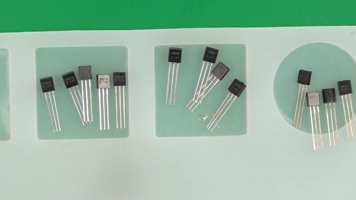
There are a sufficient number of them on the board, the main thing here is not to be mistaken, since they have different markings and differ from each other. For convenience, it is better to install first transistors of the same marking, and then others, when installing, we orient ourselves on the case and the image on the board of the same shape.
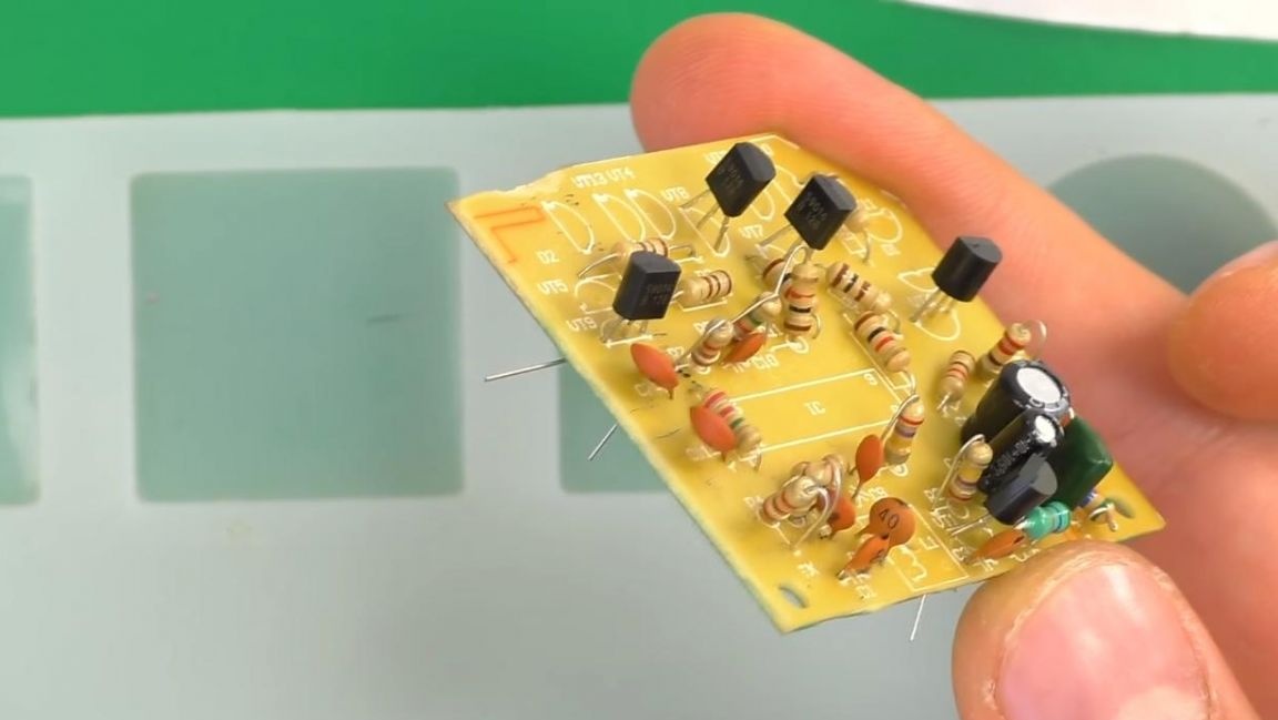
After installing the transistors, we bend their legs and solder them with a soldering iron and solder.
Step Five
We install the remaining parts on the board, namely the inductance coil and the socket for installing the microcircuit.
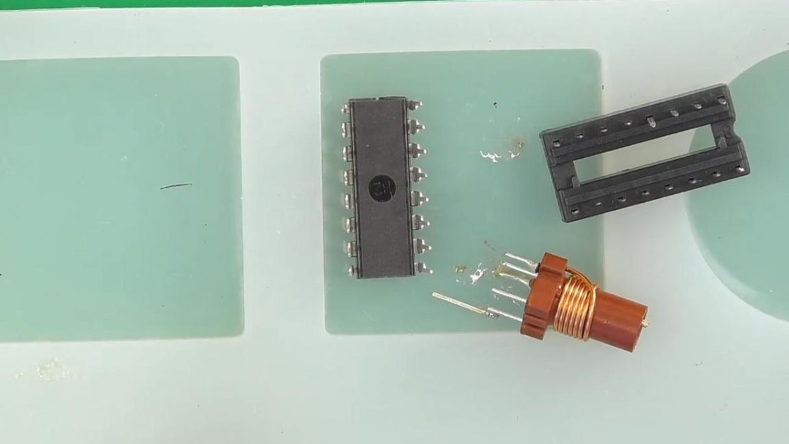
The inductance coil has three terminals on the one hand and two terminals on the other, so it cannot be installed incorrectly.
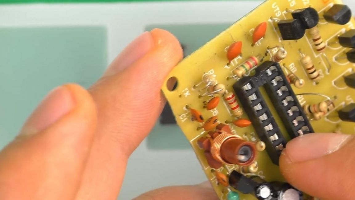
Next, we put the socket in its place, focusing on the key in the form of a recess on the case and marking the board.
Then we also solder them, as well as previous radio components.
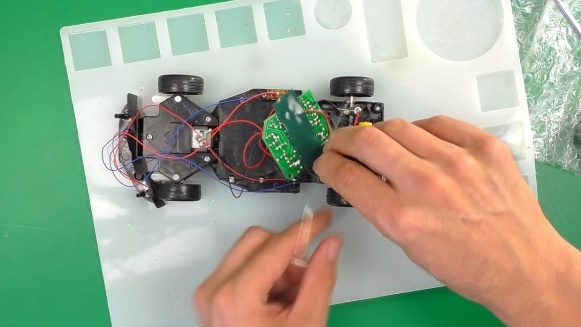
Then we install the board on the machine, solder the wires from the electric motors of the drive and steering, as well as the bulbs installed in the headlights.
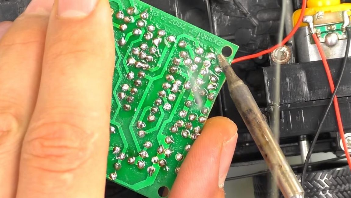
The correct connection of wires can be determined empirically by installing finger batteries in the compartment of the machine and the remote control, after which by pressing one of the remote control handles, you also need to insert the microcircuit in the socket on the board, guided by the key on the case and the board.
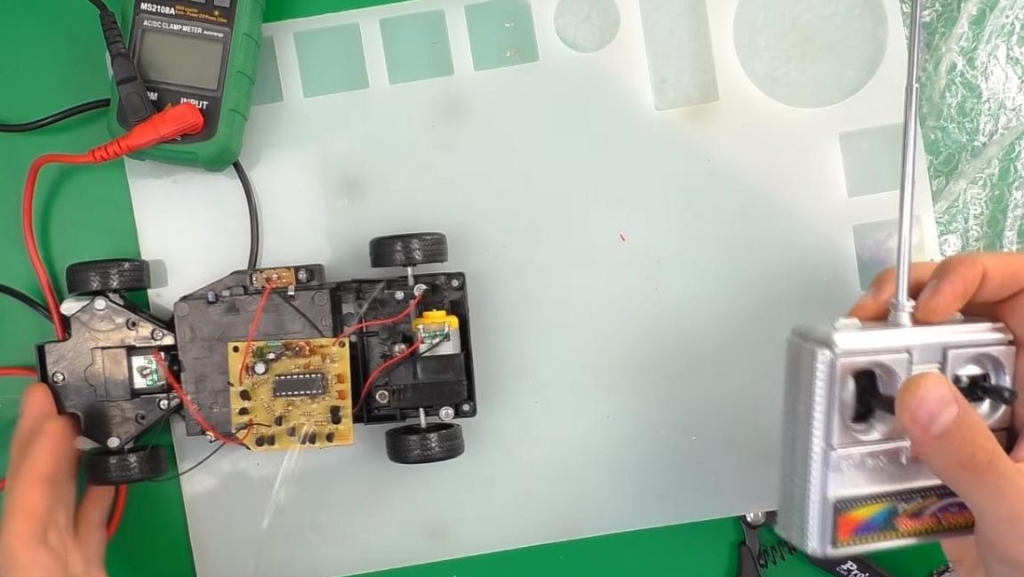
In order for the machine to go straight, there is a special regulator in the lower part.
For better communication and a larger range of the machine with the remote control, solder the wire to the antenna. The control board is installed on a double-sided tape to the body, after which we fasten the kit to the screws with a Phillips screwdriver.
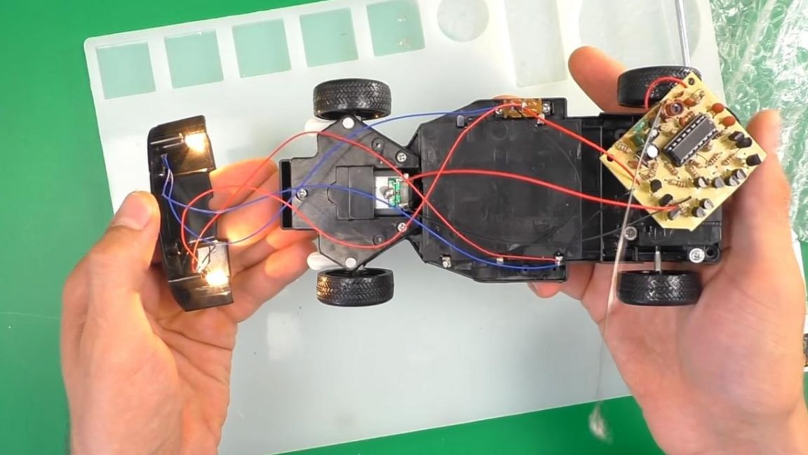
That's all for me, this remote control machine is completely ready.
Such a kit kit will appeal to those who want to assemble something from radio electronics for the first time with their own hands, as well as gain experience in this area. For children, such a toy in the form of a car will be excellent entertainment, and if necessary it can be supplemented with a battery, which in case of a discharge can be recharged and used again without spending money on buying new batteries.
Thank you all for your attention and creative success.