
Hello to all lovers homemade. In this article I will tell you how to make a player from a disk drive with a remote control do it yourself, in the assembly of which the kit kit will help, a link to it is at the end of the article. This kit kit will help you make a player from a regular disk drive, or in other words, a kind of radio on an optical disc with a remote control. Such a radio designer will also help in the development of the basics of radio electronics and will be useful for beginner radio amateurs.
Before you read the article, I suggest watching a video where the entire assembly process of this kit kit is shown, as well as its verification in operation.
In order to make a player from a disk drive with a remote control do-it-yourself, you will need:
* Soldering iron, flux, solder
* Kit
* Device for soldering "third hand"
* Optical drive
* Computer power supply
* Side cutters
* Silicone soldering mat
* Phillips screwdriver
Step one.
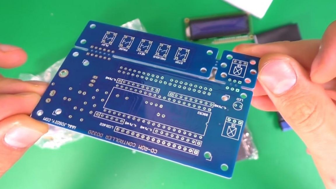
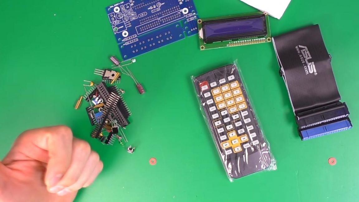
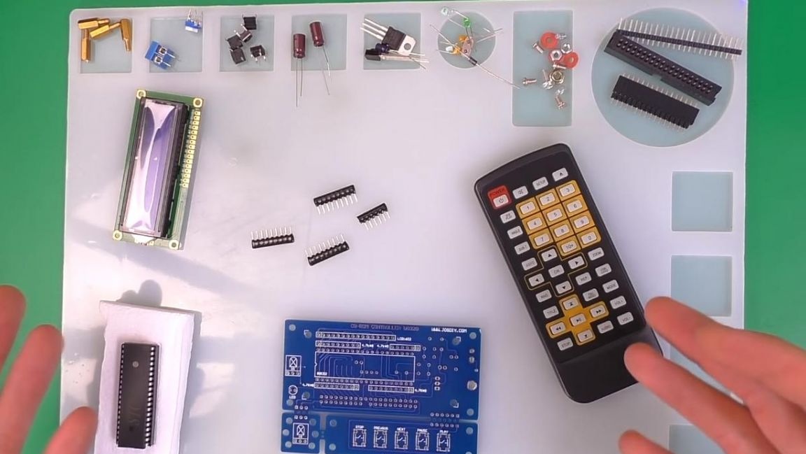
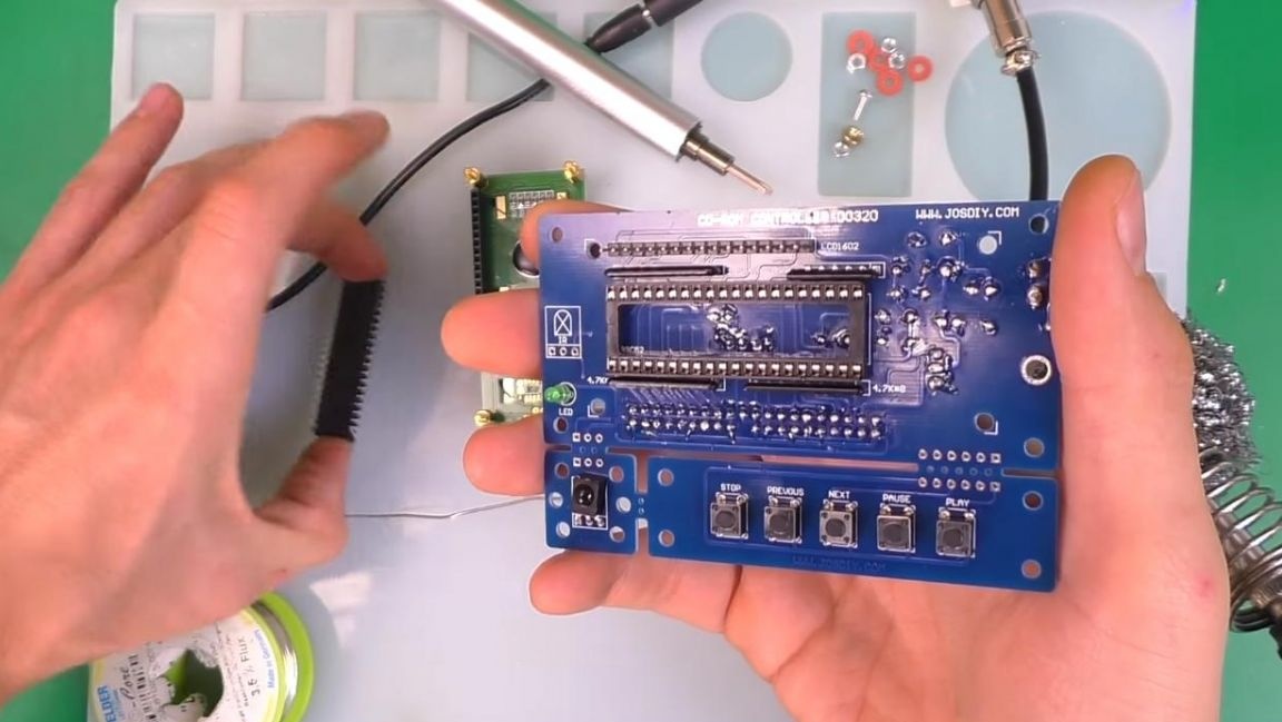
To begin, consider what comes with the kit. There is a double-sided printed circuit board with metallized holes, its workmanship is at a good level.
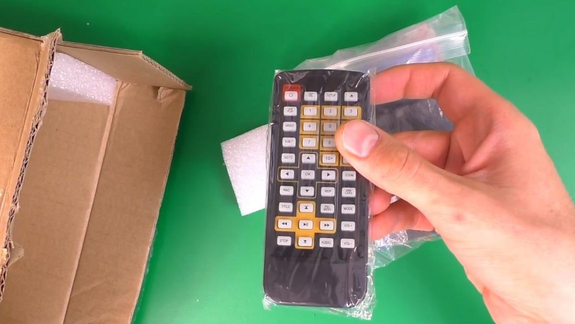
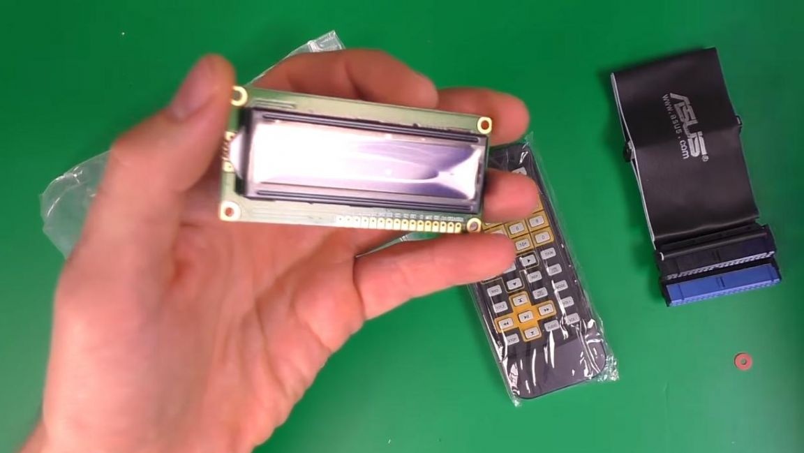
A remote control is provided for controlling the drive, which will simplify the process of switching songs and other actions with the player.
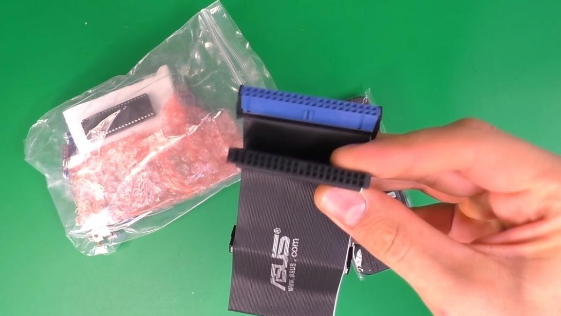
Also included is an IDE cable for connecting a disk drive, it is a fairly old interface and is no longer used in new computers.
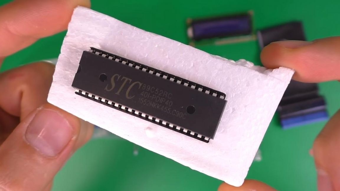
To display information, for example, the duration of a song and its order, there is a display, and the main organ is the controller chip installed in a special socket.
In a separate bag, there are other parts, such as resistors, capacitors, and so on.
Step Two
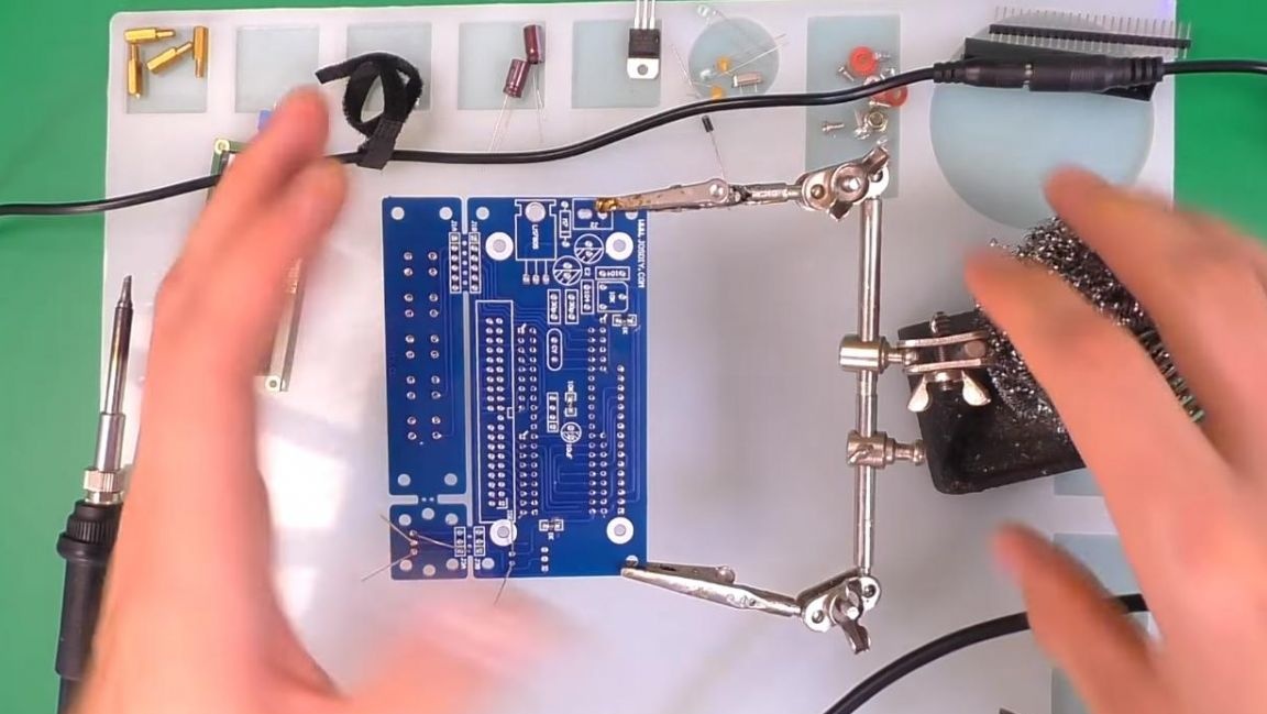
We proceed to the assembly of the radio constructor. We place all the components on a silicone soldering mat, so the parts will not be lost and will always be in one place.
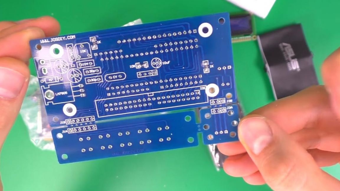
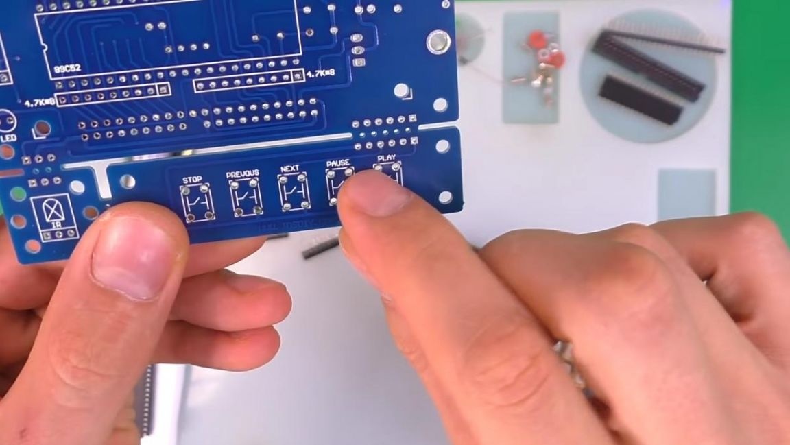
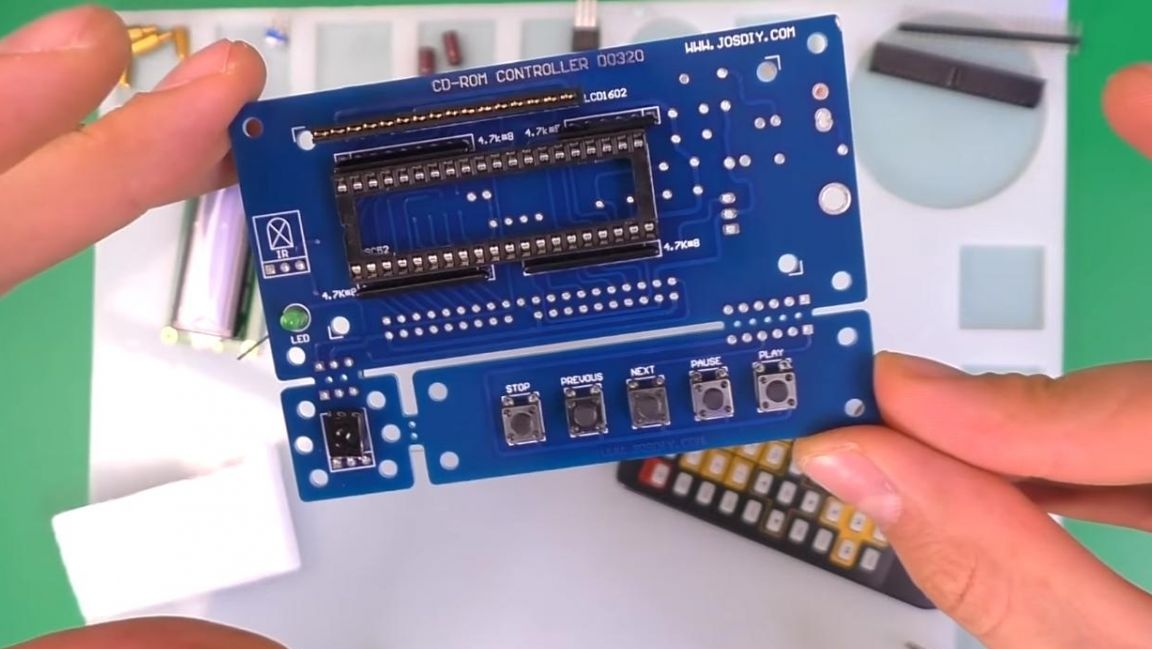
The board itself consists of three parts, fastened together, on one there are all the main parts, on the other element for control using the remote control, and on the third there are control buttons. If necessary, these parts of the board can be disconnected and install all the elements in the right place, for example, on the front panel.
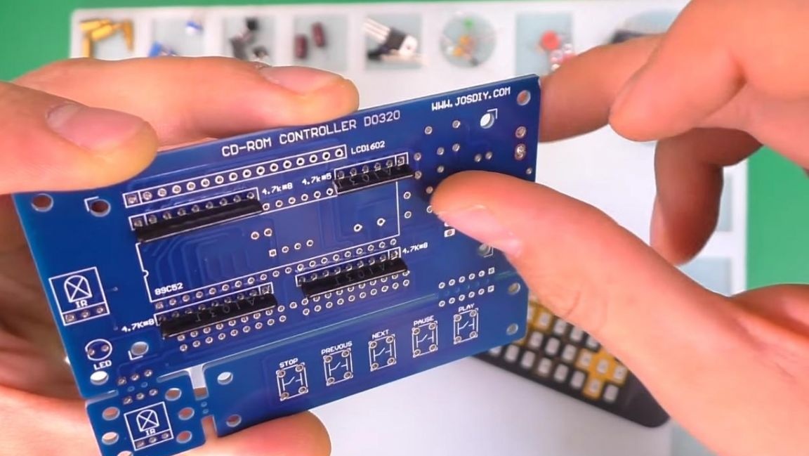
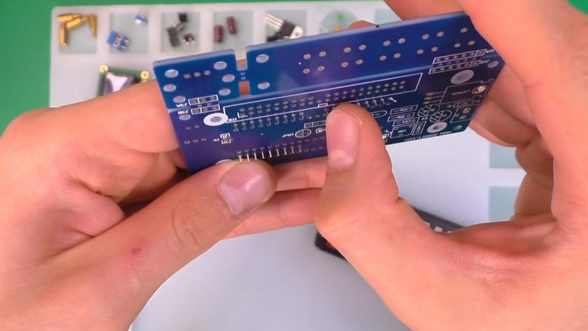
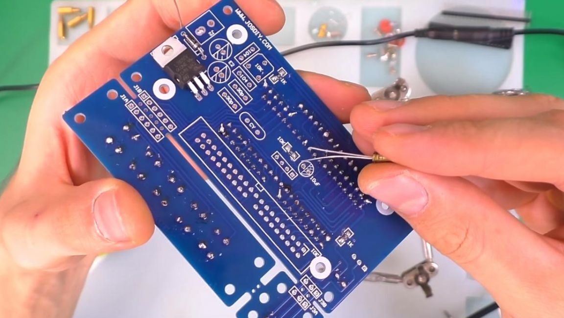
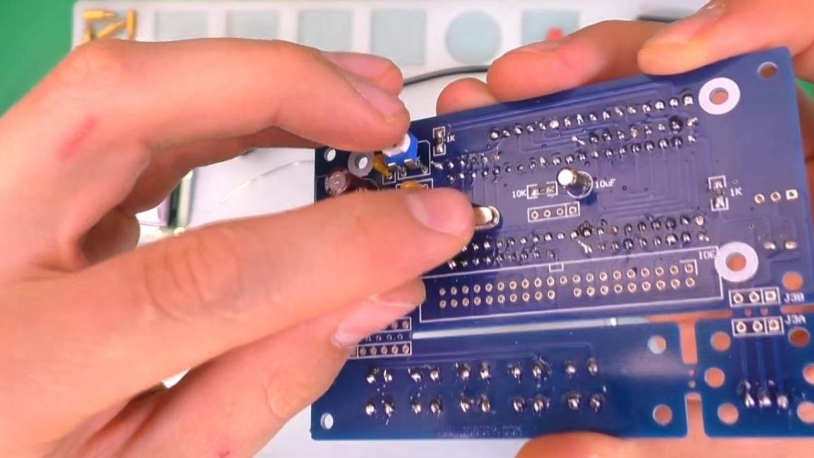
We begin the installation of the board by installing the resistor assemblies, they are marked, as well as on the board itself, plus the fact that you do not need to determine the resistance, which means that you do not need a multimeter here, when installing, we observe the position of the points on the case and the board.
In order to prevent the parts from falling out when soldering, we bend the extreme leads on the back of the board.
Step Three
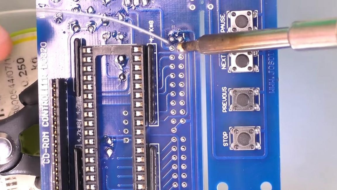
Next, we install the control buttons in their place, as well as the infrared receiver.
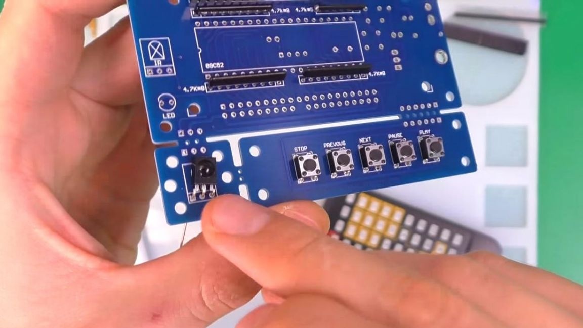
To indicate operation on the board, an LED is provided, we insert it according to the polarity, the long leg is plus, short-minus, also on the LED there is a bevel that needs to be combined with the image on the board.
Then we insert the socket for installing the microcircuit, for this we take out the microcontroller and combine the keys on the case and the board marking, on the reverse side we also align the conclusions.
Step Four
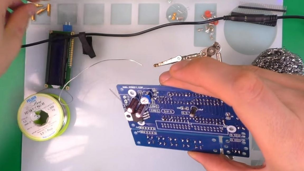
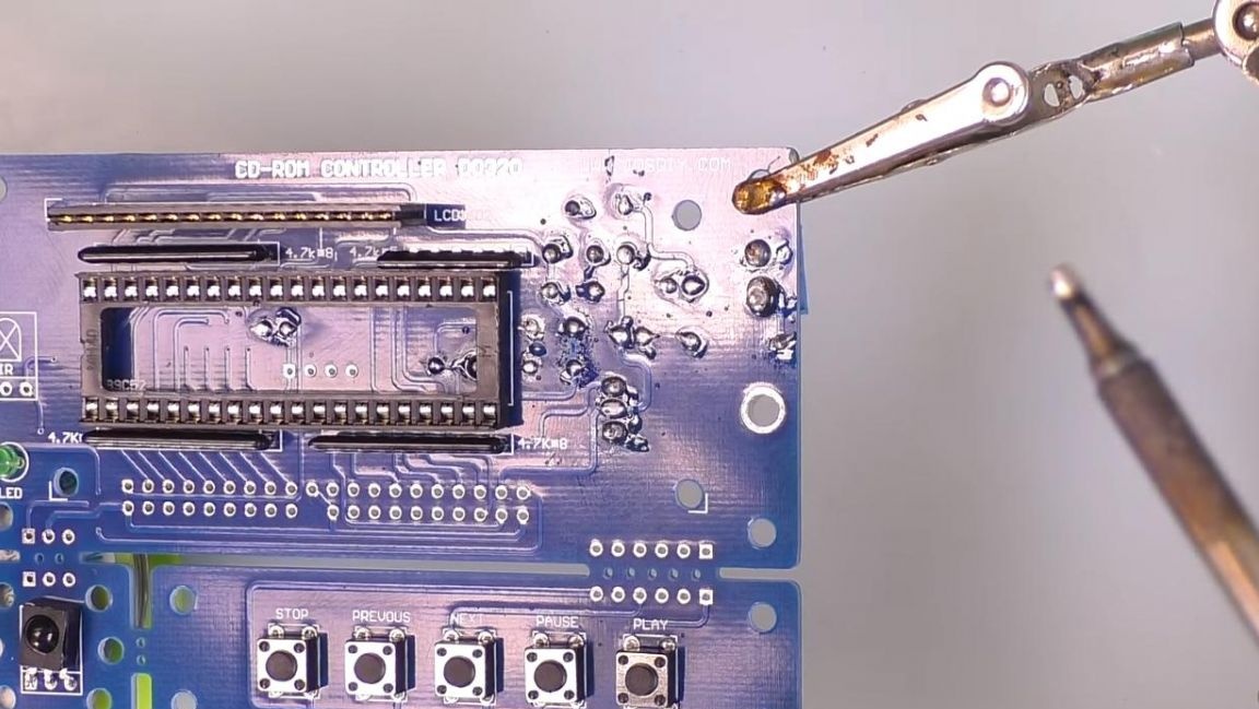
We clamp the board in the "third hand" soldering device and solder the conclusions to the contacts using a soldering iron and solder with the flux already inside.
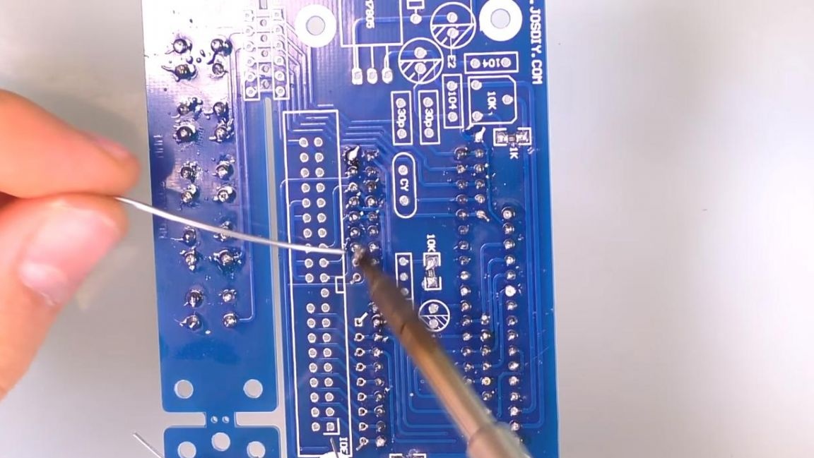
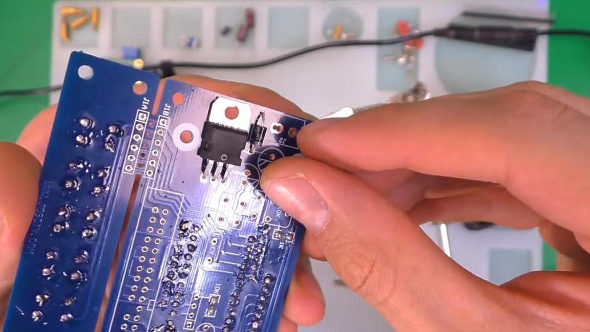
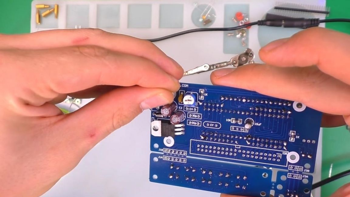
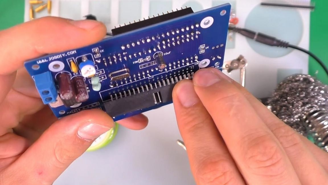
As you can see from the back, the SMD resistors have already been installed in advance, which also facilitates assembly. Next, we install a voltage stabilizer, guided by the pattern of the case on the board, bend it and press it, put a diode next to it combining the strips.
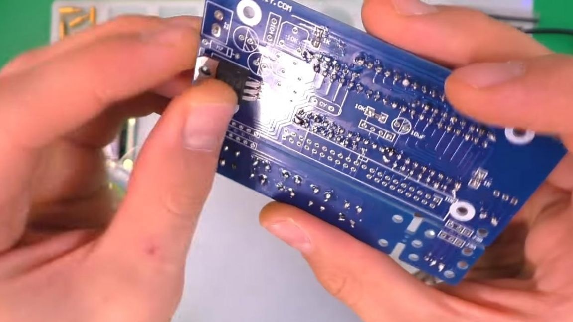
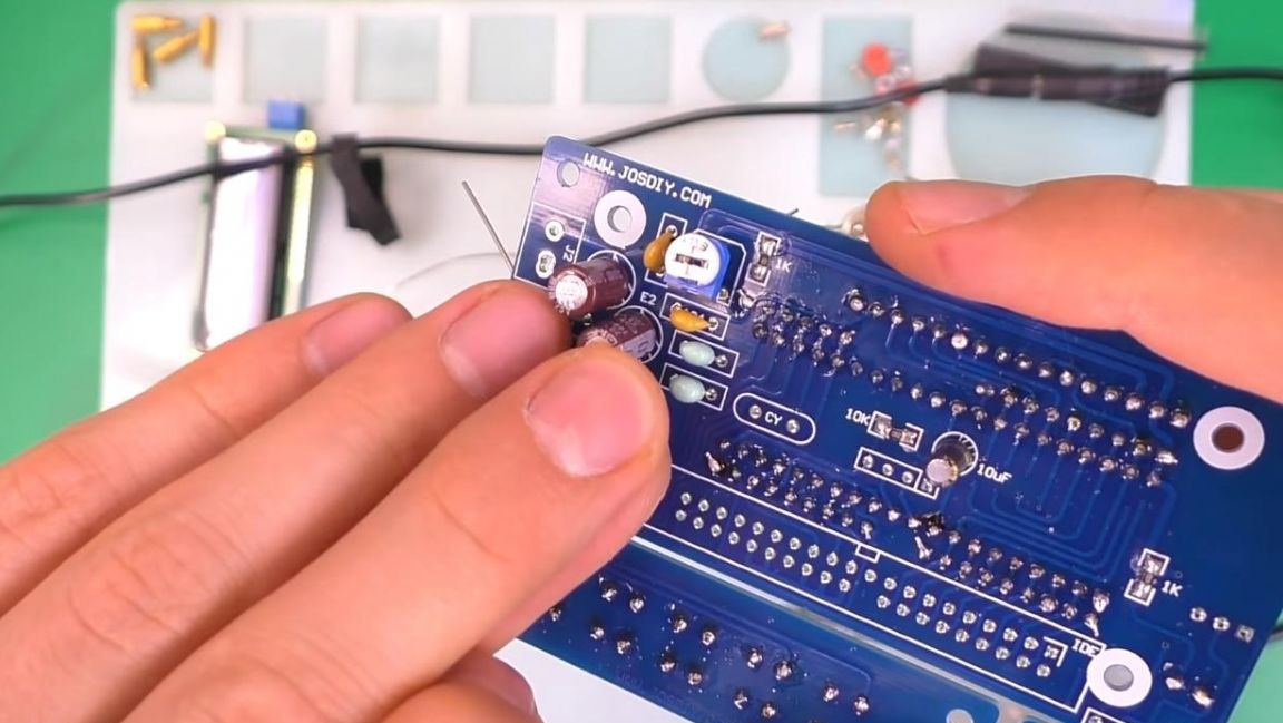
Then we insert the polar capacitors, while observing the polarity and ratings, the long leg is plus, short minus, on the board the minus is indicated by a shaded semicircle.
On the reverse side of the board, we pin the conclusions, they are just inside the socket.

To configure the display, we put a variable resistor on the board, then non-polar ceramic capacitors and quartz.
For convenience, it is better to remove the conclusions of the radio components before soldering, this can be done most easily using side cutters. When removing pins using side cutters, be careful as you can accidentally tear tracks out of the board. After that, we solder the conclusions to the contacts, fixing the board in the soldering device, for a better soldering, a little flux can be applied.
Step Five
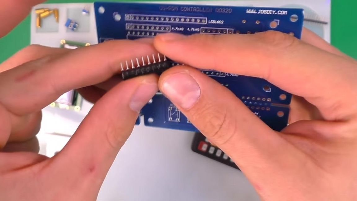
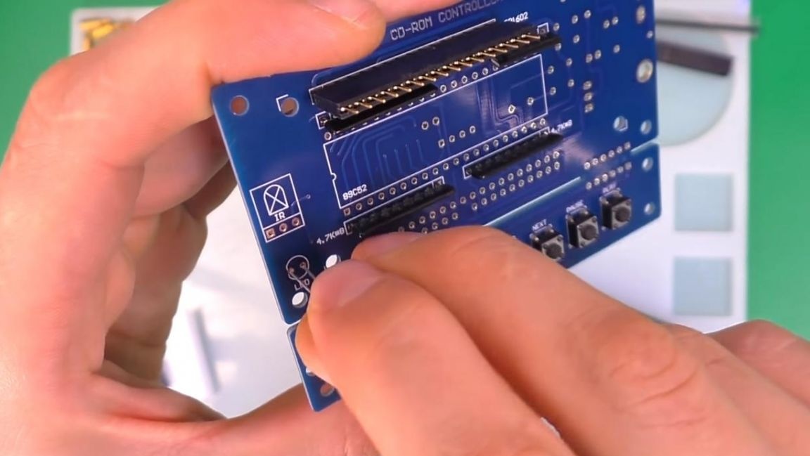
To connect a disk drive, install and solder the IDE connector on the board.
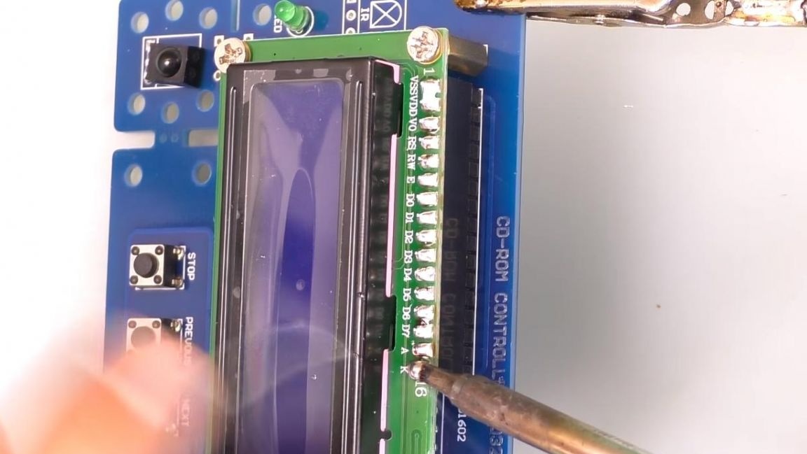
It remains to install the microcontroller and solder the display. The display is mounted on the board using spacers with internal and external threads, we fasten it to them with a Phillips screwdriver.
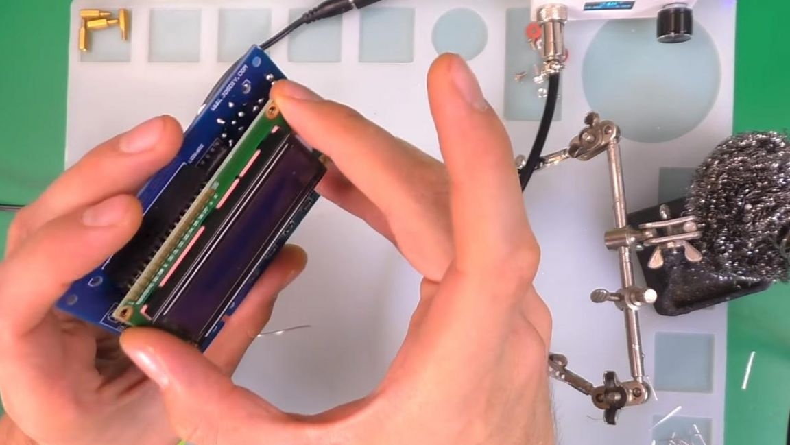
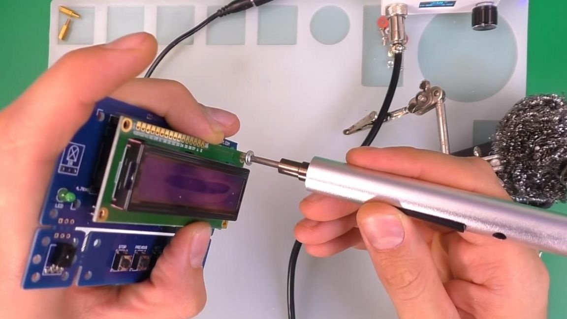
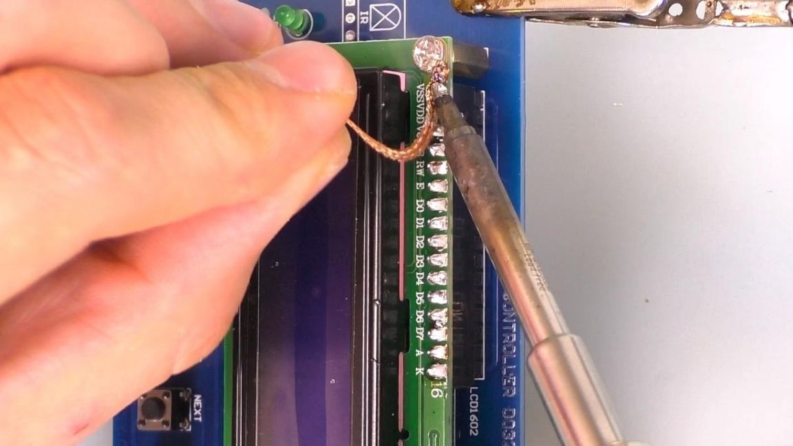
The nuts on the back side should not be screwed yet, first you need to solder the contacts to the display, and then remove it and install the microcontroller in the socket, while you need to combine the key in the form of a recess on the case and the socket itself. If the display contacts are soldered together, this can easily be fixed with a copper soldering screen that absorbs excess solder. It is not recommended to install the chip during soldering, as it may fail due to static electricity.
Step Six
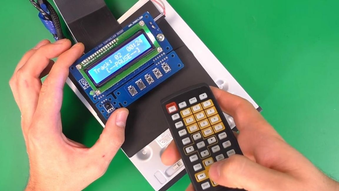
The board is fully assembled, which means that the time has come to check it. The board is powered by a voltage of 8-12 V, we connect the power wires and see that its consumption is less than 1A.
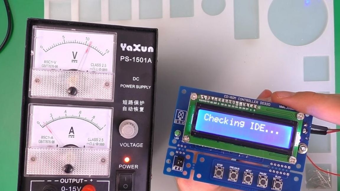
Adjust the brightness of the display using a variable resistor. We test the device on a DVD drive from a computer, connect it to the connector on the board via a cable.
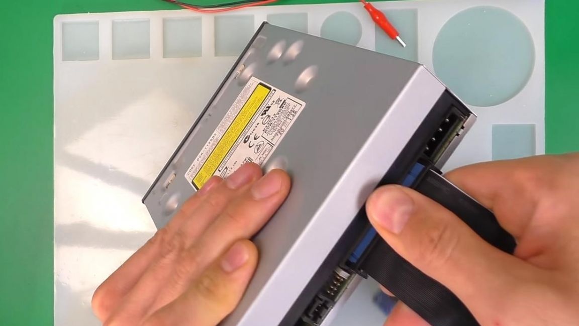
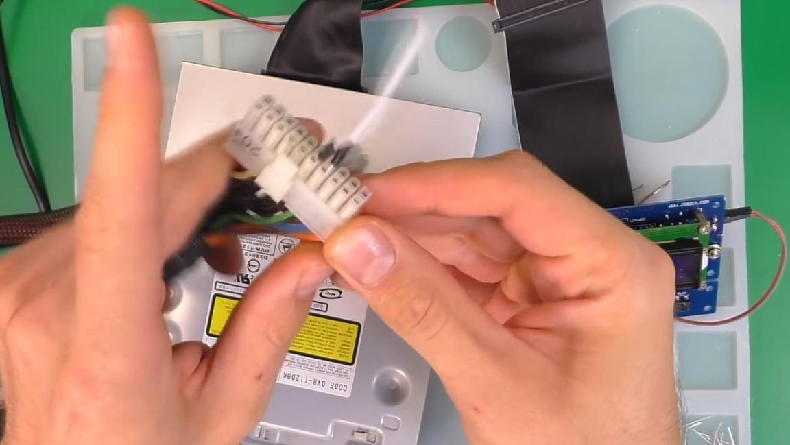
We supply power to the drive from the computer’s power supply, and so that it starts we close the green and black wires, the device itself is also powered from the unit, the yellow wire is +12 V, the black wire is.
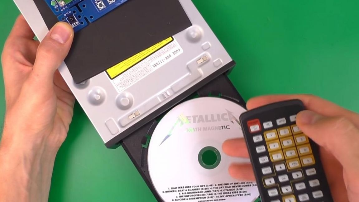
We turn on the power supply and see that the inscription CD-ROM PLAYER appears on the display, then the music on the disc starts playing, you can switch it both from the buttons on the board and on the remote control.
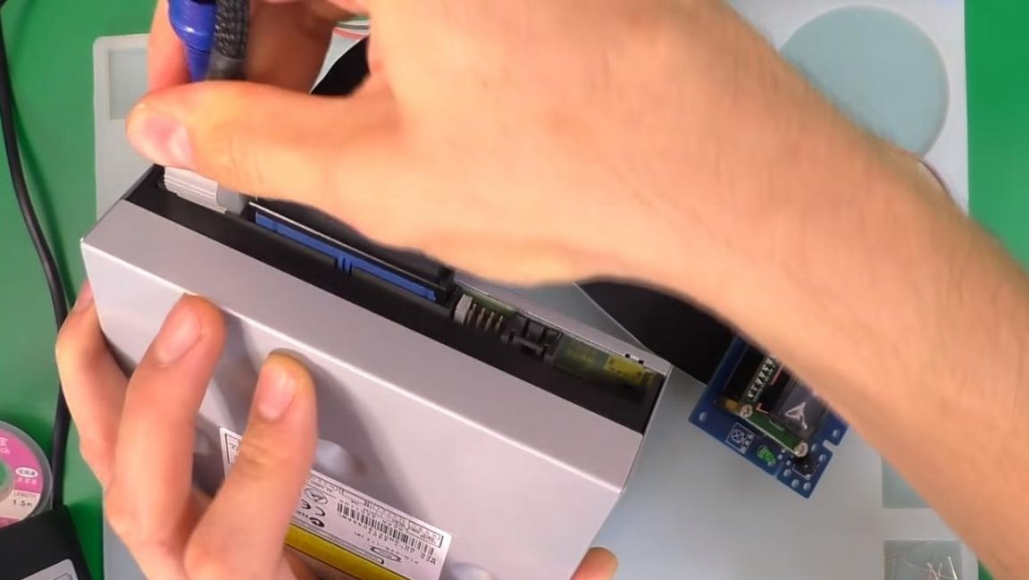
The sound output is removed from the contacts located on the side of the drive loop, the middle contact is the common output, and the two contacts at the edges are the left and right signals. You can also eject a disc using the remote control.
That's all for me, this kit kit is useful for those who want to try their hand at radio electronics, as well as those who want to assemble a player on their own optical discs.
Thank you all for your attention and creative success.