
It’s getting a little hot, summer and all that. I have a Chinese fan on my desk, but I work at different ends of my new large desk, and the fan almost always blows by, and turning it around every time is somehow sad. So today we will do a fan with automatic aiming at the target.
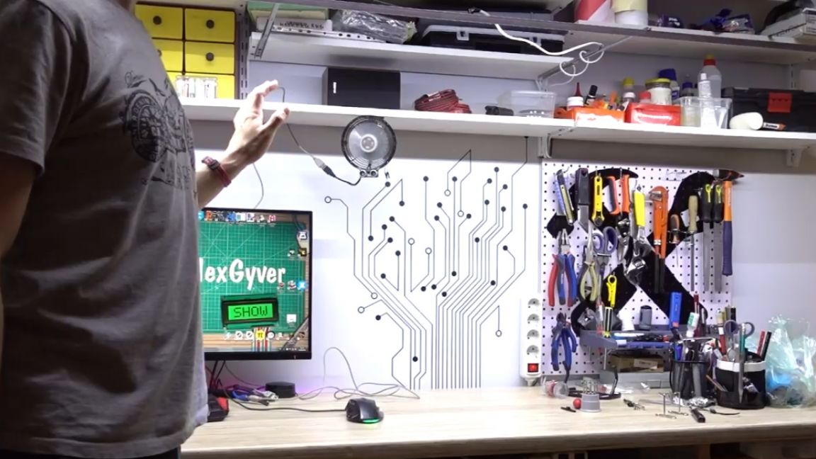
So, we need to track the position of the target, taking into account the situation on the table, so that the fan does not aim at other objects. Ideally, of course, you could take a raspberry pi minicomputer with a camera, and use a machine vision library to recognize movements or a bright T-shirt.
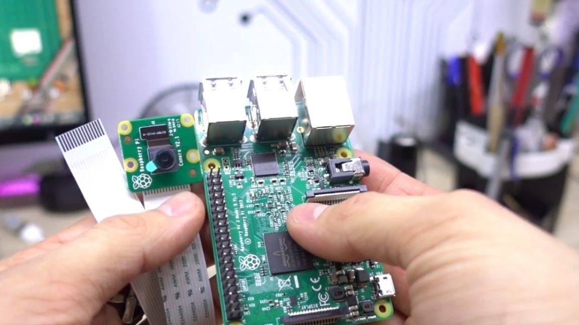
But this is a rather difficult task, and the board itself costs more than 10 times more expensive than the platform arduino, which can not cope with the camera. But besides the camera, there are other ways to determine the target, for example, a penny ultrasonic distance sensor.
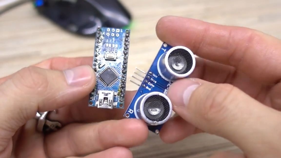
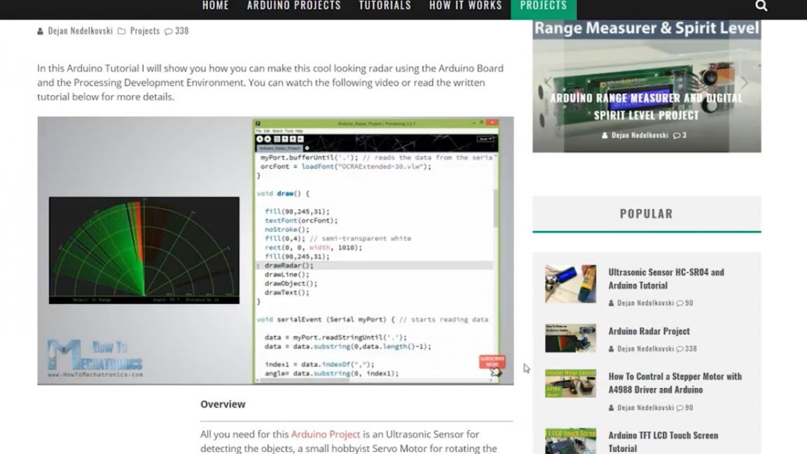
Once I came across on the Internet an interesting project "radar" based on arduino and this sensor. The project itself is pretty useless, but the idea itself is wonderful - to rotate the distance sensor and scan the space, tied to the angle of rotation.
Let's repeat this project for fun, and then we will move on.
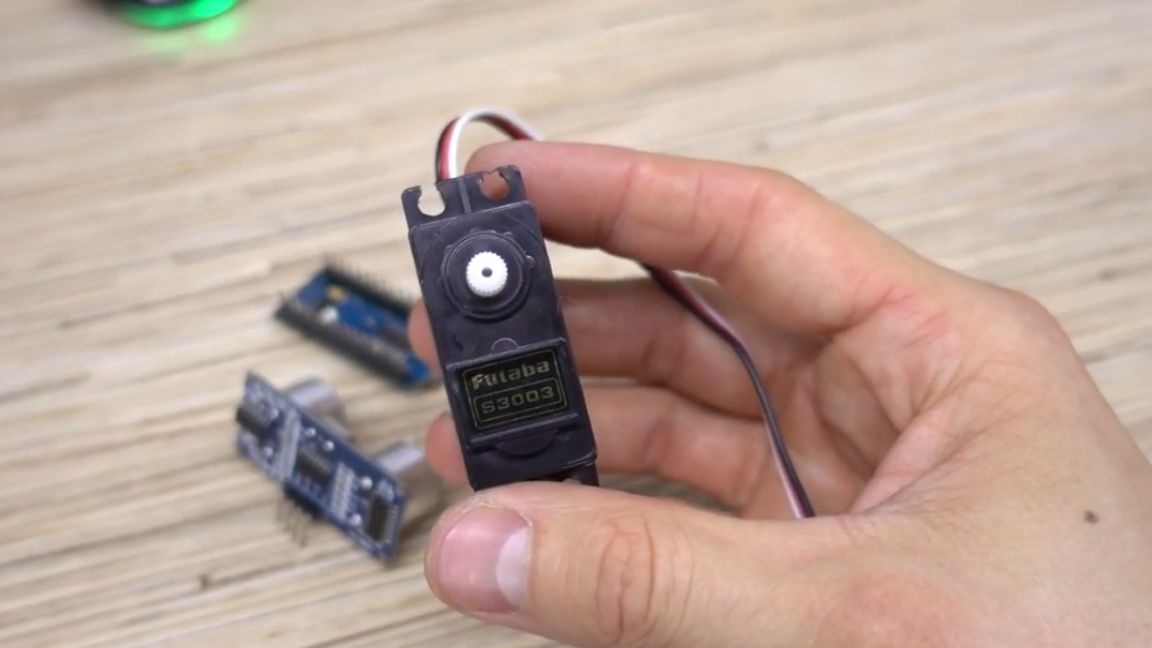
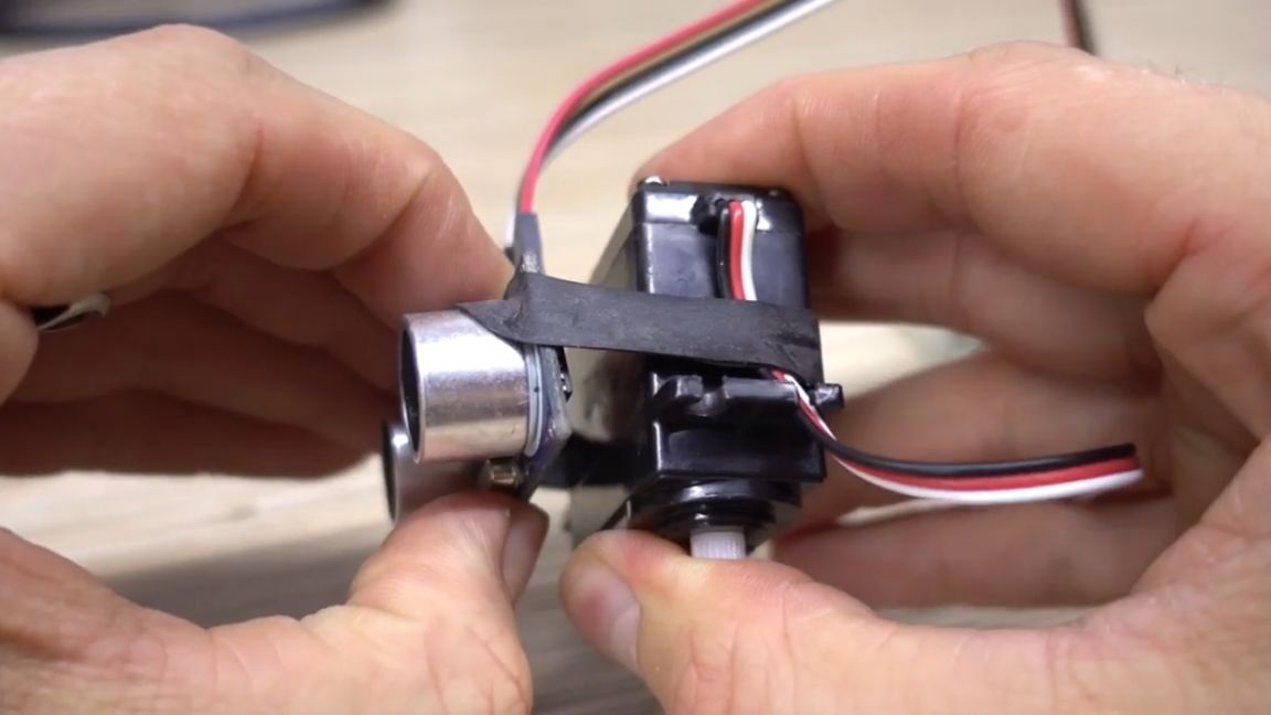
This means that the sensor must be rotated, for this, the usual model servo is used (who does not know, the servo is a motor with a gearbox and feedback to the angle, that is, we can set it the rotation angle, and it will turn on it).
Let's not be smart, and just fix the sensor using the ring from the bicycle chamber.
We assemble the circuit on a breadboard.
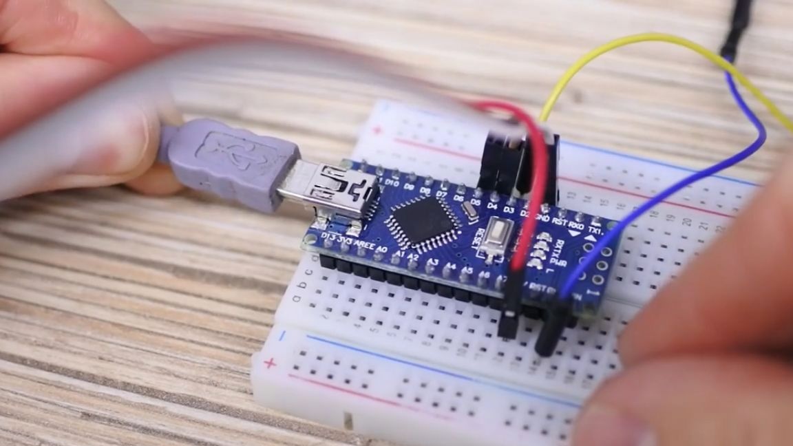
That's all, it remains to download the firmware in arduino. This version uses a faster library.
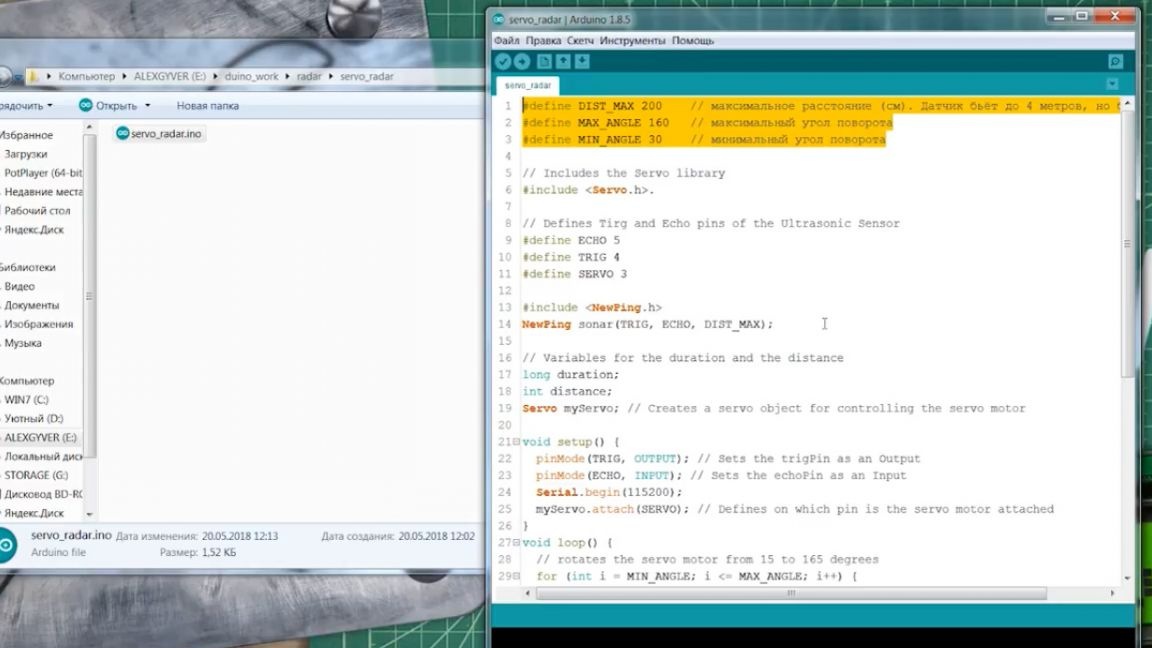
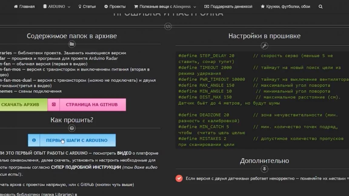
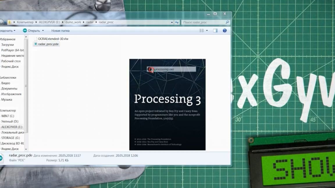
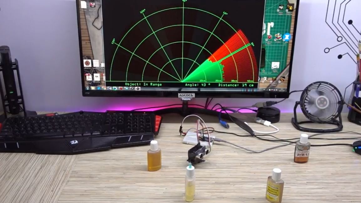
You can download the sources on the project page, the link can be found in the description under the video. There you will find all the detailed instructions, in particular a huge article for those who first picked up the arduino. In general, we load the firmware into the board and our radar comes to life. Now on the computer you need to run a program that will receive data from the radar (it is also in the project folder, but you need a processing environment to start it, you can download it on the official website).
We start it, and here you need to configure only one moment - the port number to which the arduino is connected. This is the same number that is selected in the arduino ide program, only we must enter it manually.
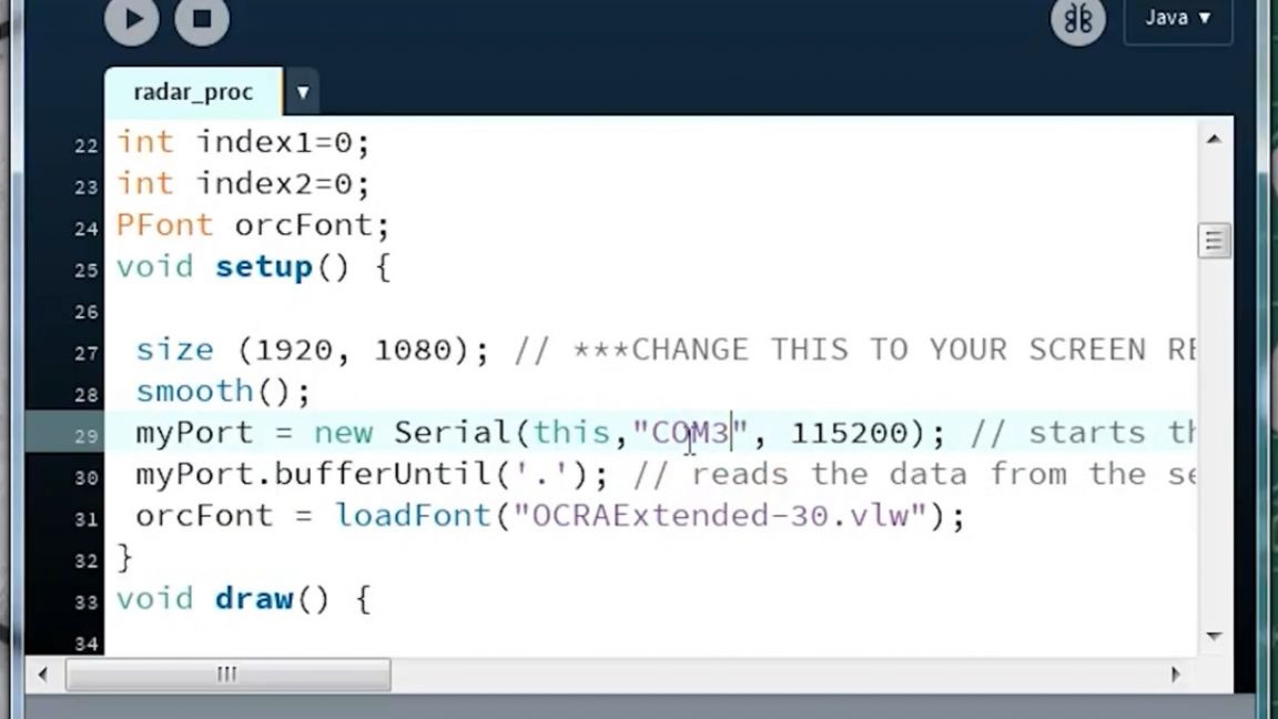
We start.
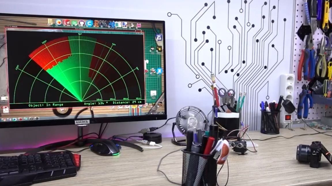
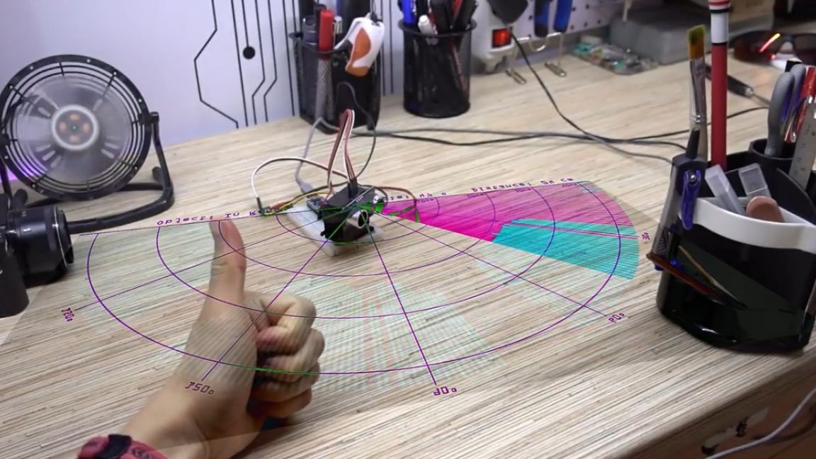
That's it, our radar works great and displays the distance to the obstacles found. As you can see, it works with sufficient accuracy to not only detect a large target in the form of a person or a head, but it also copes with any small things that can become a whole field for interesting experiments. So while everyone is having fun with raspberry pi, I decided to challenge myself and teach a literally blind system to recognize the target and aim at it. This will be a great simple project that can be repeated even with the help of the arduino starter kit. Let’s do it and think over the algorithm of work.
So, the capabilities of the system are pretty much limited. We only get the distance from the radar, but we know which angle each dimension corresponds to. The first thing that comes to mind is building a workspace map. That is, we make one pass and remember at what angle what distance was. Now, in subsequent passes, we can find the difference for each angle according to our map. And thus we can see a new object that will stand out against the background of already known values. Now you need to teach the system to define goals. Let's try this option: we will consider the number of distinguished points that are located one after another, that is, in life, this will be a certain area that the radar scans.
We will consider the goal - the area is larger than a certain size. This immediately filters out all measurement noise. I also propose to forgive the system for several errors when scanning one area, because the ultrasonic sensor is not perfect.
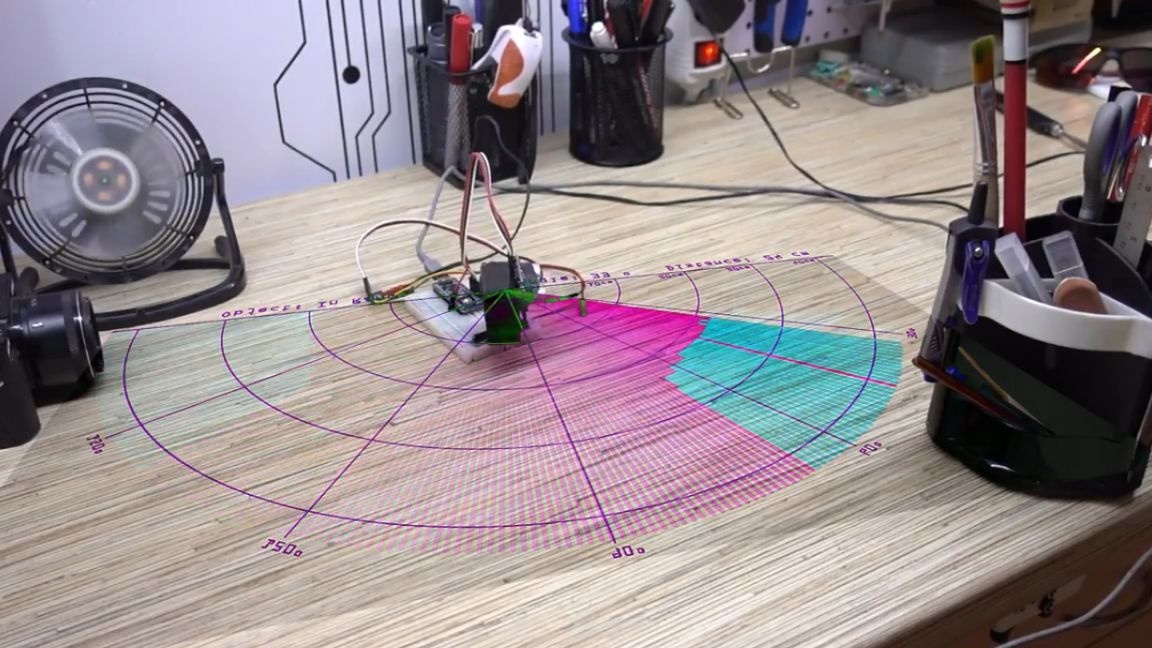
The radar can recognize a large area, that is, it knows the angle of the beginning of this region and the angle of its end in its coordinate system. It remains only to calculate the middle of this area and direct the radar there, and let it no longer move. This will be a hold mode.
We’ll continue to measure the distance and if the measured point suddenly leaves the radar’s visibility range, then after a while we will again switch to the target search mode. That's all who did not understand, the computer is no longer needed here, arduino will do everything by itself. It is enough just to power it from a 5 volt power supply. The firmware lies in the project folder, there is a bunch of settings with which you can play around and configure everything for yourself.
So, we start the system. First, calibration goes from edge to edge. The system remembers the distance in the calibration array in its coordinate system. Then work begins immediately, we scan the area, if we notice the target, then we find its angular size and aim in the middle. It works like a clock and is aimed almost at the center of the target.
By the way, all time delays are configurable, in particular, the time between the loss of goals and the start of a new scan, otherwise you will also think that the system slows down - nothing like that, you just set it up. In general, the brains for the fan are ready, let's collect iron.
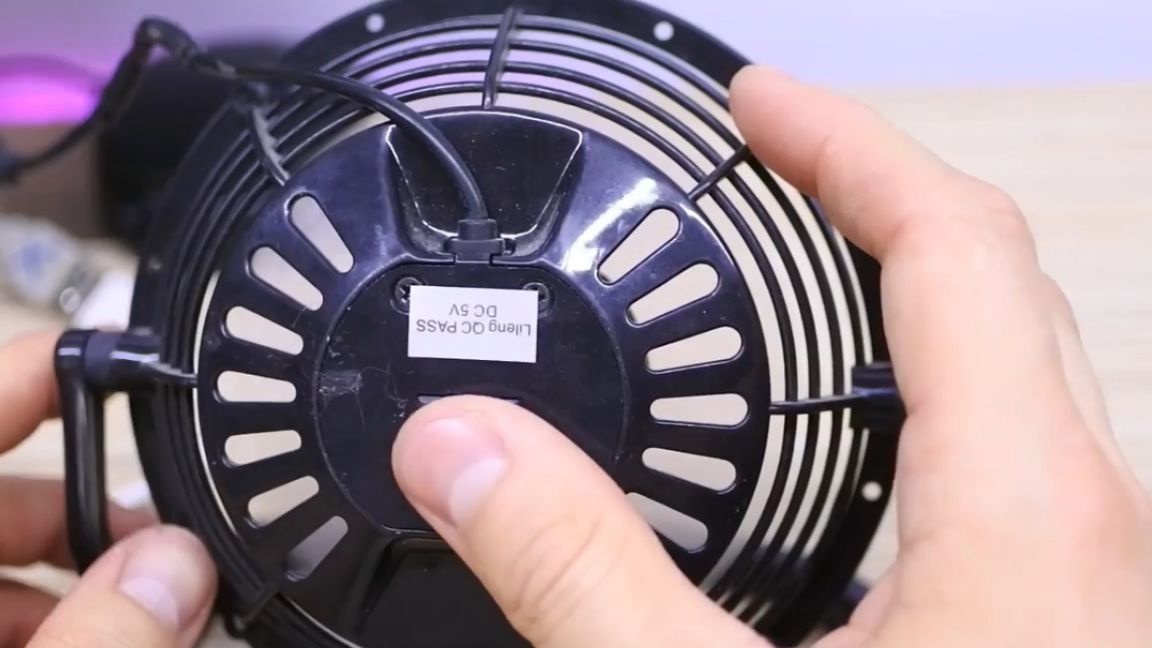
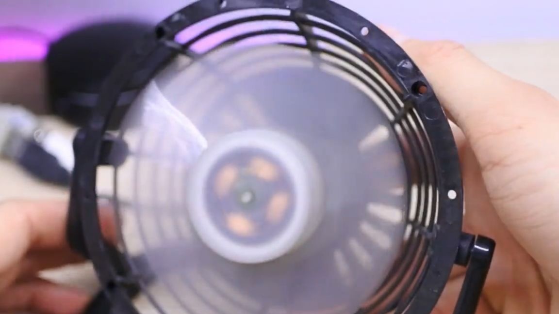
This fan was purchased by aliexpress about 5 years ago. It is compact, powered by USB and is great for this project. You can also search for a usb fan in fix-price or in household goods.
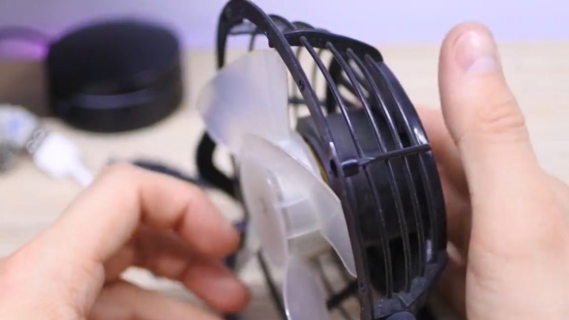
Let's take a look at this fan and see if there is free space in its case that can be crammed with its own electronics.
Arduino nano, unfortunately, does not fit here, but there is an arduino pro mini, the same thing, but smaller and without a programmer on board, but it fits perfectly.
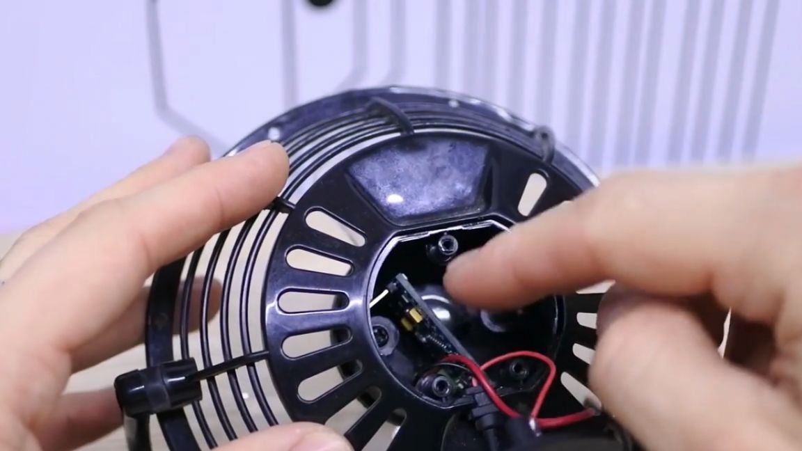
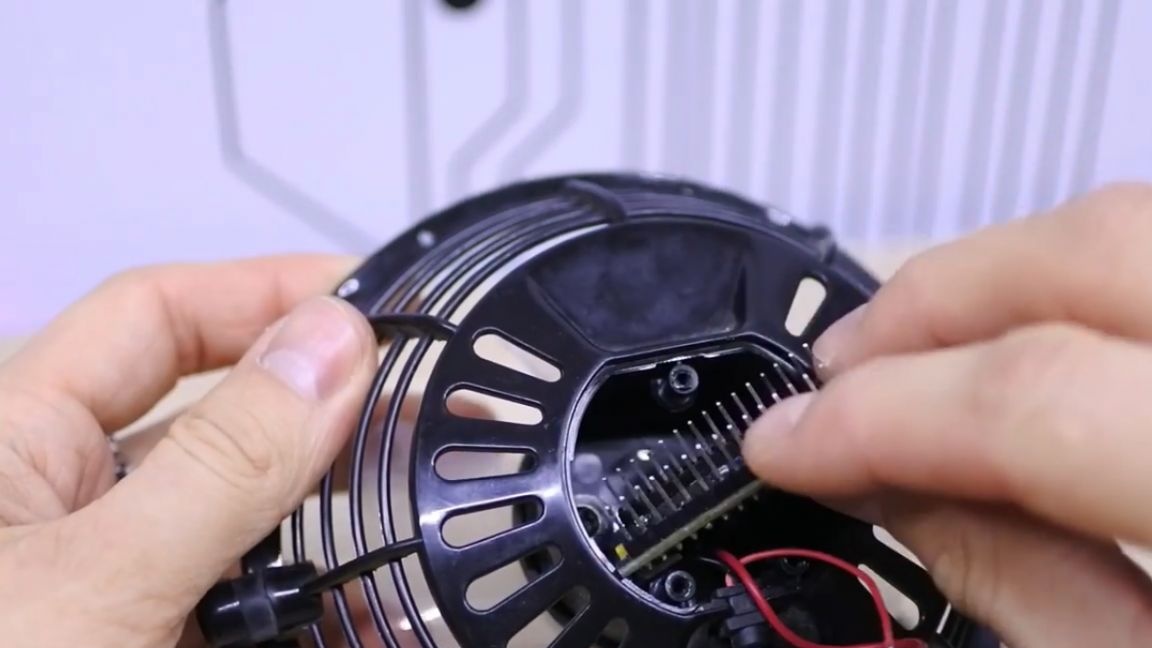
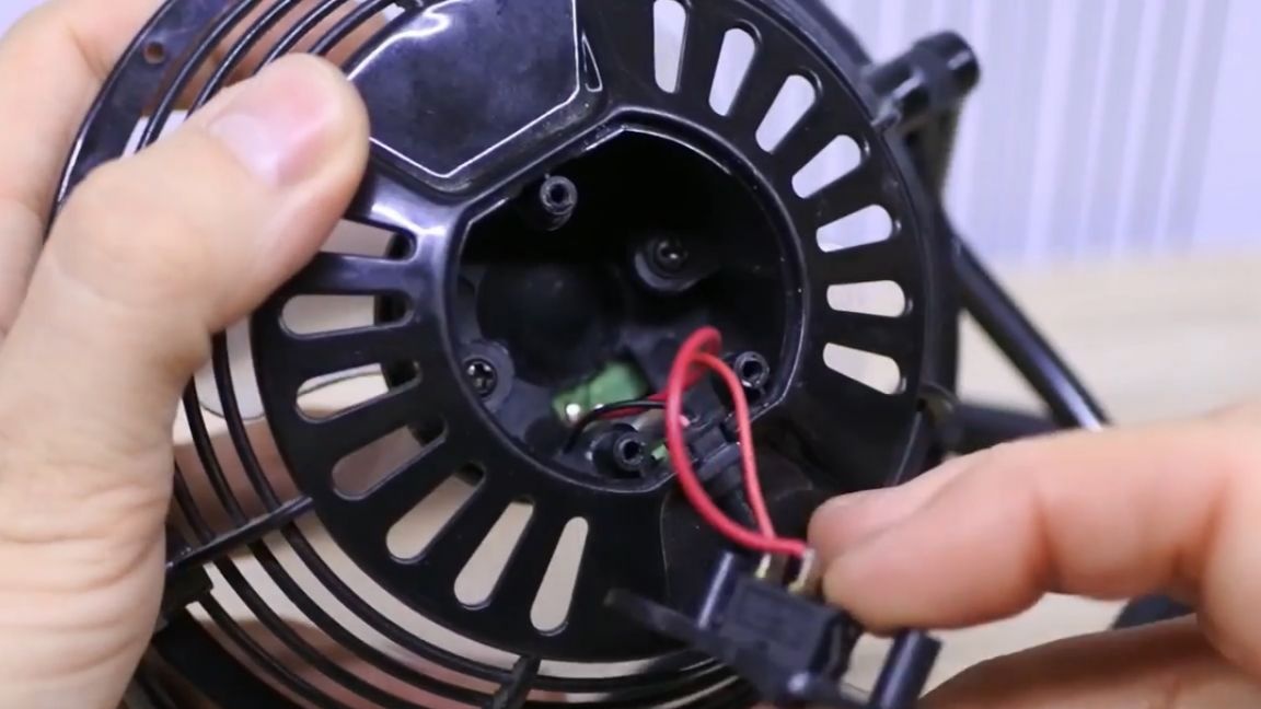
And why not control the power to the fan with the arduino and throw away the native button? There is not enough space, the relay will not fit, so we will use a field effect transistor.
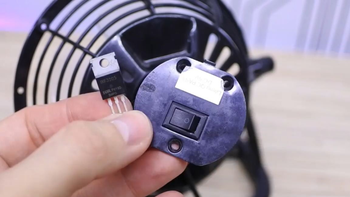
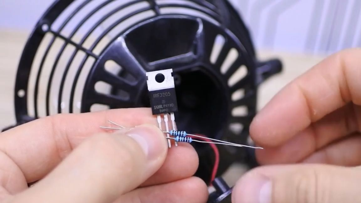
He still needs two resistors of 100 ohms and 10 kOhm. We remove the button completely so that it does not interfere. The connection diagram will look like this:
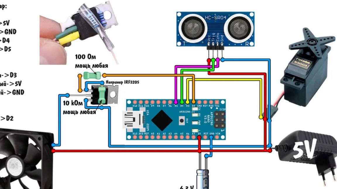
Let's connect the range finder with a cable from the hard drive.
We also have a capacitor in the circuit, it is not necessary, but very desirable, since the servo drive gives quite noticeable current surges for usb, and this can affect distance measurements.
To download the firmware in pro mini, you need an external programmer, it costs the Chinese like a can of beer and connects like this:
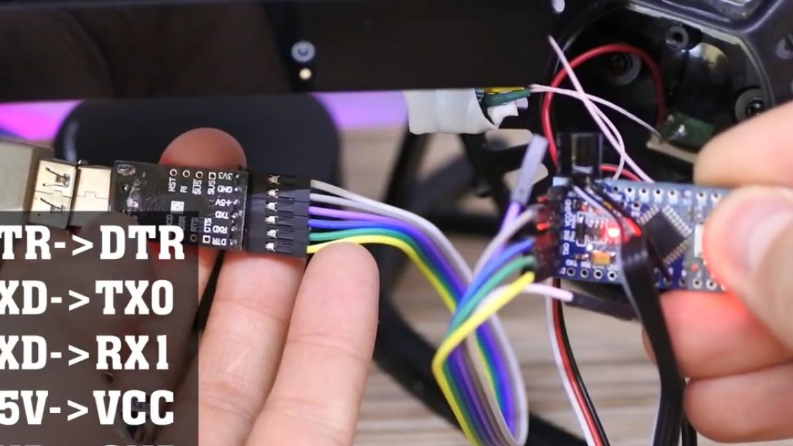
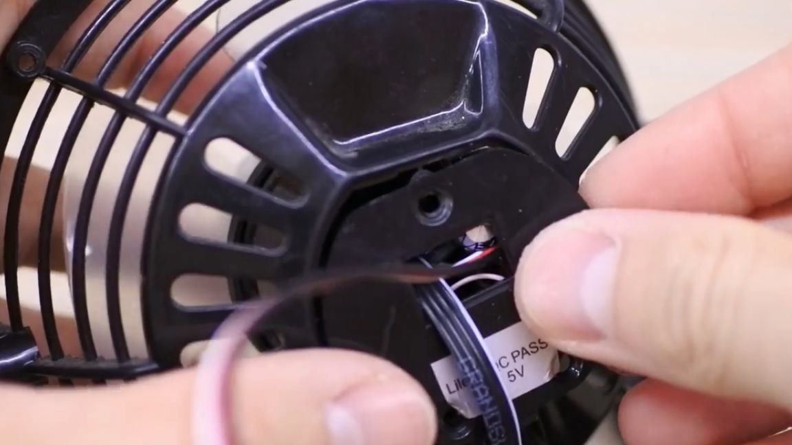
You don’t need to do anything else, click the download button, and the firmware loads as usual into the nano board.The housing closes and all wires exit through the holes from the switch.
Next, you need to fix the servo. It was decided to hang the fan on a shelf, and attach the servo to a corner.
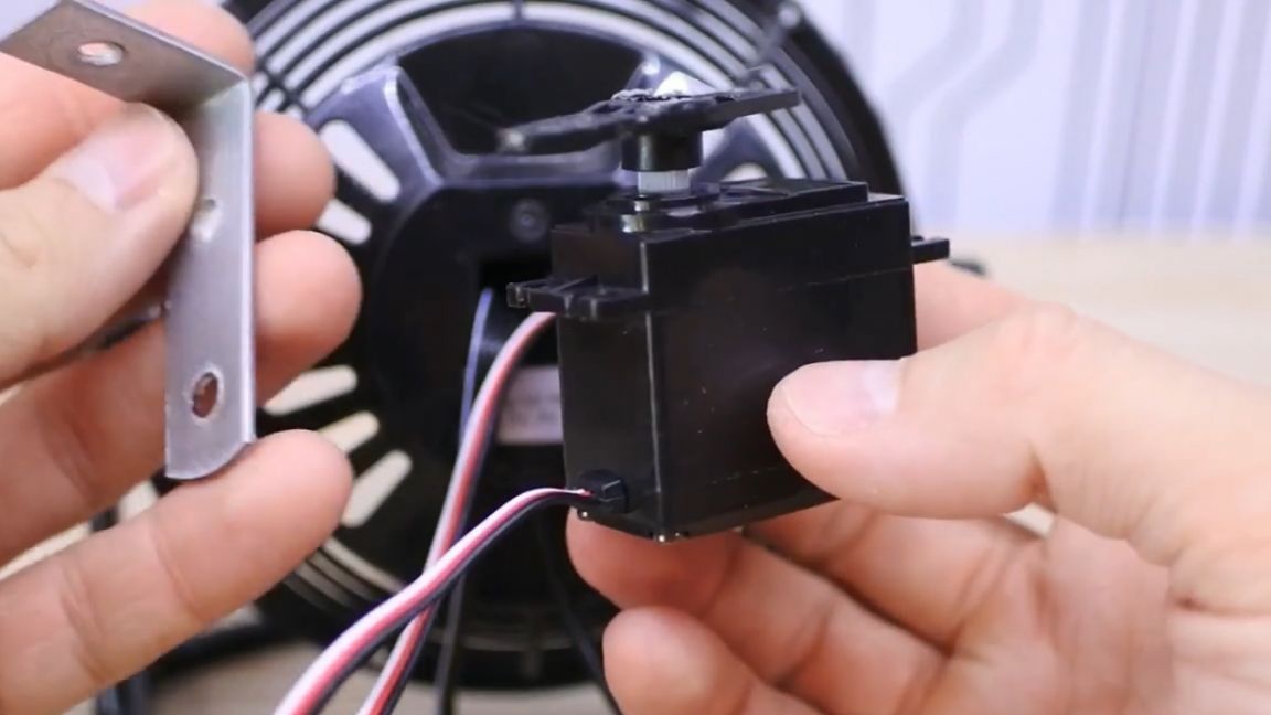
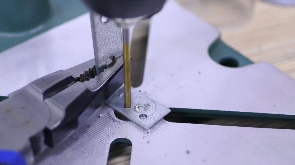
To prevent the corner from spinning, we use double-sided tape, but the elastic from the bike camera would be better.
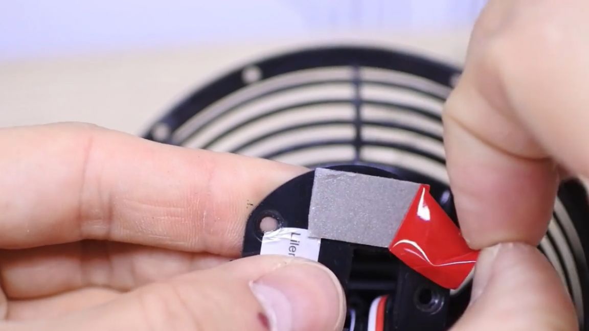
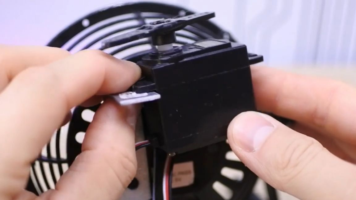
Space for the sensor will have to be slightly expanded. Fix it on the screws that came with the servo.
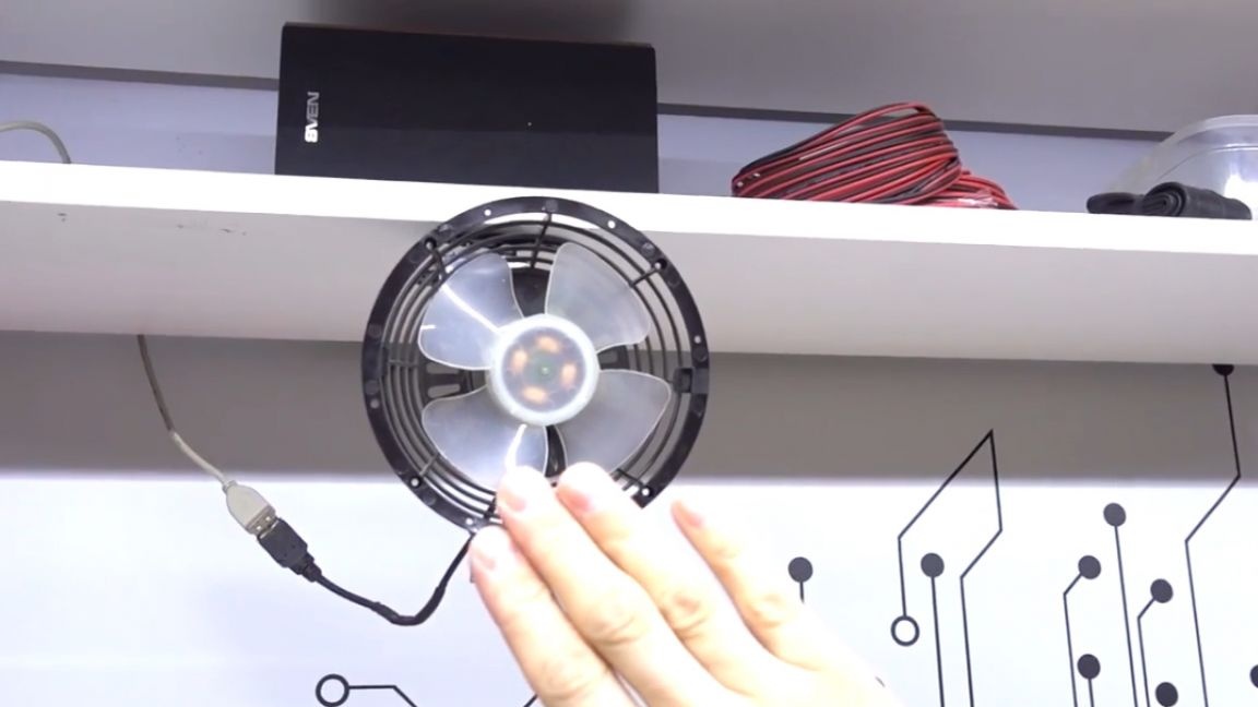
The last touch, everything, turn on and wait for the calibration to pass and enjoy the homing fan.
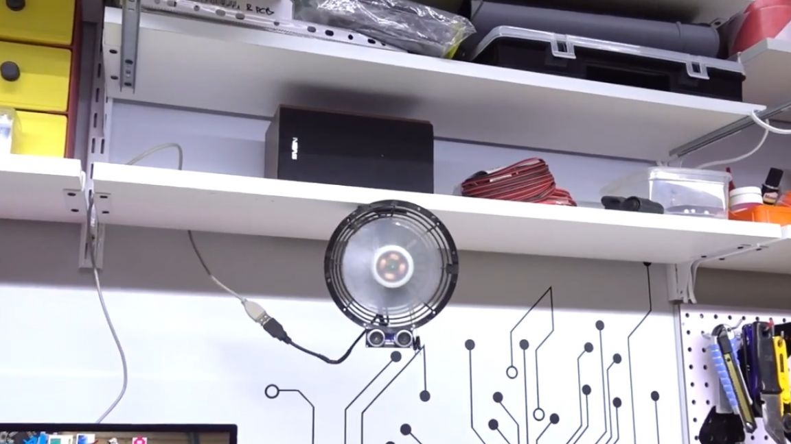
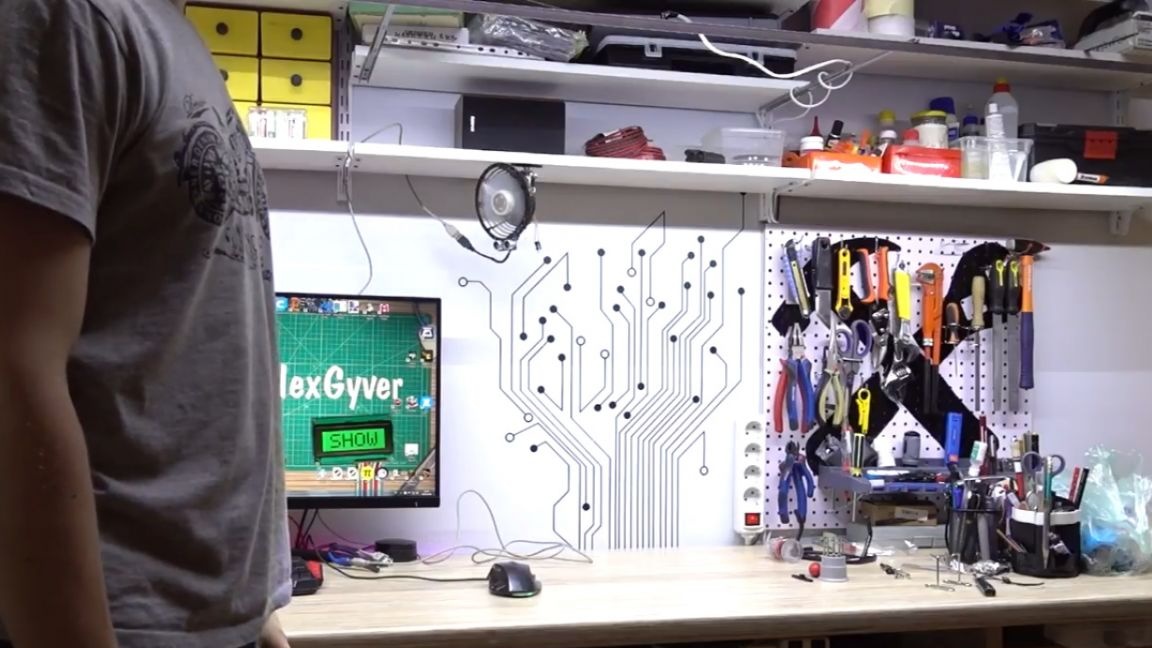
Very funny thing turned out. It was originally conceived as a mock-up, but thanks to the Chinese and a large empty compartment inside the fan, it was possible to make a finished device with almost no protruding wires and snot, which was very pleasing. By the way, if the fan cannot find the target for some time, it rises in the center and turns off. To turn it on, you just need to raise your hand, and the fan is ready to aim at the target and cool it again.
The servo turned out to be cheap plastic, the gearbox hangs all over, so the movement is twitching, but what can I do. On the project page there is a link to a better servo, it has a metal gearbox. The project turned out pretty cool and interesting, due to its simplicity - one sensor, one drive, but as a result, full-fledged homing on the map of the region and touch control.
Thank you for attention. See you soon!
Video: