

I decided to gag myself alarm system and control an electromechanical lock (well, or an electric latch, if simpler).
The problem statement was as follows.
1. Open the gate without mechanical keys.
2. Protect the courtyard at night from those who wish to climb over the fence.
As the old engineer decided to do without the "central" - the main control unit. I don’t need him, and actually the simpler the better. All the devices used in the article were lying at home, acquired by overwork;)
Total list of connected devices.
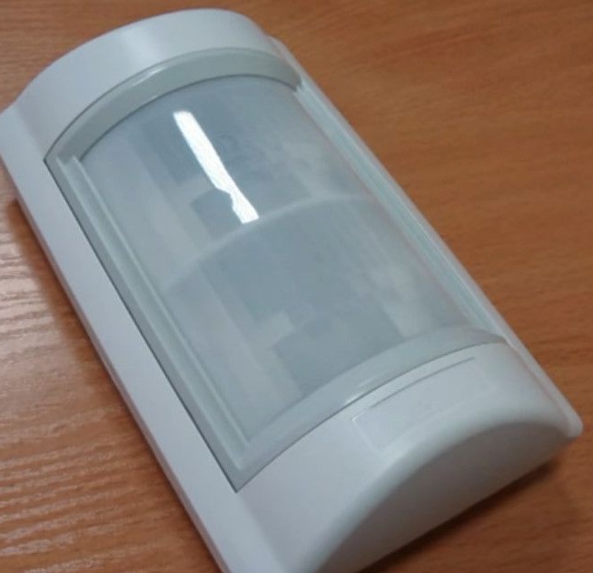
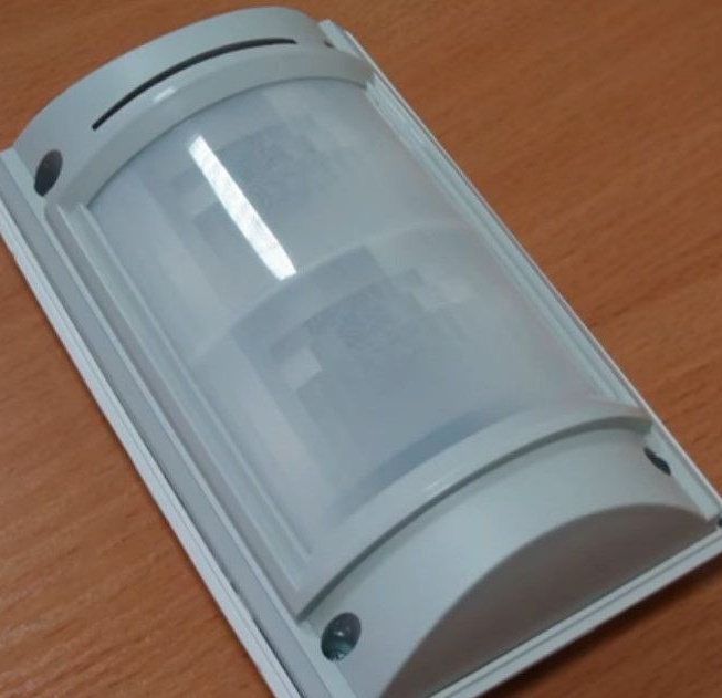
1. Crow D&D street motion sensor (dual technology). Below will be more photos in the clear.
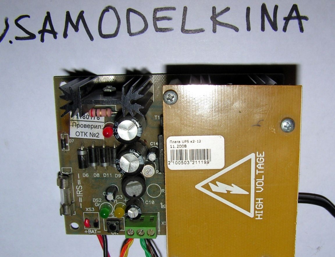
2. Power supply redundant 12V. There is nothing special about the terminals. From left to right. Battery + -. Dead soldered terminal blocks for connecting the battery. The start button from the battery without an input voltage of 220V. The green terminal block + -12V output and the third terminal - a signal of the presence of 220 volts.
3. The Ventura GP12.7 12 Volt rechargeable battery is 7 Amp-hours (those which are used in the security alarm system, computer uninterruptors and scooters). For an example I show two different.


4. Panic button - remote controls. The small button is the opening of the lock. Big button - turn on and off the light and sound alarm.

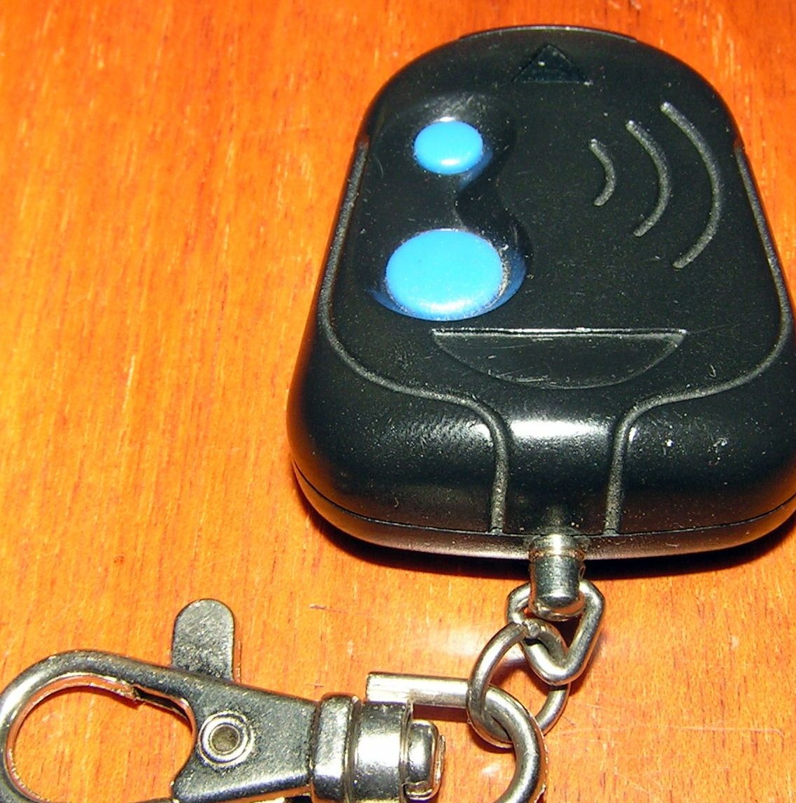
with GSN ACS-102 receiver for 2 relays.

5. A pair of bits of twelve-volt LED strips.
6. Mortise door open sensor. It works when you bring the magnet 3 centimeters. Closes the contacts.

7. A pair of 12V reels. As a result, I managed without them, but if you need to connect additional devices, then they can come in handy.
8. A coil of wires 10 * 0.22 (a twisted pair cable would have been enough, but alas. That was).
9. Capacitor 4700 * 16 or more.
10. Tweeter 12V type BUZZER with a self-oscillator.

11. Iron boxing.
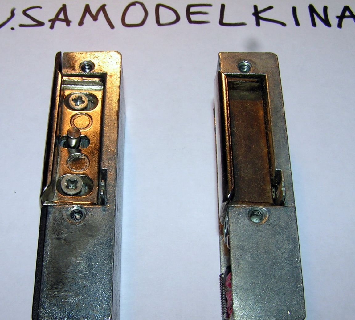
12. The electric latch. Again, showing two different. The first - with the fixation of the opening, the second - without. In short, if the door was not opened during the first power-up, it will remain open.
So, let's begin.
The ACS-102 receiver has two relays - control channels, each of which is rigidly attached to its button on the remote control. At the same time, the operating modes of the channels are programmed separately.
In my case, it is necessary to supply power on the first channel for a short time. He will control the opening of the electric latch. I programmed for about 4 seconds.Why not a short-term impulse - I will explain later.
For the second channel, you just need to switch the relay. It will enable and disable the burglar alarm. On - sound and light indication is activated. Off - only the motion sensor works.
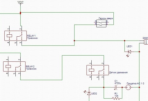
The scheme will consist of two blocks - one is installed inside the house, the second on the street.
Brief outline. On the left are two relays of the receiver installed in the house. To the right is the entire street commutation.
The composition and purpose of the first block.
Since the whole system needs 12V power, I will install the power supply itself, which converts 220 to 12 volts, closer to the electrical panel.
And also in the presence of an electric lock that opens only when power is supplied, it must be reserved. The backup will be carried out using a 12-volt UPS K2.12 power supply and a Ventura battery.
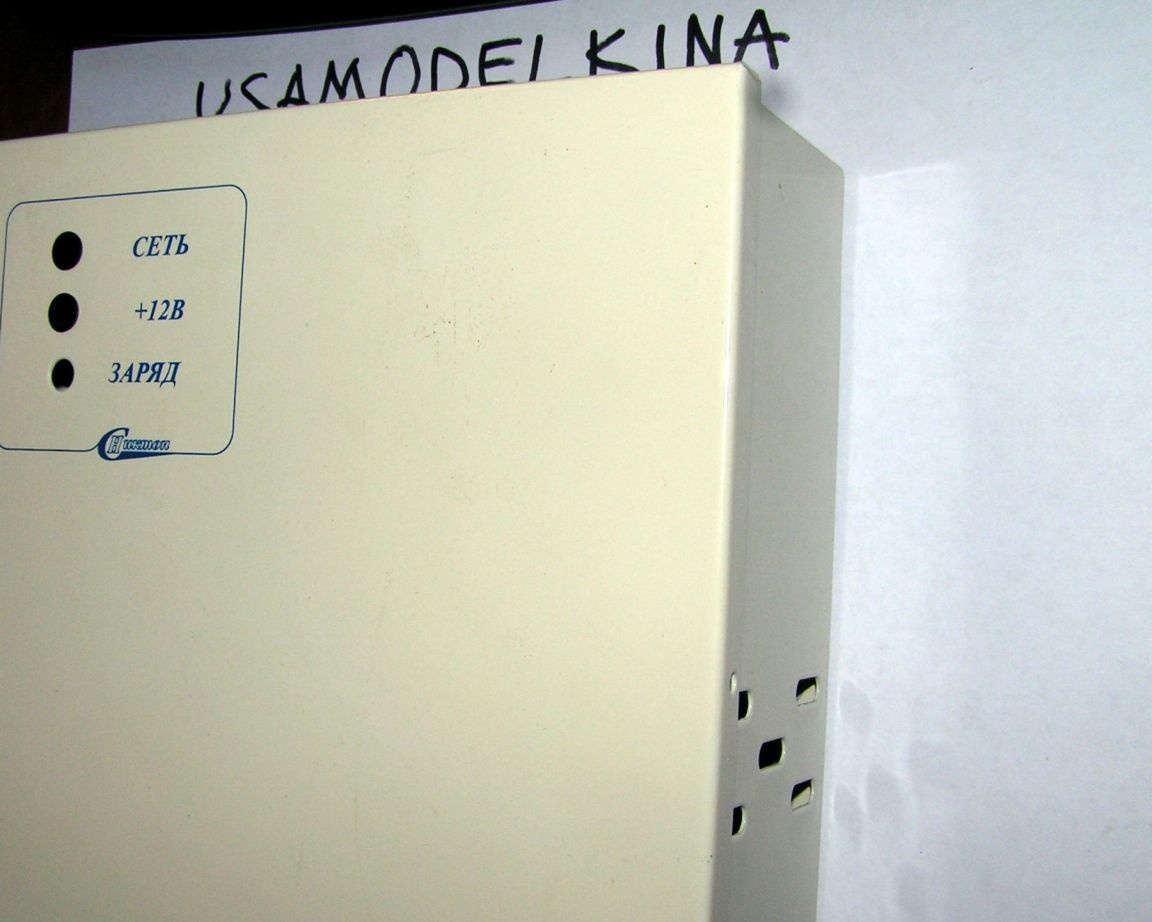
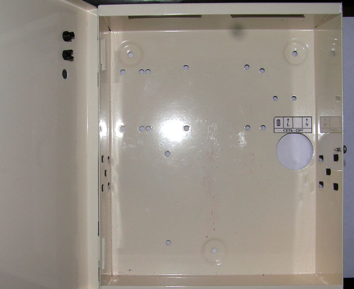
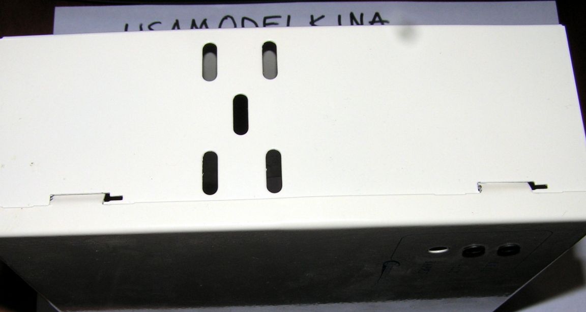
I will install these comrades, not only for glamor, but also for fire safety (220 is supplied to the power supply unit) in an iron box.
Also, near the box, I install a GSN radio. Why outside? At first. The frequency at the radio is 433 Megahertz, and it simply won’t work from a piece of iron. You can of course bring the antenna out of the iron case, but here's the second. I need an indication of the receiver itself. I will tell about operating modes, skills and programming thereof below.
Street block.
Not quite a block, but a larger switching box and motion sensors. I just need one sensor type "volume", or infrared motion sensor, anyone.
By inheritance from one collapsing company, I got a lot of all kinds of equipment. So using Crow D&D is a street-performance motion sensor. It monitors the protected area in the infrared range using two separate dual PIR sensors. Signals are processed by the ASIC microcontroller. It has temperature compensation, and the wide-angle Fresnel lens used creates a protected area with an angle of up to 105 degrees. Range - up to 18 m.
You can use almost any similar one, you can even play around with active street lighting systems, you can also get the desired signal from them.
Further. The simplest sound indication system was built from a capacitor and tweeter. I turned them on in series, and a 10KΩ resistor parallel to the capacitor so that it discharged. When applying power to such a design - it emits a nasty piiuuu while the capacitor is charging. And falls silent. Turning off the power for 5-10 seconds leads to the discharge of the capacitor through the resistor. If you turn on the power again, a sound is made. This is done so that the sound is more interesting and there are no deafening sounds during repeated triggering of the motion sensor. Enough initial loud.
Actually, we connect power to this design SEQUENTLY:
1 through the output from the sensor, which is normally open.
2 second radio relay.
Lock control.
Everything is simple here too. connect 12V in series.
First receiver relay, normally open contact and lock.
Parallel! to the first relay we connect the sensor * number 6 in the list *
With it, even if you forget the radio keys or the batteries sit in them, you can open the door with a magnet. To do this, we wrap the sensor anywhere near the door to the wall. I did it right in the seam between the cinder blocks. And coated with cement. Now, even a keychain does not need to be taken with you. I handed out to the relatives the usual magnets from the children's designer, and said where to put it so that the door opens.
And I use remote controls at home so as not to run to open the gate.
When installing the latch, I specially made it so that the door pressed it a little, and remained closed if it was not pressed down a bit. Accidental button presses will not open the door.
Indicators.
LED1 Green Ribbon. Install outside the door, shows the opening of the lock. It works both from the remote control and when the magnet is brought to the opening sensor.
LED2 Red Ribbon. It can be installed anywhere you see the indicator at night. I just duplicated the indication of the motion sensor, and put it next.
Yes. forgot to indicate in the scheme. In parallel with the power of the motion sensor, I put another LED strip - white. I use it as an indicator of arming, and at the same time as lighting near the gate.
I disassemble the motion sensor.
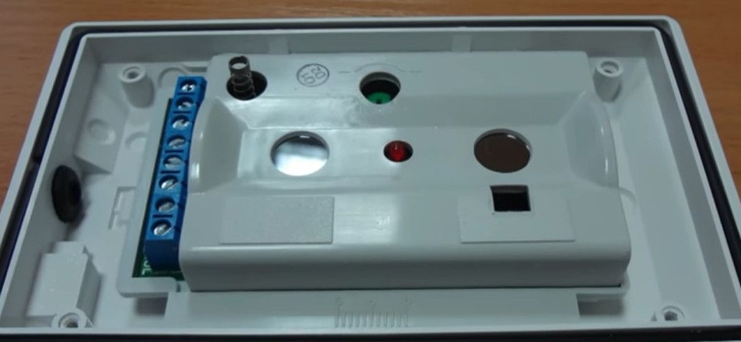
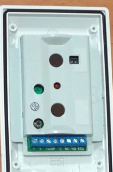
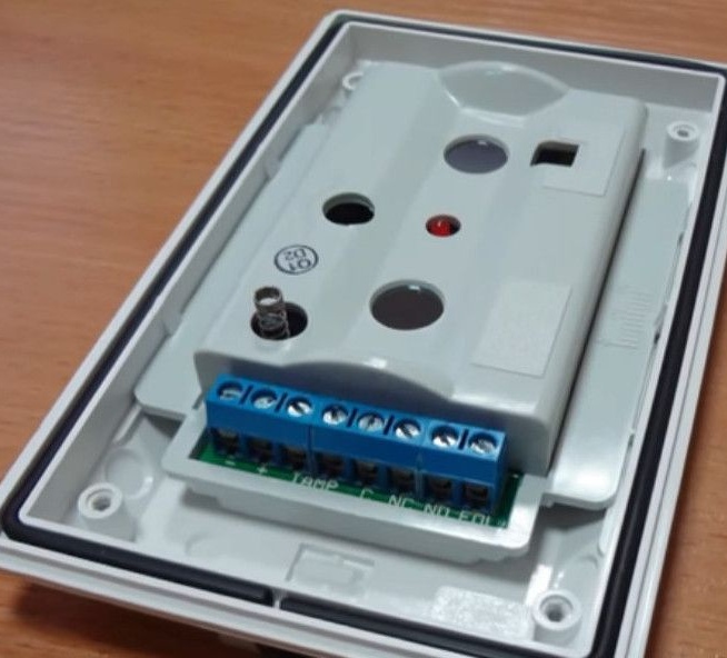
Terminals from left to right.
1- and 2 + 12V power
TAMP 2 and 4 - or tamper, normally closed contacts of the sensor housing opening. Do not use.
5 common relay contact
6 normally closed and
7 normally open relay contact.
8 do not use.
We deal with the receiver. There are 2 options for schemes, with one
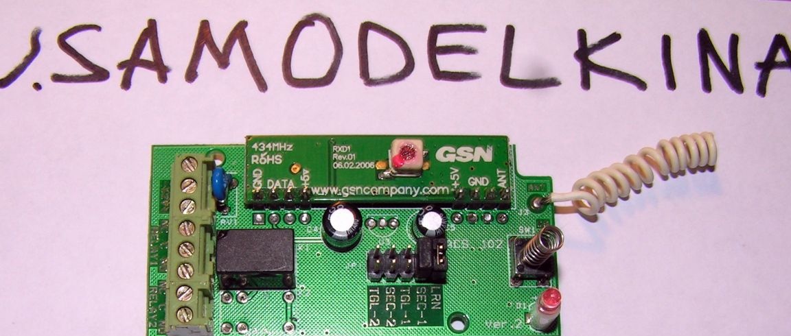
and two relays. And connect it.
Attention to jumpers! These are the operating modes of both relays. Only the last one needs to be removed.
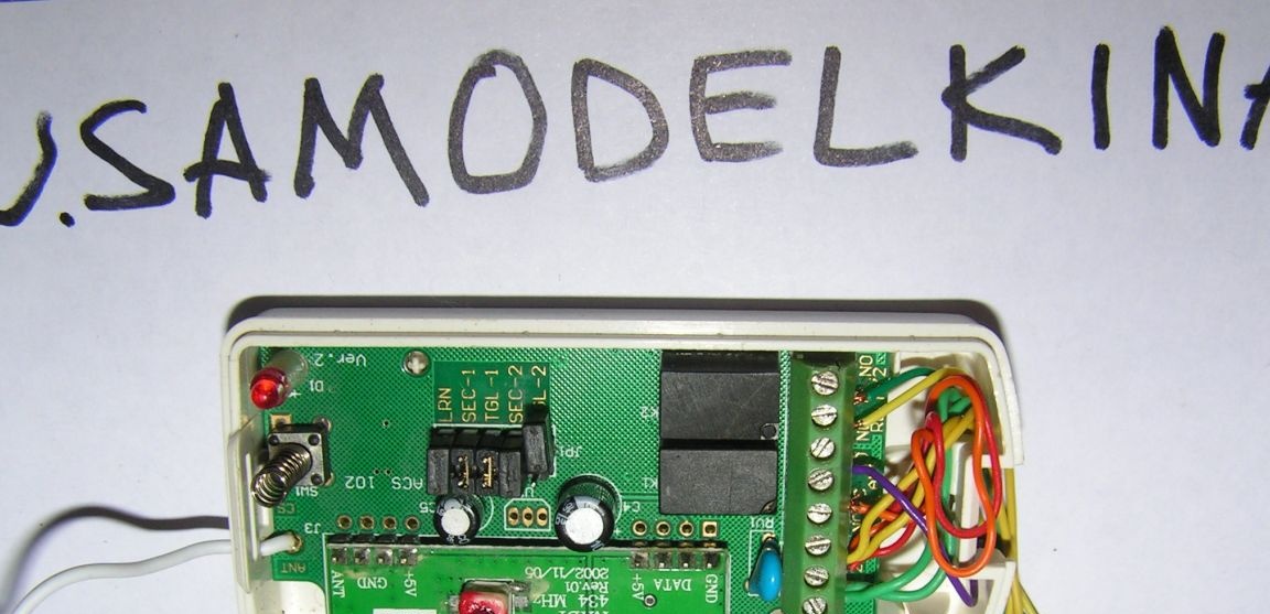
Terminals from left to right.
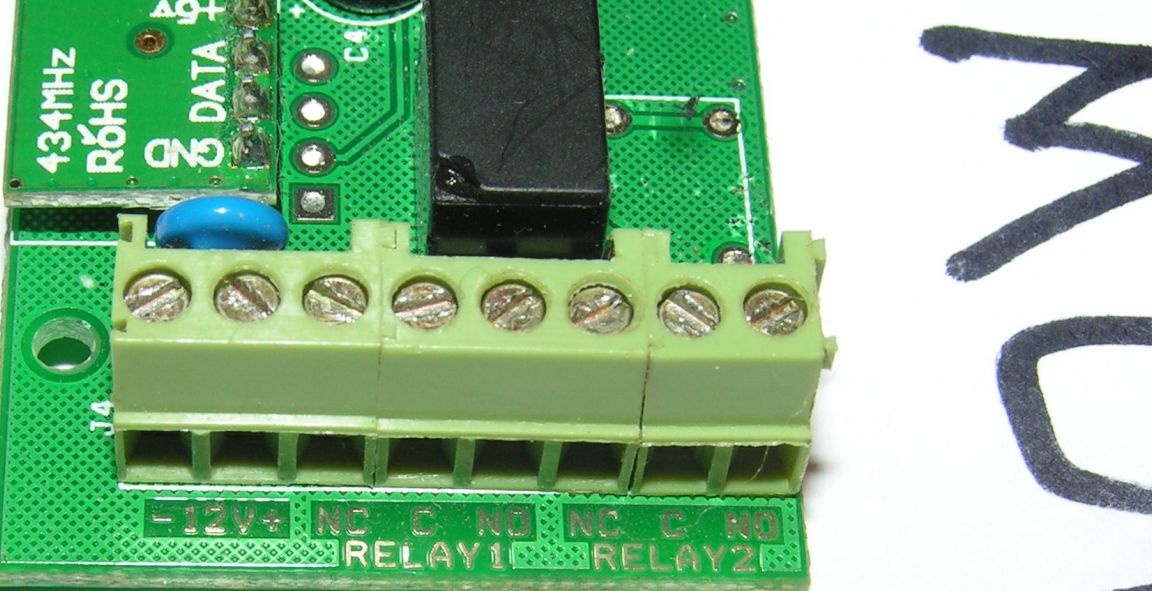
1- and 2+ meals
relay 1
3 normally closed
4 general
5 normally open
relay 2
6 normally closed
7 common
8 normally open
Latch in open form.


The principle of operation is very simple, the tongue of a conventional door handle is fixed to it when the door is closed. In this case, we remove the outer handle. In its place we put an ordinary, not inclined.
Well, iron boxing in the open.
Like that’s all. All good homemade!