
Hello to all lovers homemade. In this article I will tell you how to make an ammeter do it yourself, in the assembly of which the kit kit will help, a link to it will be at the end of the article. This ammeter is useful for various homemade products where you need to control amperage. The body of the radio designer is made specifically with latches for installation on a shield or panel, which is a definite plus.
Before reading the article, I suggest watching a video with a detailed assembly process and checking the operation of the kit.
In order to make an ammeter with your own hands, you will need:
* Kit
* Soldering iron, flux, solder
* Multimeter
* Device for soldering "third hand"
* Crosshead screwdriver
* Side cutters
Step one.
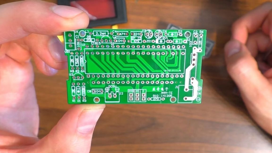
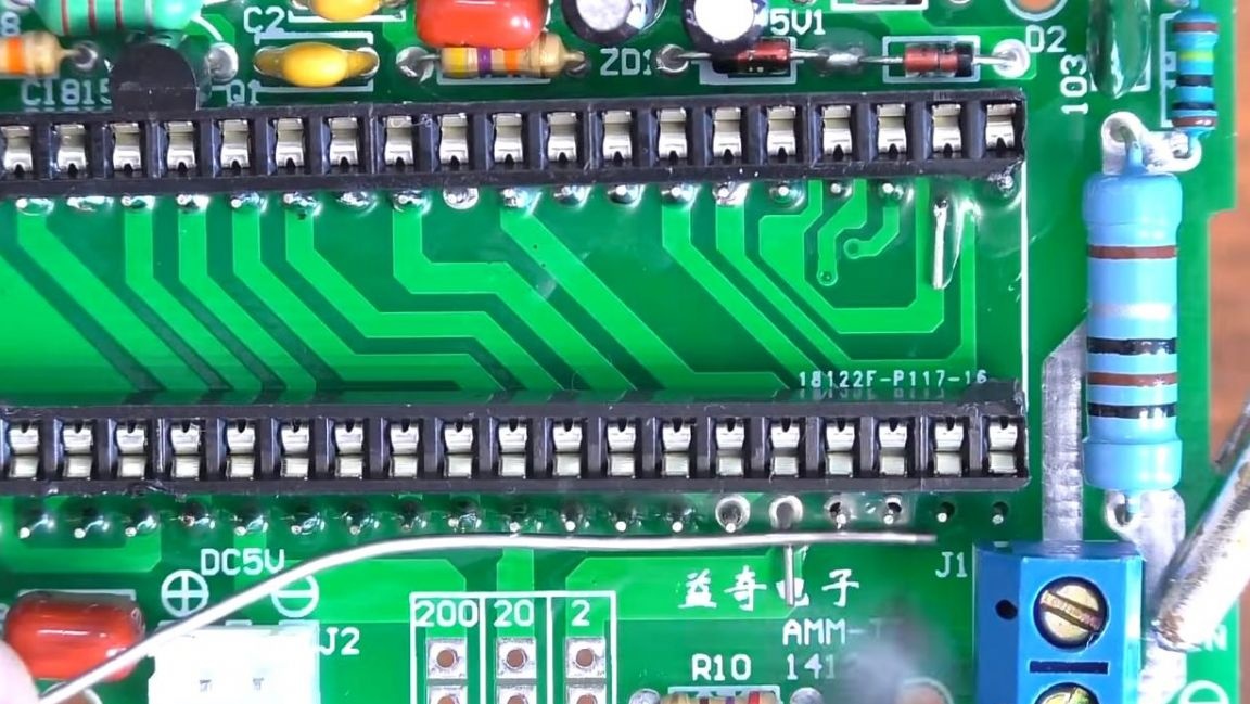
All installation will be carried out on a printed circuit board on which the marking of all components is applied, so that in this case the instruction is not needed, the quality of manufacture of the board itself is at a high level, it also has metallized holes.
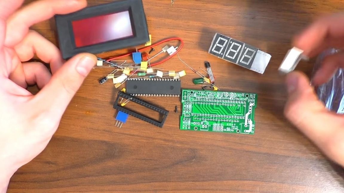
In addition to the board itself, there are not many radio components, such as capacitors, a microcircuit and a socket under it, a case with a red filter and other components.
Having dealt with the kit kit, go directly to the assembly.
Step Two
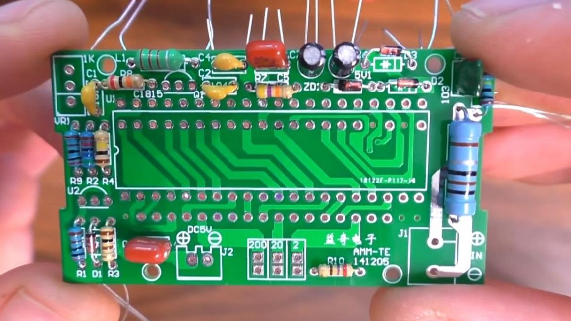
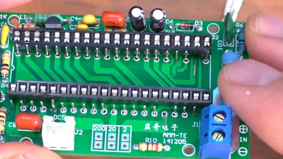
First of all, we install resistors on the board. To install resistors, you need to measure their values, you can do this with a multimeter, color coding with a look-up table or an online calculator. Having determined the resistance of each resistor, we install them in their places, according to the marking on the board, on the reverse side we bend the conclusions so that the parts do not fall out when soldering.
After installing the resistors, we go to the capacitors, install the polar and non-polar capacitors, set the polar ones in accordance with the polarity, plus this is the long leg, minus-short, also minus on the board is indicated by a shaded semicircle.
We insert non-polar ceramic capacitors according to the digital marking on their case and on the board itself. Next, insert the diodes, on the board one of them is highlighted with a bold strip, which is also printed in black on the diode case, the other three are all the same and it will not work out to mix them up, and then set the inductance.
Step Three
Now we fix the board in the “third hand” soldering device and apply the flux to the contacts, after which we solder them with a soldering iron, adding solder as needed.
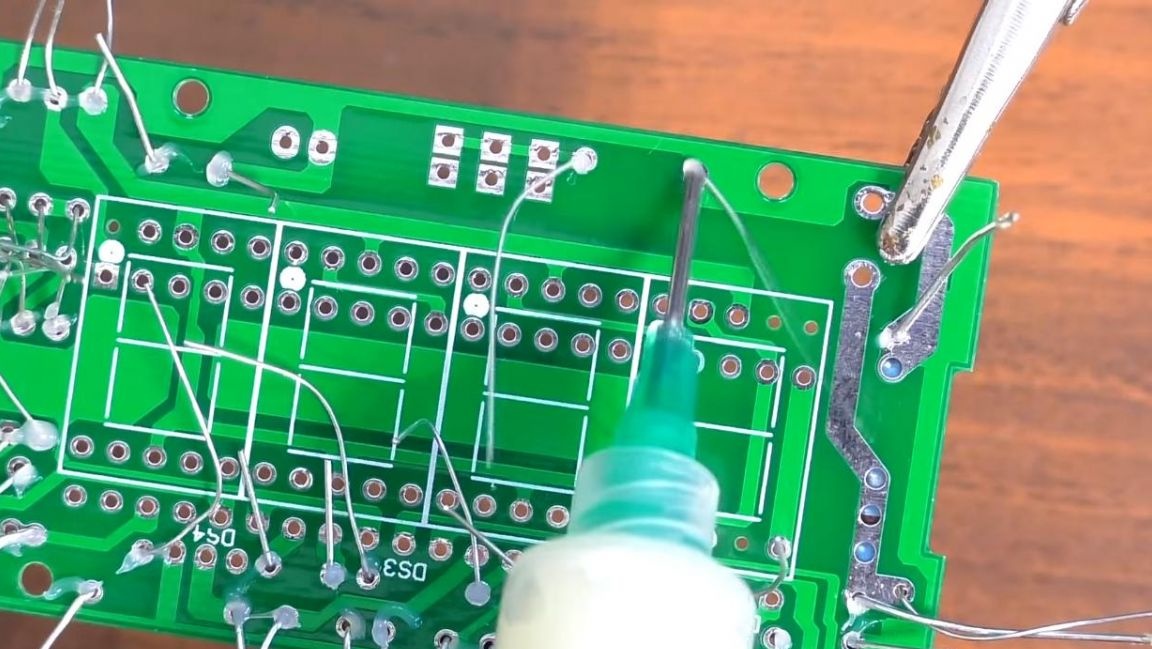
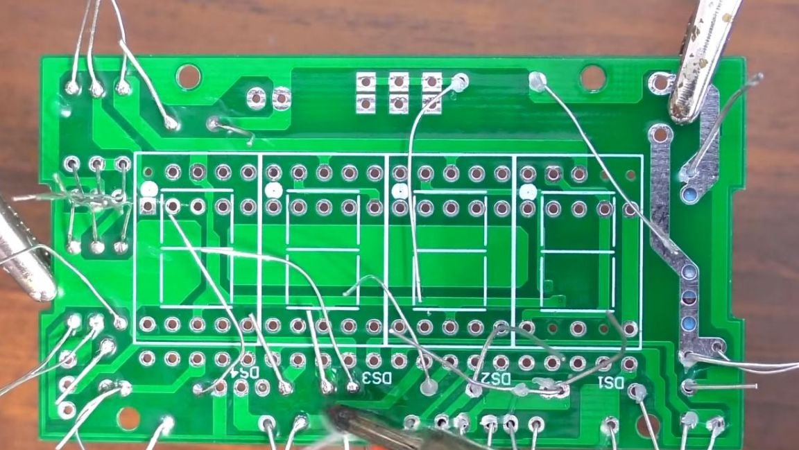
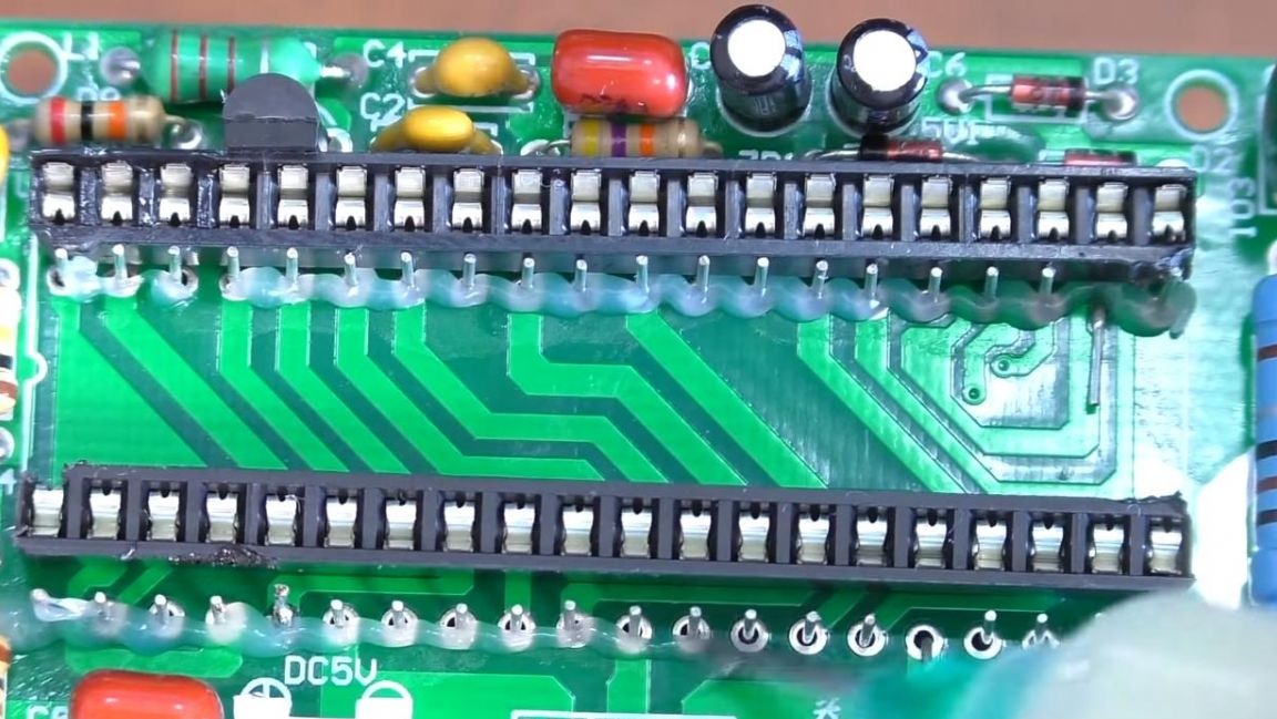
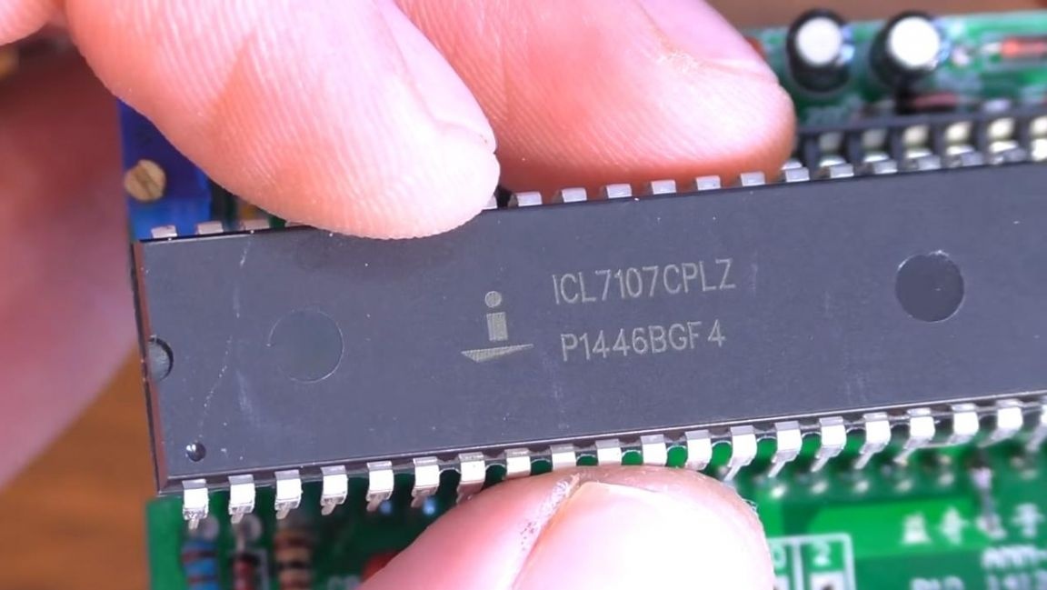
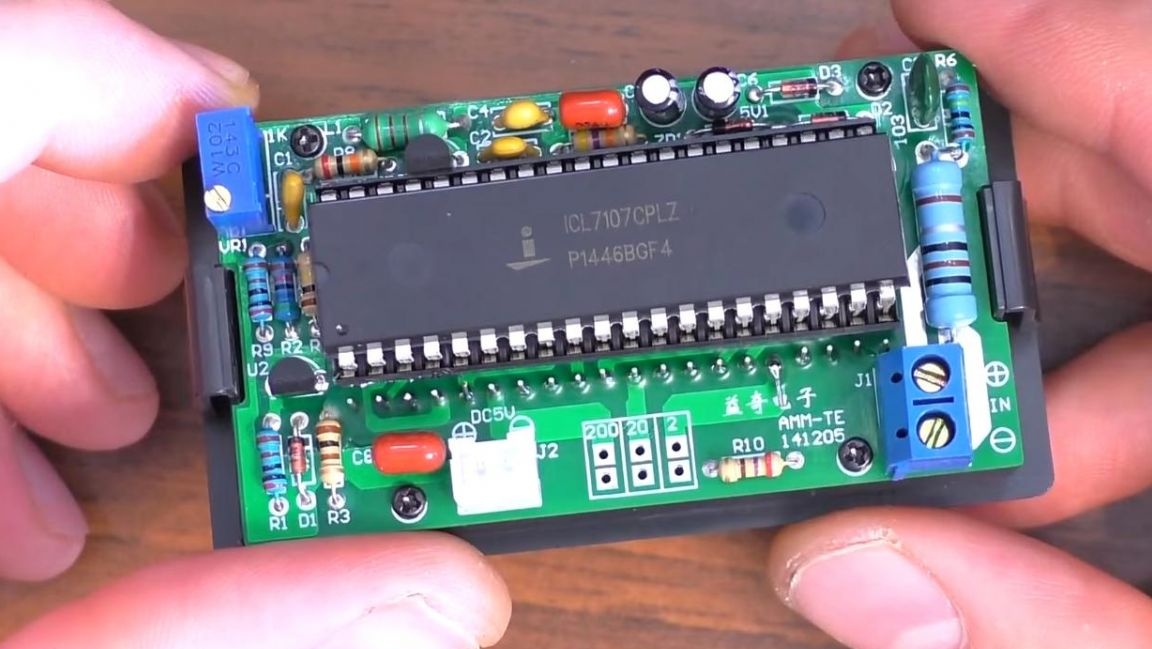
Next, with the help of side cutters, bite off the extra part of the conclusions so that they do not interfere in the future. When removing the terminals with side cutters, be careful, since the tracks on the board do not hold very tight and there is the possibility of accidentally tearing them off. After that, install the remaining elements. We insert a panel on the board for installing the chip, focusing on the key, then two transistors, the board shows the marking in the form of their cases. To calibrate the device, we install a tuning resistor, and insert the connectors for connecting the input and output.
We solder the installed radio components on the back of the board with a soldering iron, similar to the previous step.
Step Four
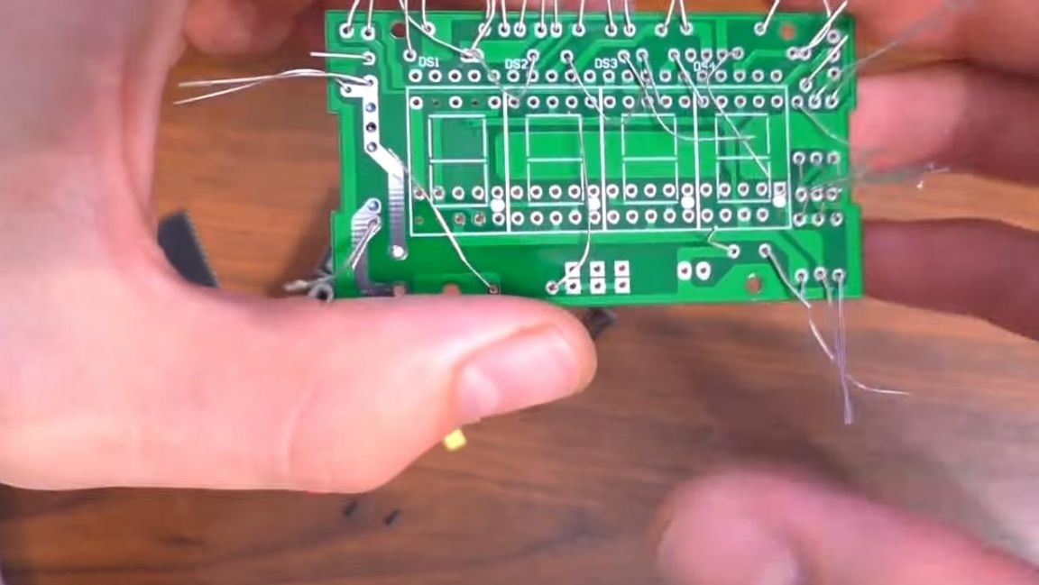
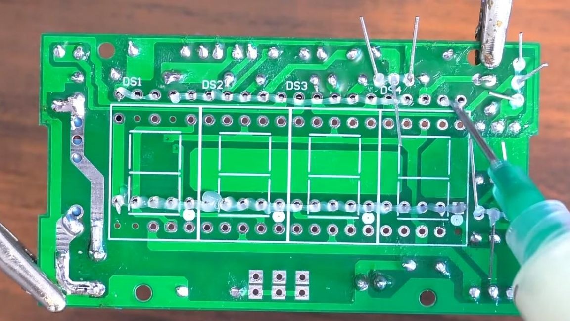
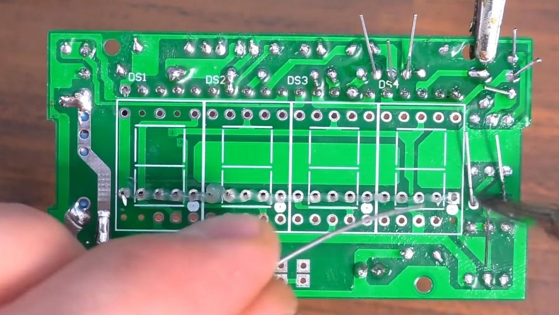
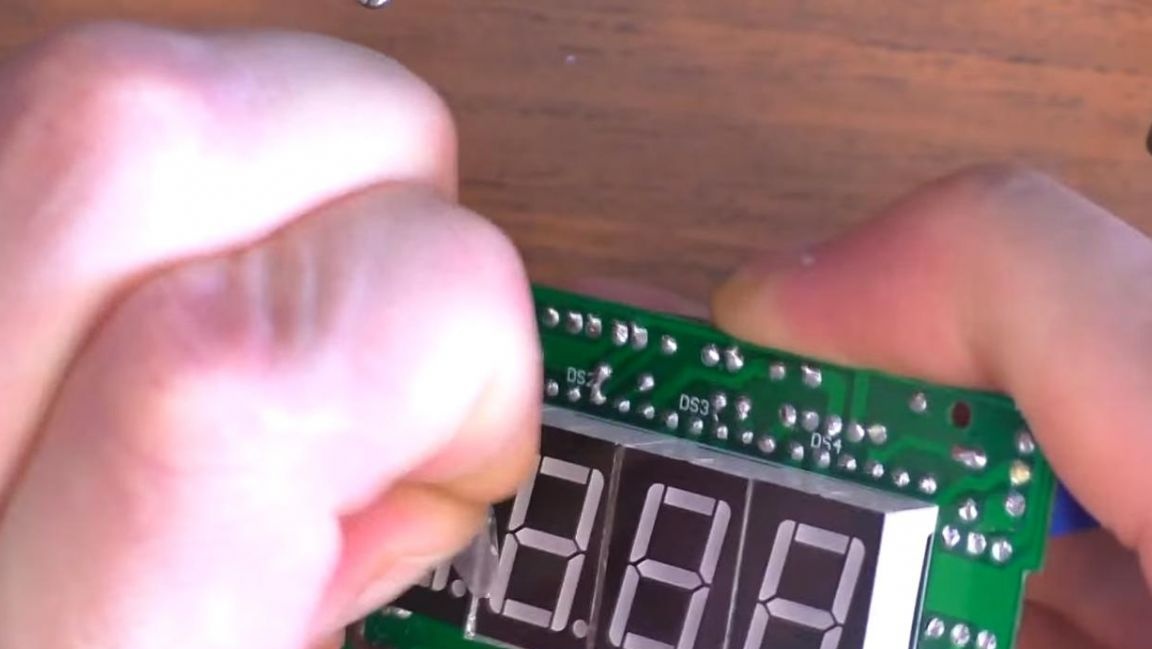
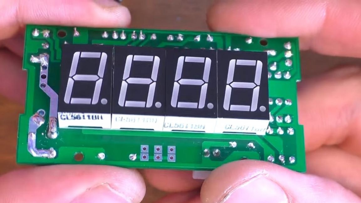
After soldering, we insert seven-segment indicators on the board, focusing on the point on their case and on the board's markings, but before that we clear the board of flux residues, for this solvent or galosh gasoline is perfect.
We fix the board in the "third hand", apply the flux and solder the conclusions of the indicators, while trying not to overheat them.
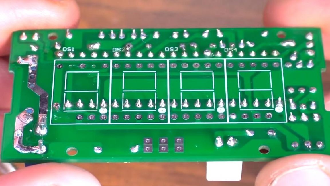
It is not necessary to delete conclusions at this stage, since they do not interfere.
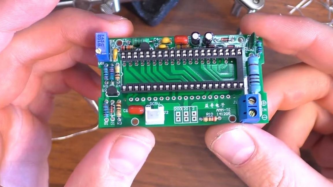
We insert the microcircuit, guided by the key in the form of a semicircular recess on its case, as well as on the board itself.
Peel off the protective film from the seven-segment indicators.
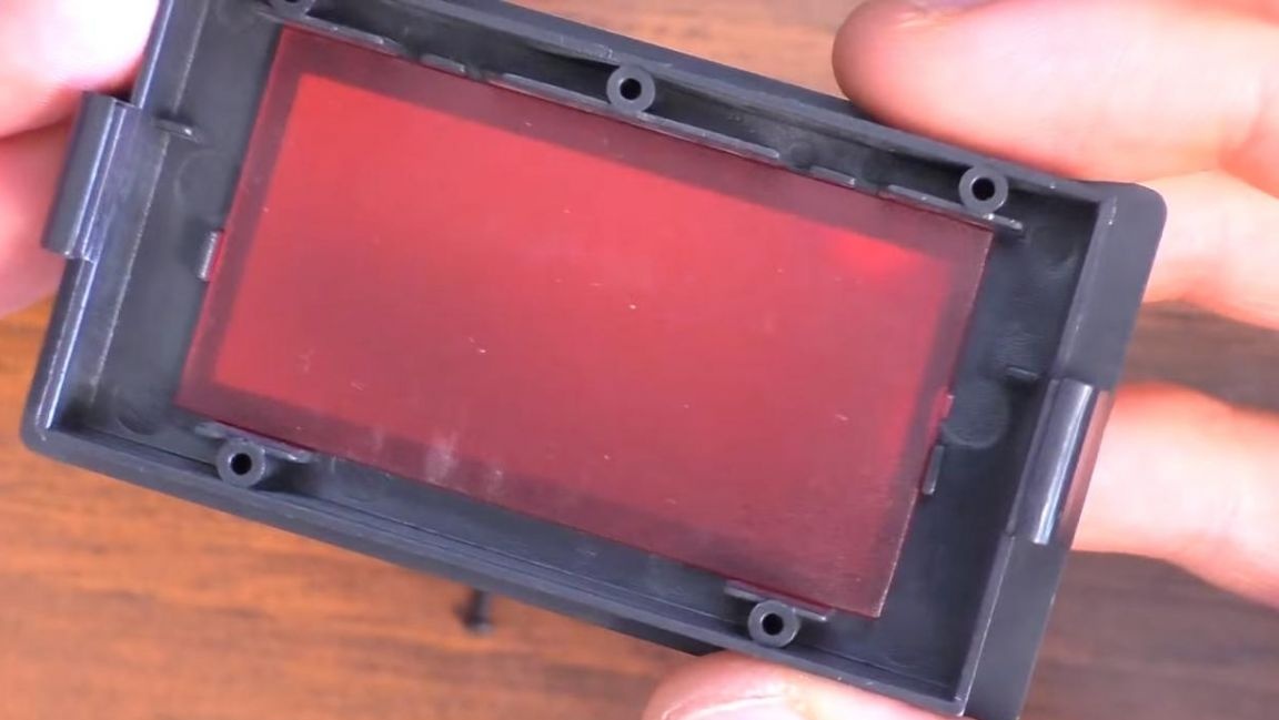
Then we install the assembled board in the case with a red filter, which serves as an anti-glare.
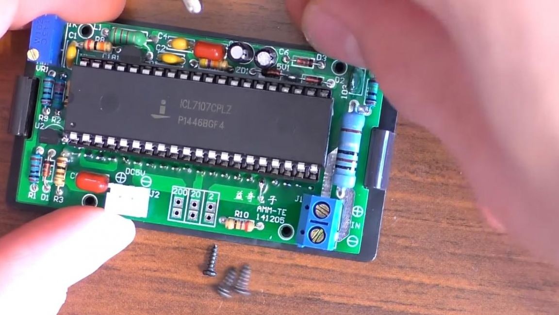
We fix the board in the case with the help of four screws of their kit, screw them with a Phillips screwdriver.
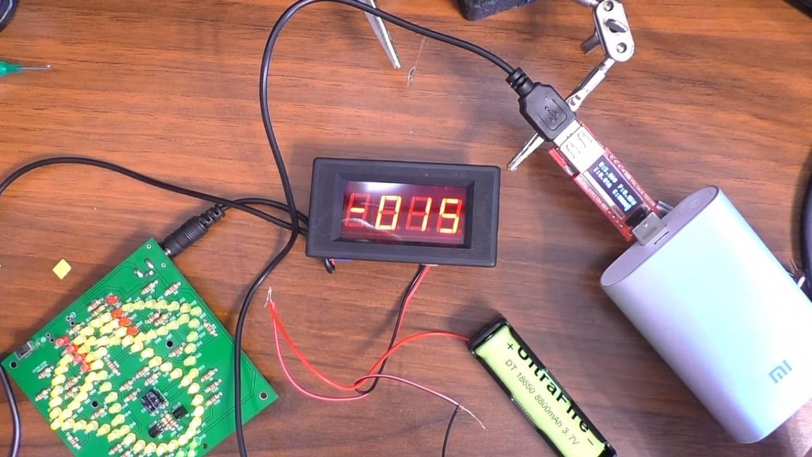
So the kit kit is ready, now it can be checked in action.
Step Five
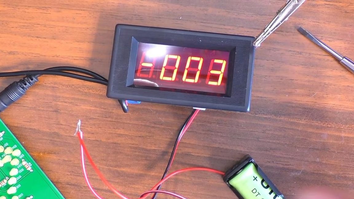
To check this radio designer, it is necessary to connect the wires to the power supply, a 18650 battery will be enough for this, and the device under test is connected in gap to the input of the device.
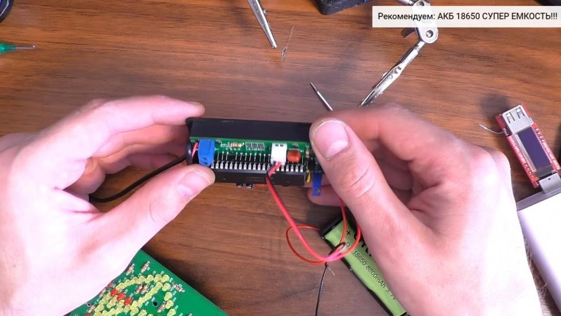
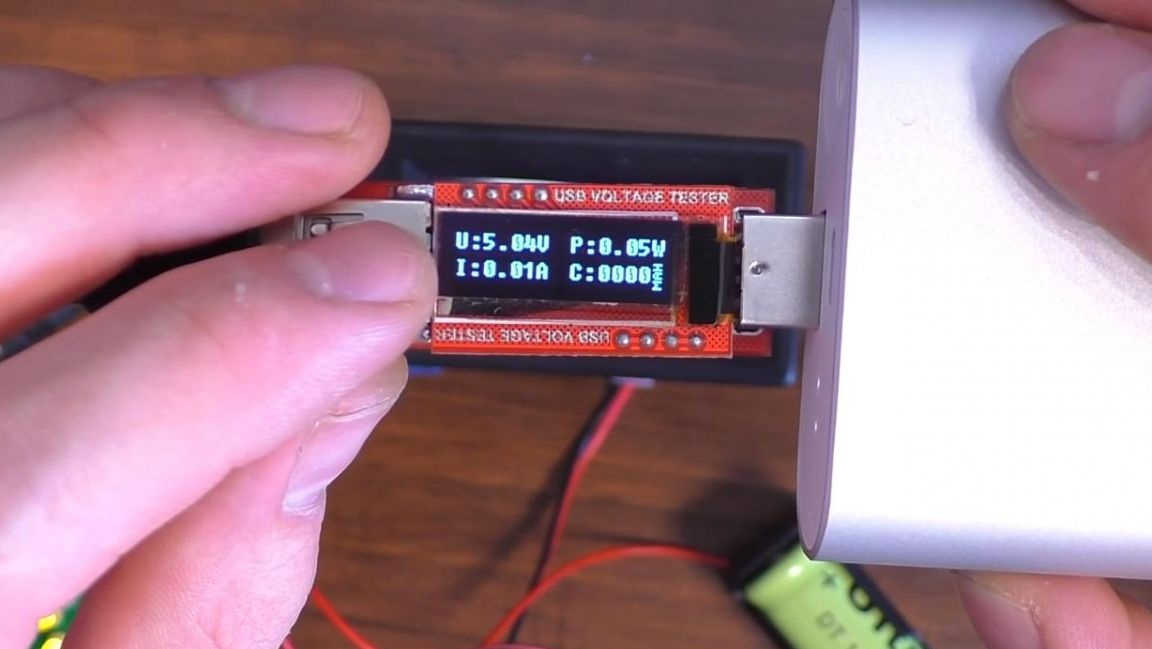
You can connect various devices to check the current consumption, in order to calibrate the measurements there is a tuning resistor. This kit kit is useful for those who want to do something. electronicwhere it is necessary to output information in real time, for example, the current consumption of an electric motor. Also, this assembly will be useful to beginner radio amateurs who want to try their hand at radio electronics.
That's all for me, thank you all for your attention and creative success.