
Hello to all lovers homemade. In this article I will tell you how to make a soldering station, the assembly of which will help the radio designer, a link to it will be at the end of the article. This kit kit will be an excellent option for continuous soldering of radio elements and will easily replace your soldering iron. The soldering station itself has a temperature control with feedback, which is very convenient, since when soldering large radio parts, the temperature on ordinary soldering irons drops and you have to wait for heating.
Before you read the article, I suggest watching a video, which shows in detail the entire assembly process of the soldering station and its small check.
To make a soldering station do it yourself, you will need:
* Kit
* Power supply with a voltage of 12-24 volts with a capacity of about 90 watts
* Soldering iron, flux, solder
* Device for soldering "third hand"
* Side cutters
Step one.
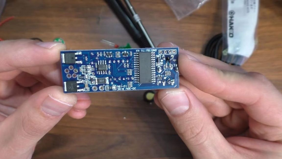
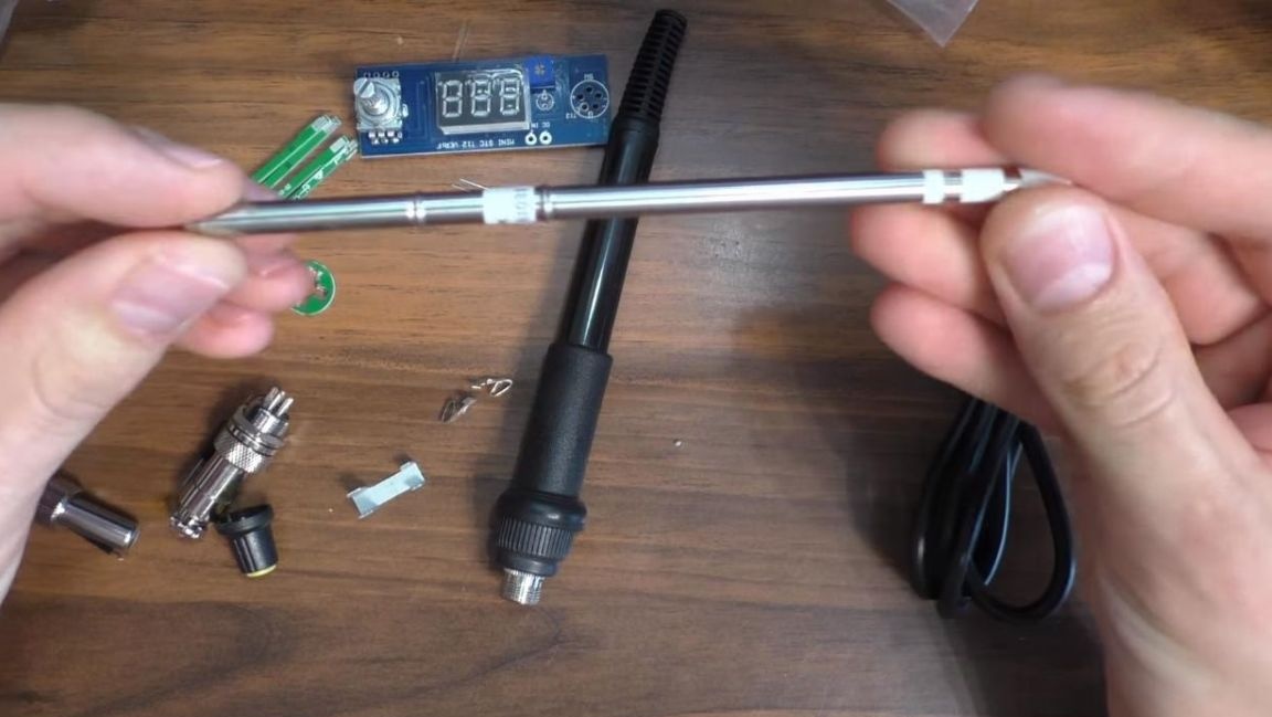
To begin, consider a set of radio constructor.
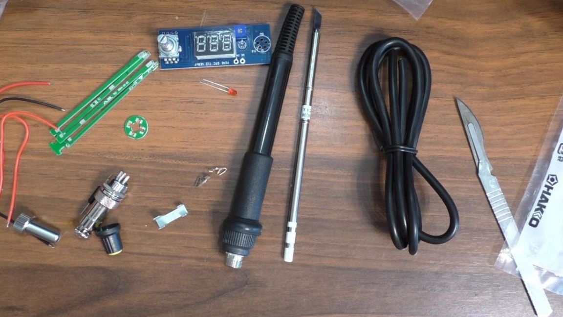
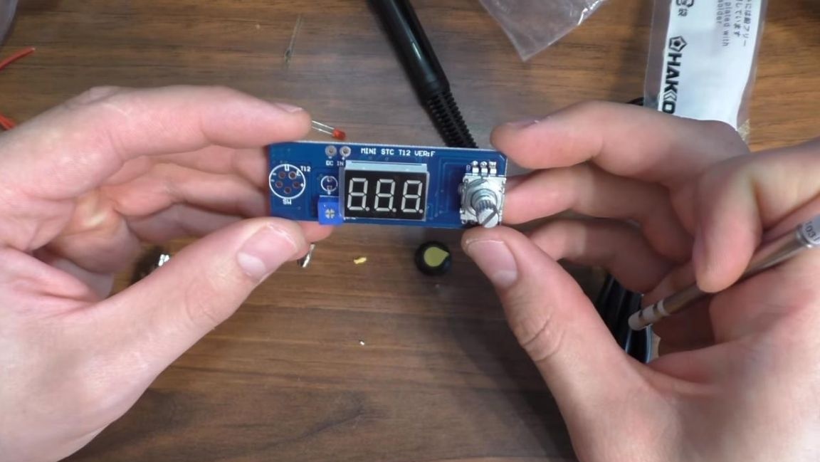
It includes a rubberized soldering iron handle, a Hakko T12 tip, a control board with an encoder for adjusting temperature and other parameters, wires for connecting power and a plug.
All parts are made with sufficient quality, the radio components are neatly soldered on the printed circuit board, there are no flux residues on its surface.
The quality of the Hakko T12 tip is excellent, it is used in many soldering stations, which means that reliability is up to standard.
We pass to assembly.
Step Two
First of all, you need to collect two parts from the PCB and fasten one round from the end. This design is needed to connect the contacts to the sting itself.
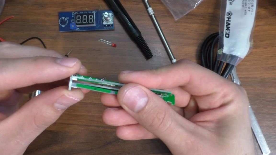
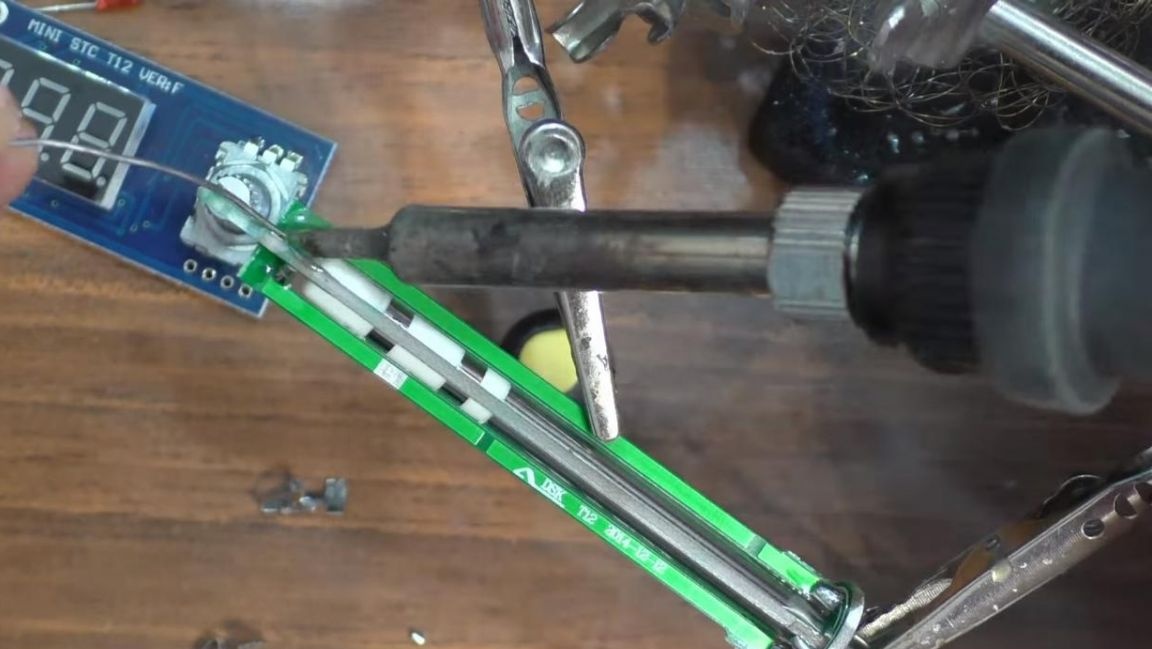
We install the parts in the third-hand soldering devices and apply flux to the contacts, after which we solder them together using a soldering iron, adding solder. We also insert a temperature sensor into special holes and solder its contacts. The excess conclusions are removed using side cutters. When removing the terminals with side cutters, be careful, as you can accidentally damage the circuit board.
Step Three
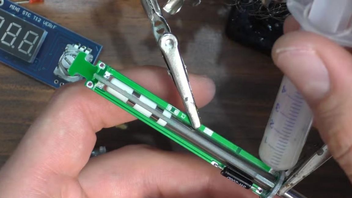
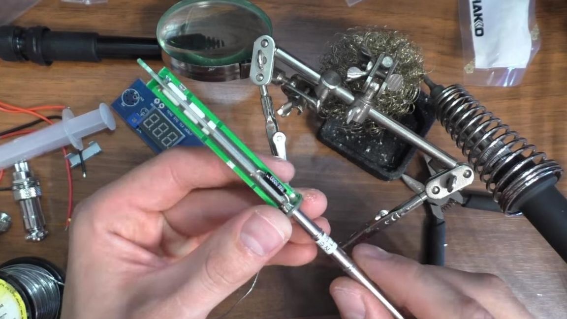
We insert the sting into the soldered part and look where it is necessary to solder the contacts for connection.
After that, we also fix the sting attachment in the soldering device and solder the contacts, there are three of them. For proper operation, the contacts must touch all three surfaces on the sting itself.
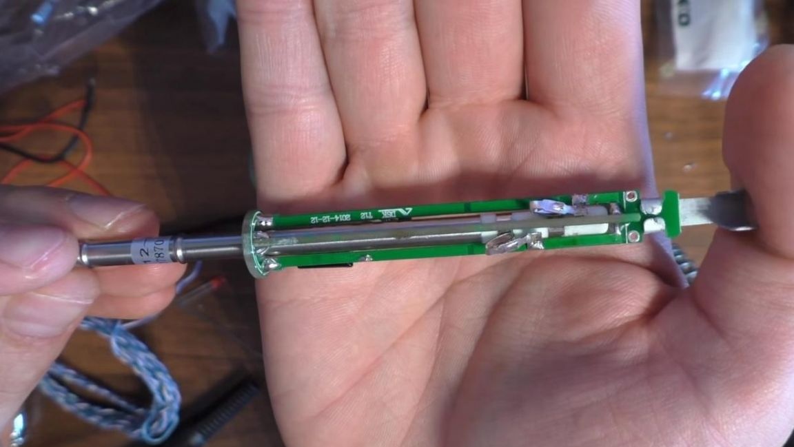
At the end of the sting mount we install a metal plate for fixing the wires.
A ceramic capacitor was not enough on one of the tracks, however, it did not go in the kit, so we solder a simple jumper from the wire vein in its place.
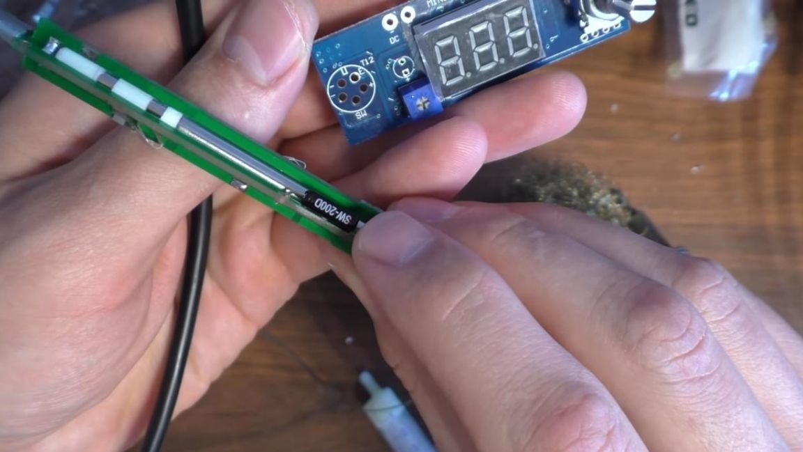
Step Four
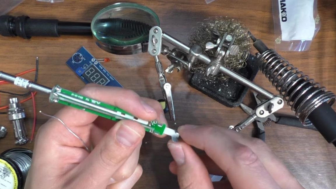
Now it's time to connect the wires to the sting attachment contacts, there are only five of them, three of them go to connect to the sting, and the other two to the temperature sensor, which will allow you to monitor the temperature. Solder the wires to the two holes and to the contacts with a soldering iron.
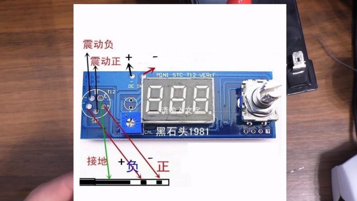
To indicate the connected power, as well as flicker when the set temperature is reached, solder the red LED, the long output is plus, short minus, the polarity on the control board is marked with a mark. Solder the wires to the plug in the picture, but before that you need to pass them into the handle.
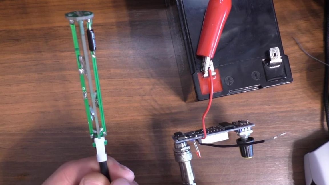
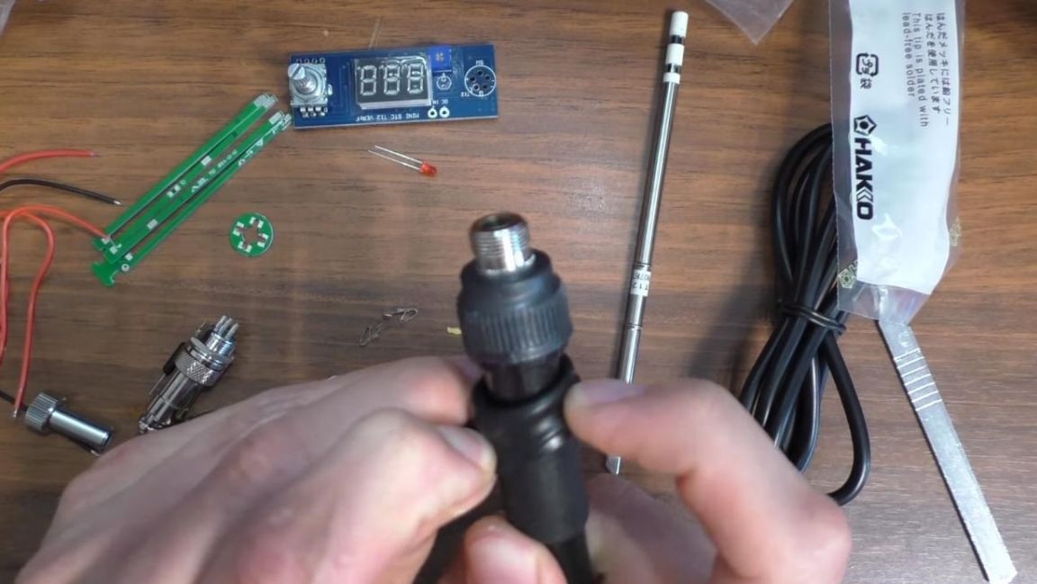
Next, we collect everything into a single whole, namely, we insert the sting into its place, then we put the metal part with a plastic nut and screw the handle onto the thread. At this stage, the assembly of the soldering station is completed, which means that the time has come to test it for operability.
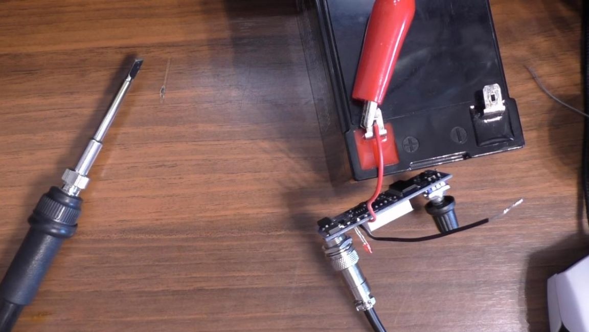
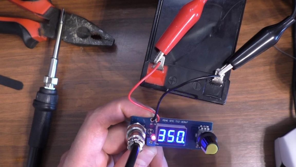
To power this soldering station, a voltage of 12 to 24 volts is required, therefore you need a good powerful power supply, you should also take into account that with a weak power supply the tip heating will not be as fast as stated by the manufacturer in the region of 10-14 seconds. We connect the power supply and set the required temperature by rotating the encoder knob in the range of 200-450 ° C, also when you click on it, you can select other parameters, for example, setting the temperature adjustment step from 1 to 9, temperature calibration and so on. The power consumption of the station is 72 watts, which is good enough for such a small soldering iron, this will allow you to heat up a large area solder without any difficulties.
That's all for me, I consider this kit to be quite suitable for reassembly, and if necessary, you can make a separate power supply in the case with a soldering iron control board.
Thank you all for your attention and creative success.