
This article will discuss how to make one simple homemade product. First, we will develop a project for it and print it on a 3d printer, and then of course we will assemble it.
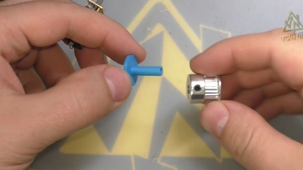
So, for starters, we design in Compass a small adapter adapter from 3 mm to 5 mm.
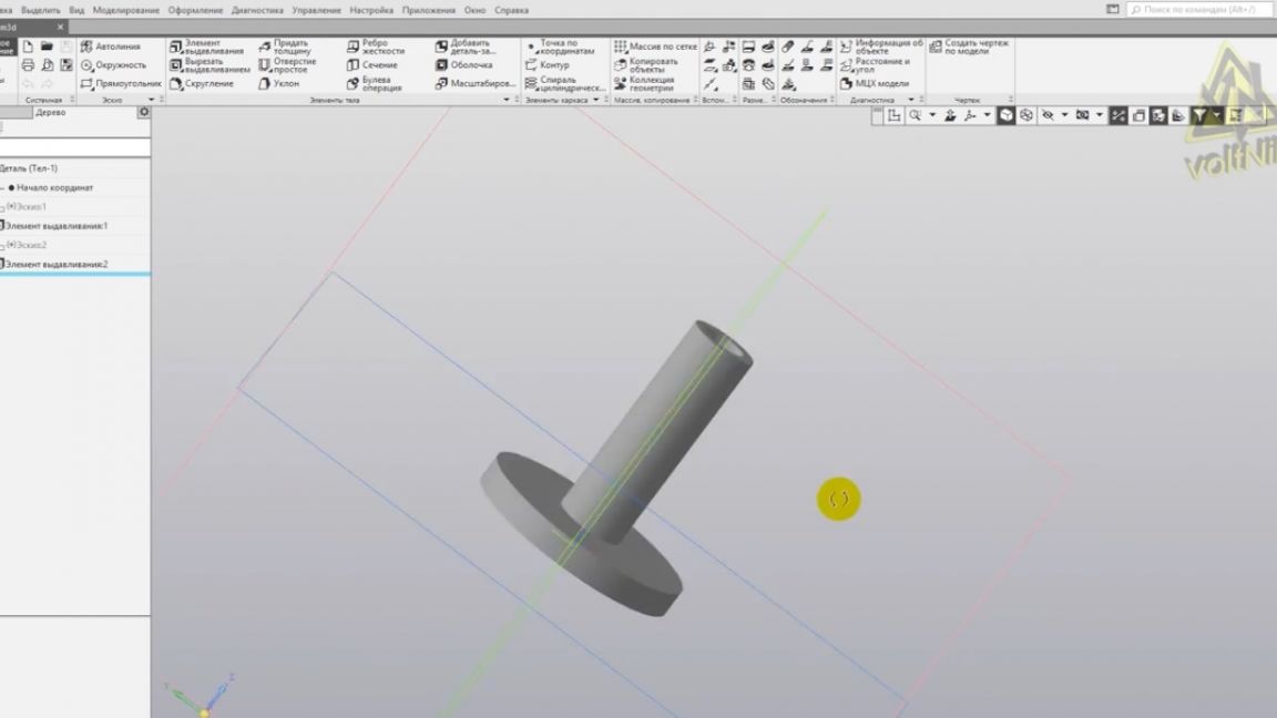
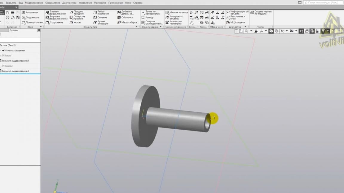
Immediately print it with a maximum accuracy of 0.1 mm.
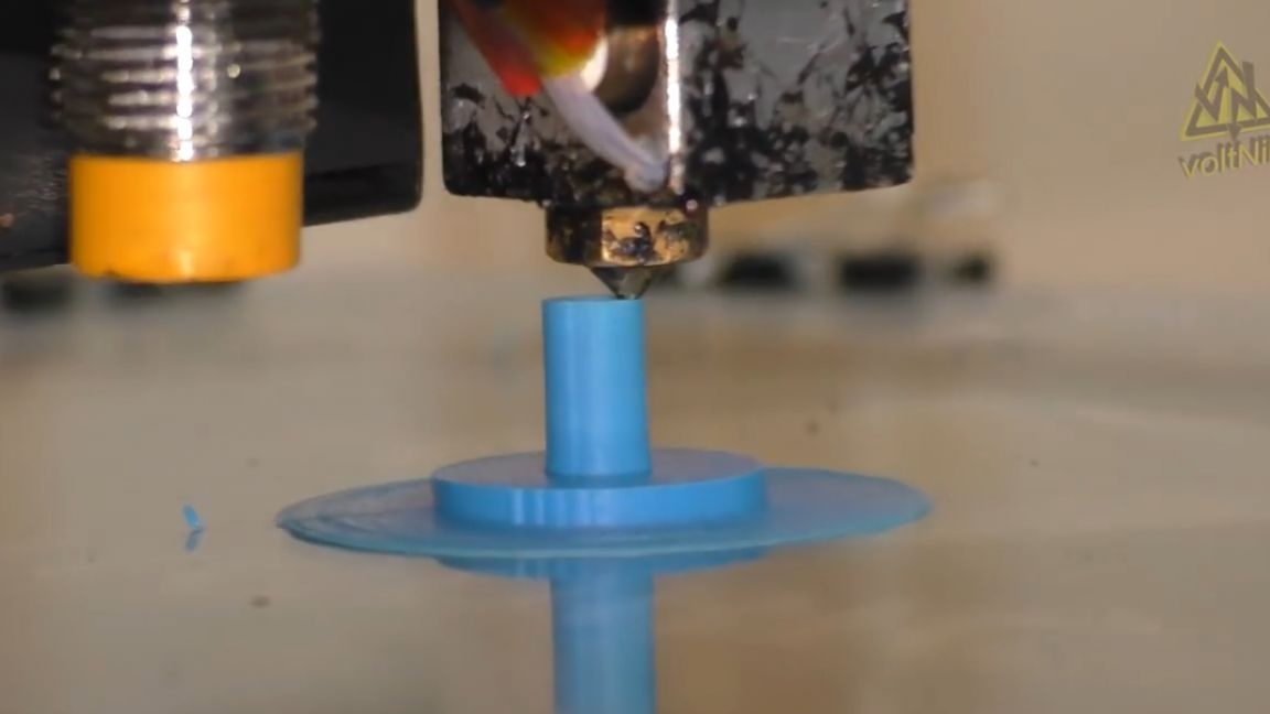
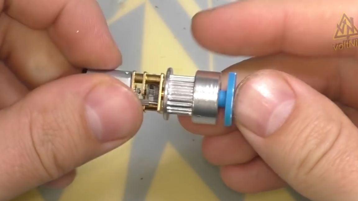
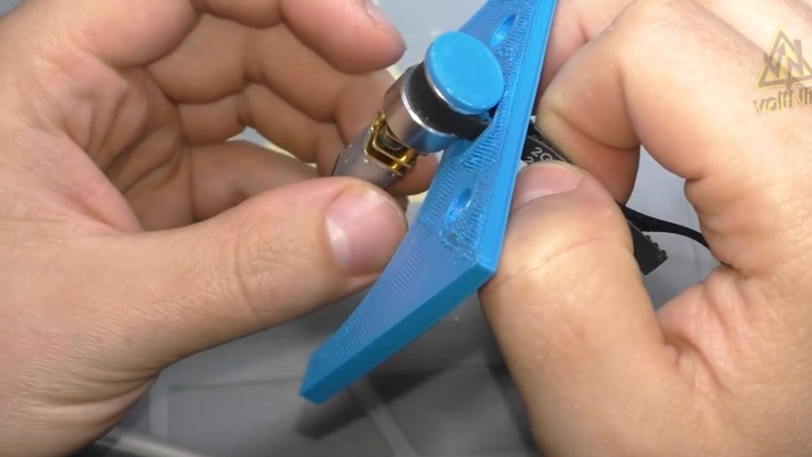
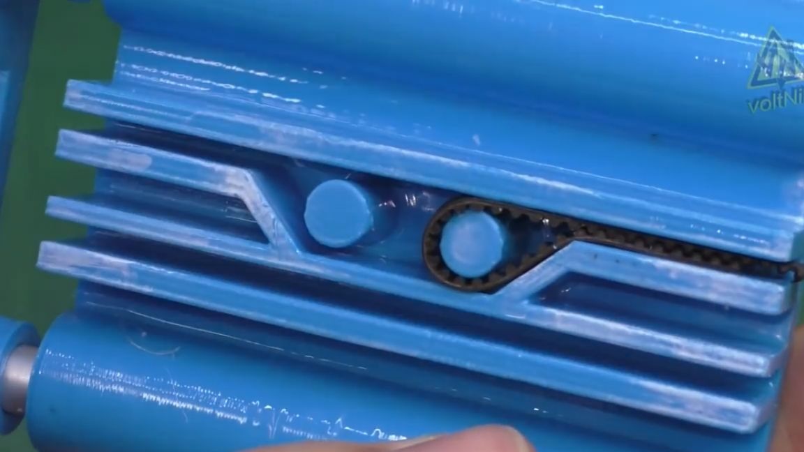
5 minutes and the sleeve is completely ready. The resulting adapter will allow you to put the gear on the micromotor.
It is still striking that it’s so easy to get almost any part, just create on a computer model and you can print it.
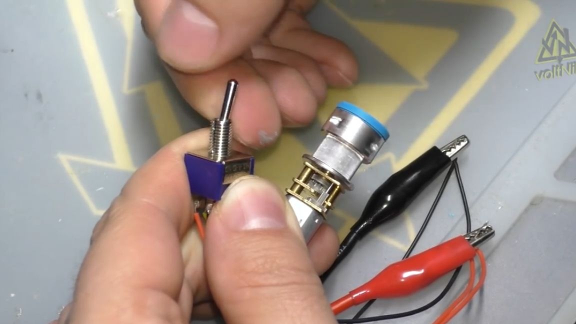
The motor shaft, of course, turned out to be a curve, but for our homemade product it’s not so critical, so we continue.
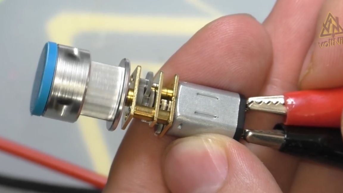
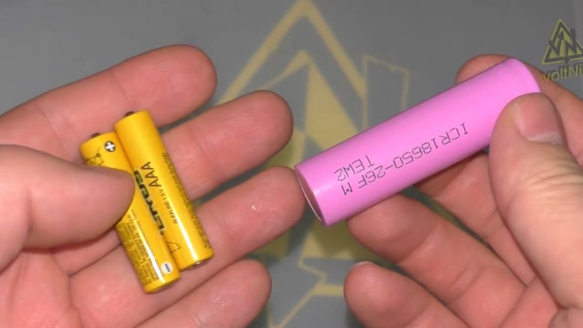
Such a motor can work from a voltage of 3 to 5 volts, that is, to power you need to use either two batteries or one can of lithium.
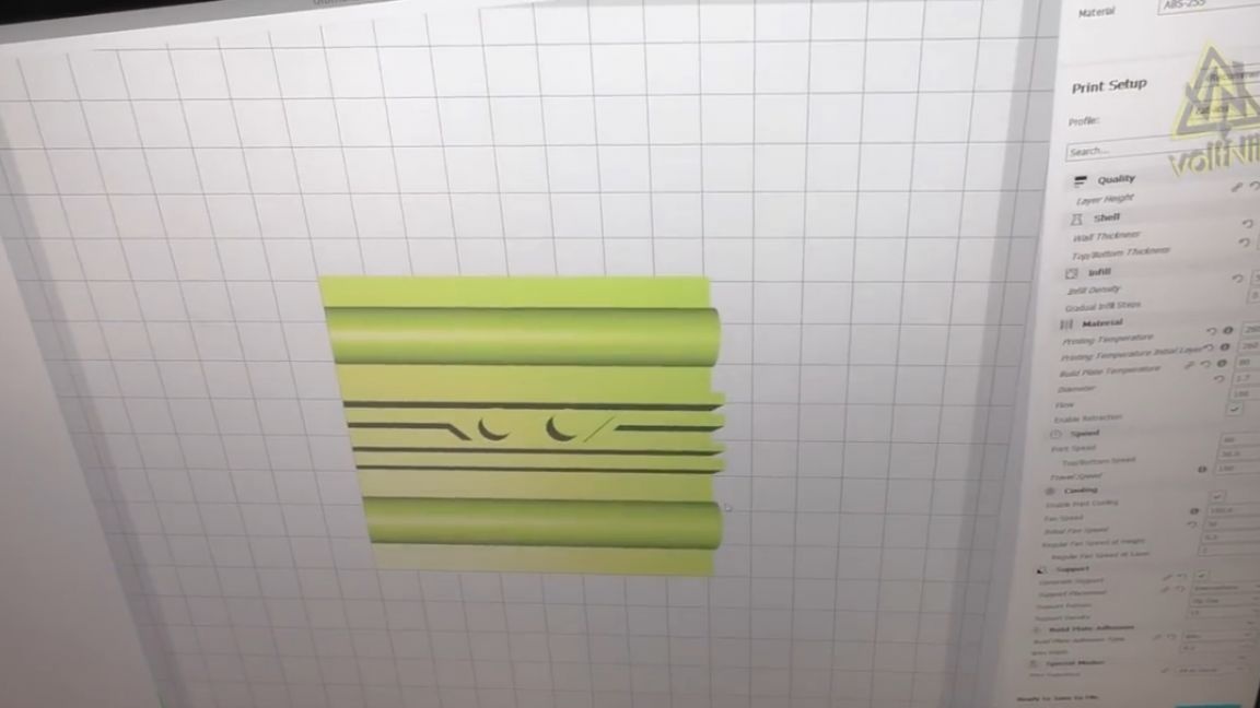
Then we prepare another draft of racks for printing. The author performs all the modeling in the new Compass 3d version 17 home. This cad has been significantly modified, it can be said that it was completely redesigned and reassembled, plus completely changed its interface. This is the first draft of the author in this program, so do not judge strictly. Simple modeling was mastered in about an hour and a half from video lessons from the world-famous and beloved Youtube video hosting. According to the author of the project, the capabilities of the Compass 3D program are absolutely identical, for example, to such programs as Solid or Inventor, and for many projects the new Compass will be more than enough.

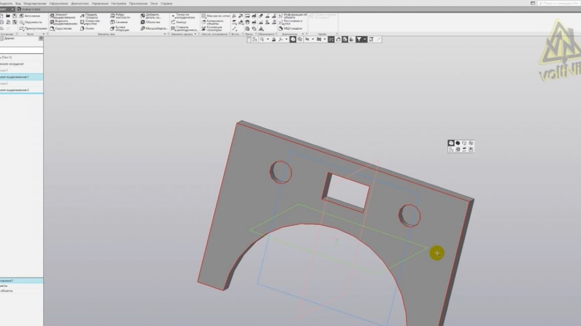
Let's continue. The rack model is ready, and now you will see how to save it in the STL file, otherwise it was redone in the new version and the author had to google it.
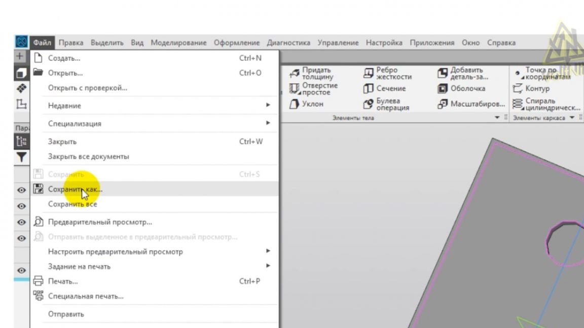
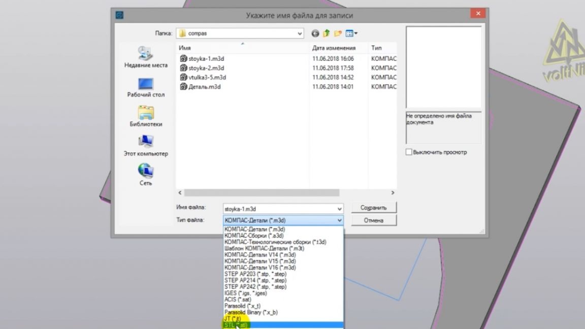
In the project, click "save as" select the format "stl" and then you must definitely click on the drop-down triangle and select "save with parameters" there.
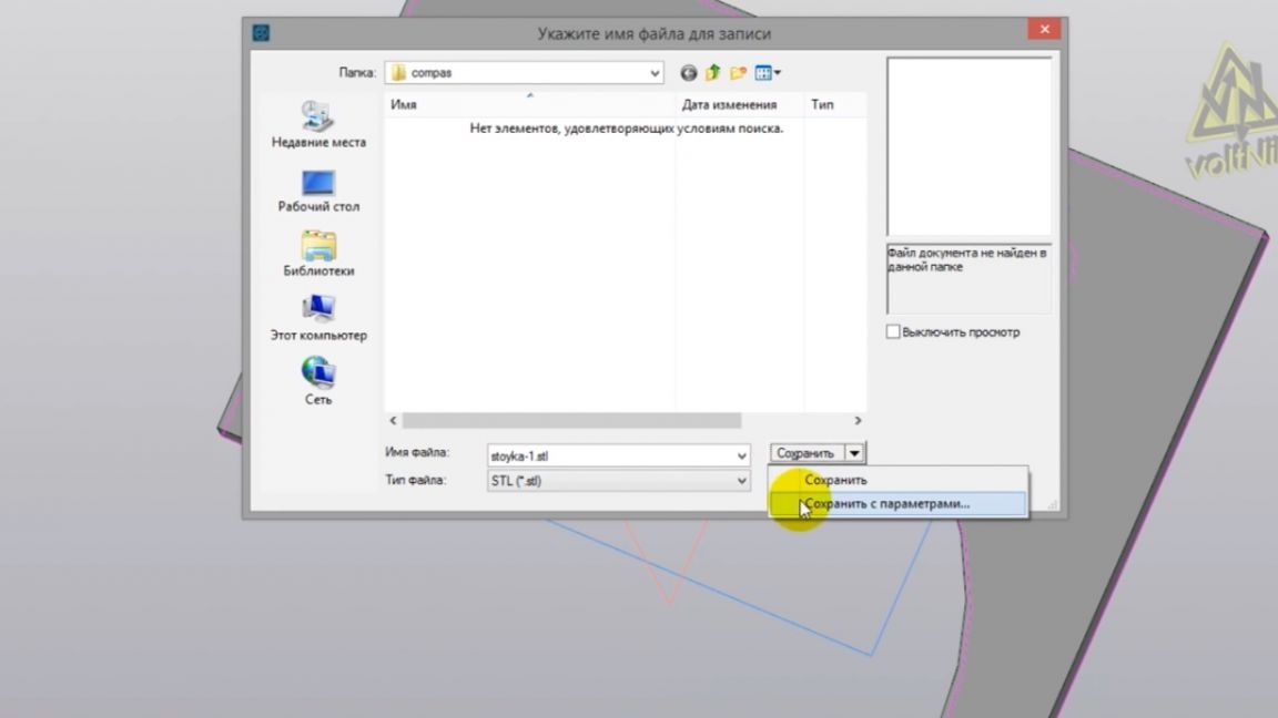
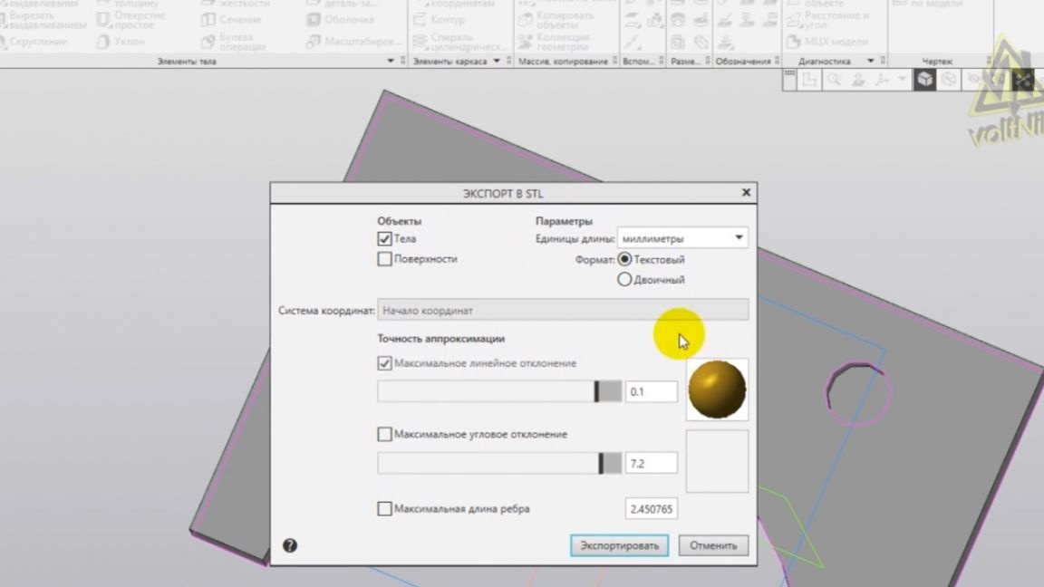
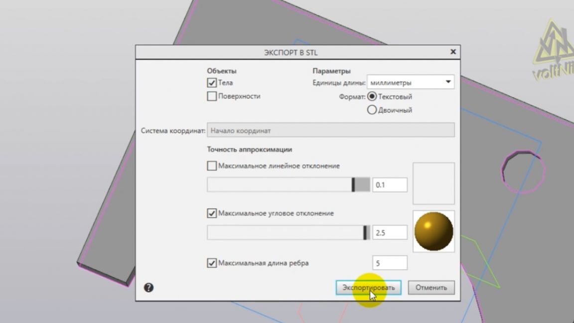
You will open an additional menu for setting and uploading to stl format. Here, in fact, the model detail is set. Compass has a whole instruction in pdf format, where unloading settings are detailed, we just set the recommended parameters and click on the “Export” button.
The file has been uploaded and now you can start the printing process. After 20 minutes of printing, we get a rack. Only now it’s impossible to fix it, and the aluminum tube does not fit into the groove.
It doesn’t matter - we redo it. And it looks like the following rack model:
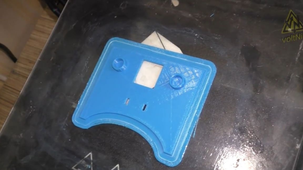
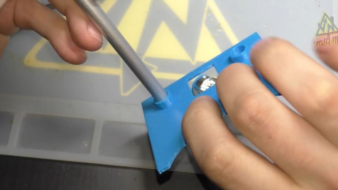
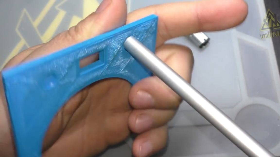
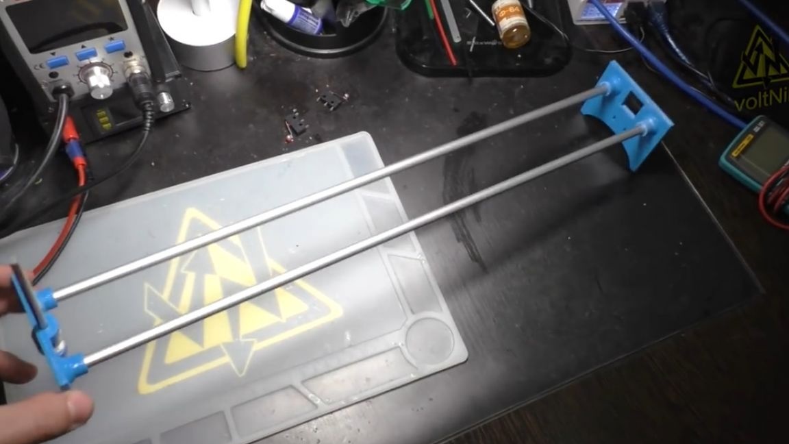
There is already a place for mounting the motor and guides. The project uses an aluminum tube with a diameter of 8 mm. We need to cut it in half, 50 cm each, a meter is a lot, half will be quite enough, so its cutter mode.
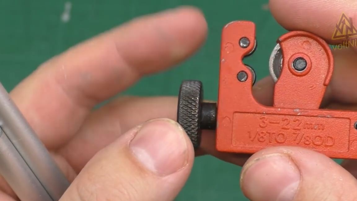
A convenient thing by the way is a pipe cutter. No need to saw anything with a hacksaw, tightened the roller, twisted it, pressed it and figax - cut.
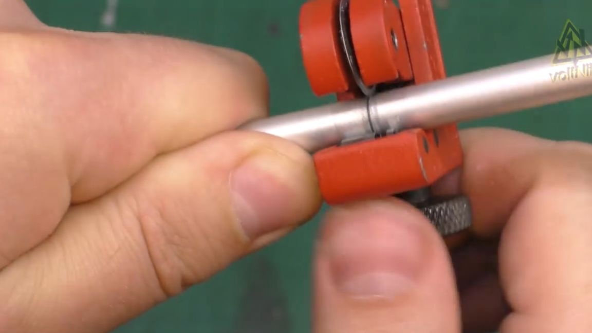
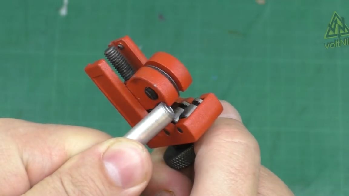
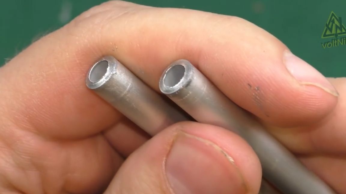
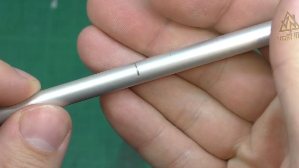
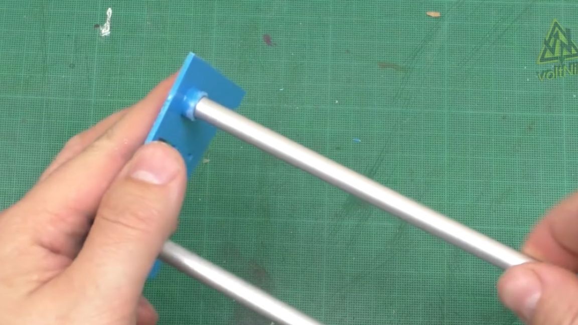
The cool thing is that the cut is accurate and even, with a hacksaw you are unlikely to succeed. Well, this is how they will be inserted there:
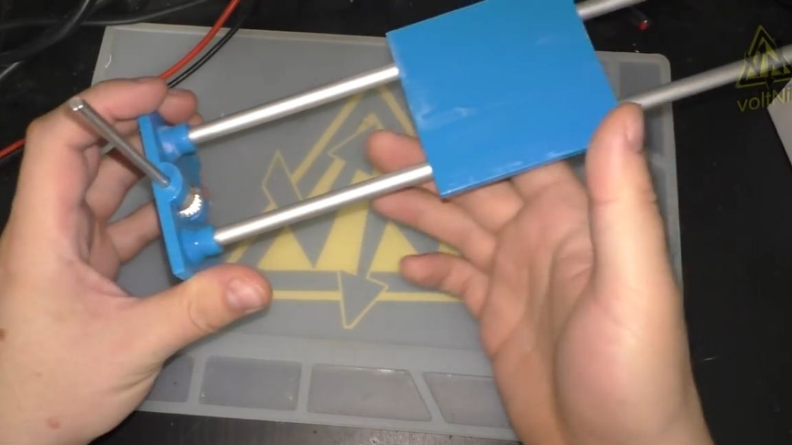
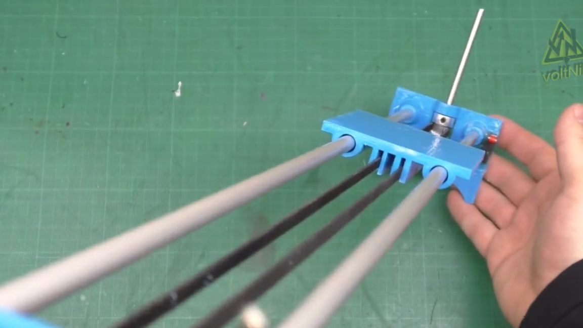
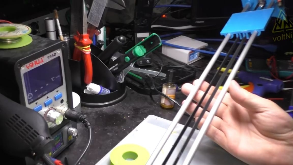
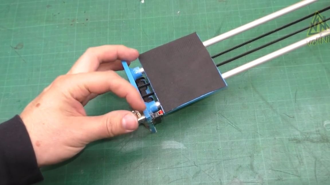
Meanwhile, a second counter was printed, and something like this would all look together:
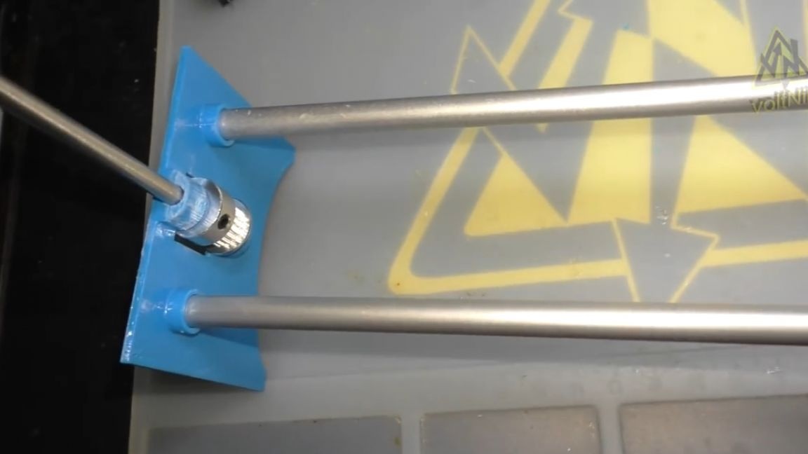
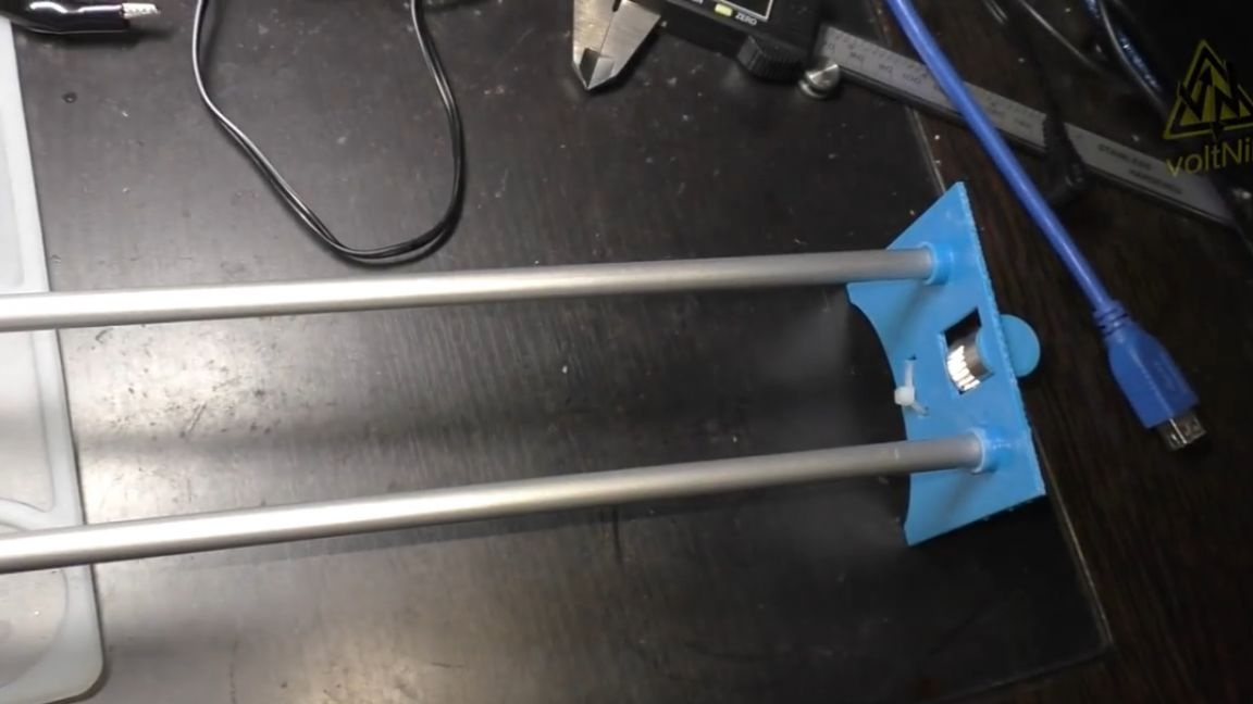
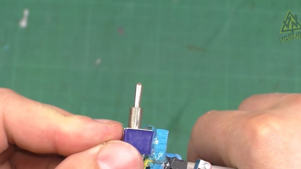
Two rails, and between them rollers with a motor. For the project, you will still need an on-off-on switch for two contact groups.
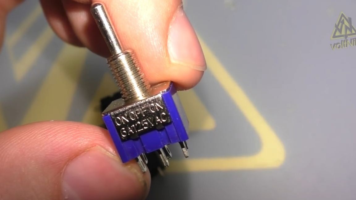
If you order them in China, then take several at once, they regularly come with marriage, then the resistance is great, then one group does not work, but it costs a lot.
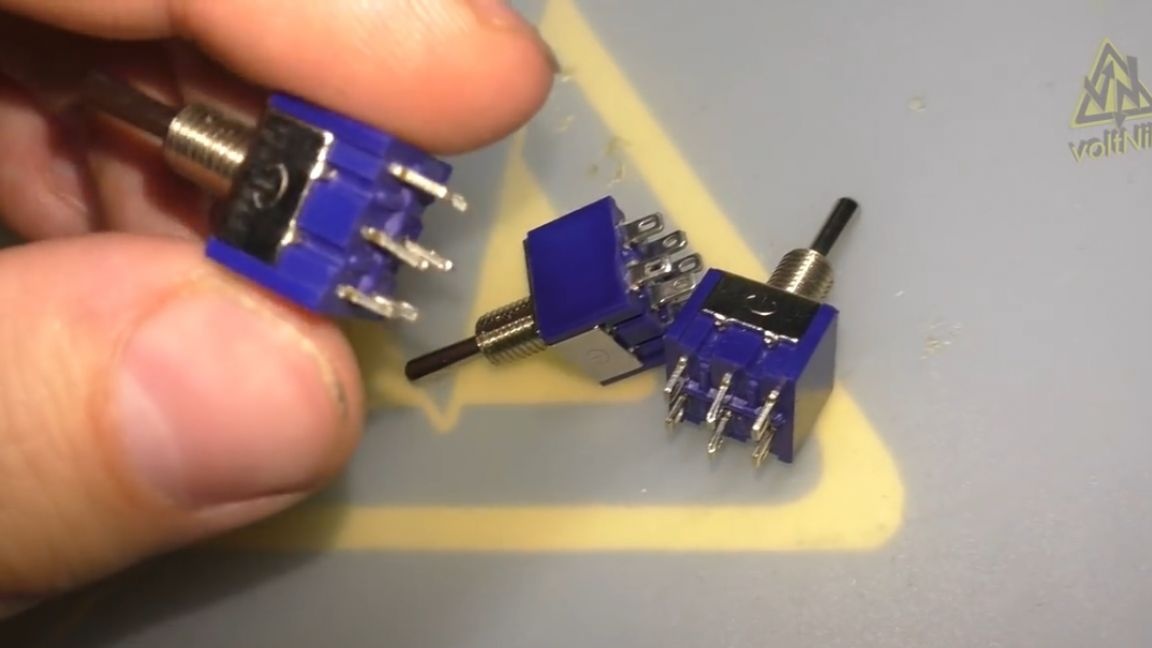
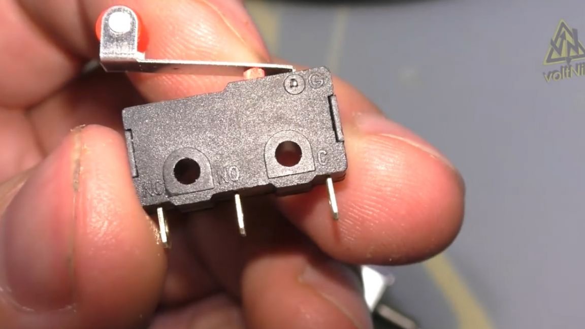
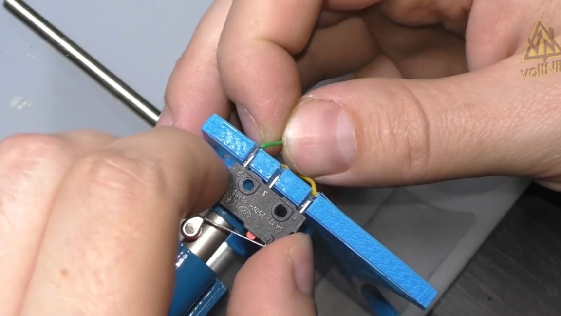
Of these three switches, only one turned out to be a worker, and two went into the trash. We also need 2 normally closed switches for limit switches.
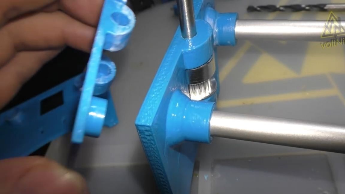
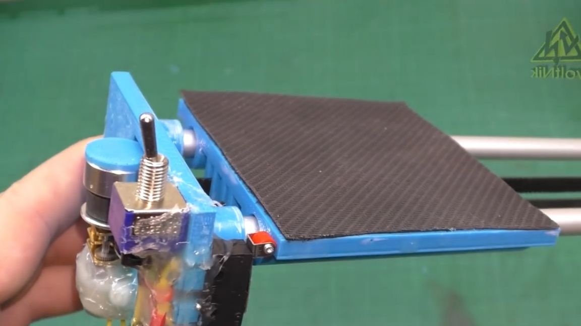
While the master assembled all this - he realized that the design was very flimsy, and printed another model of the rack. The new stand is much thicker and more massive, it also strengthened the tube holder, the new stands ceased to play, and the design became much stiffer.
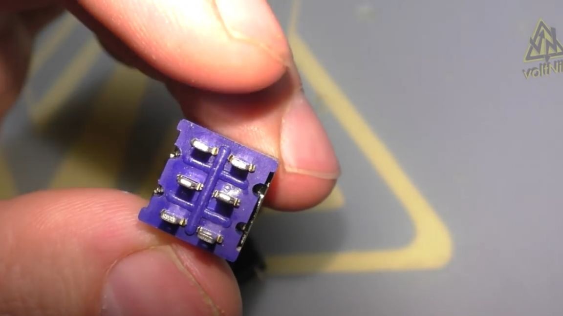
We solder the circuit breaker according to the reverse circuit: to the central contacts - wires from the motor, and to the extreme contacts plus and minus from the battery.
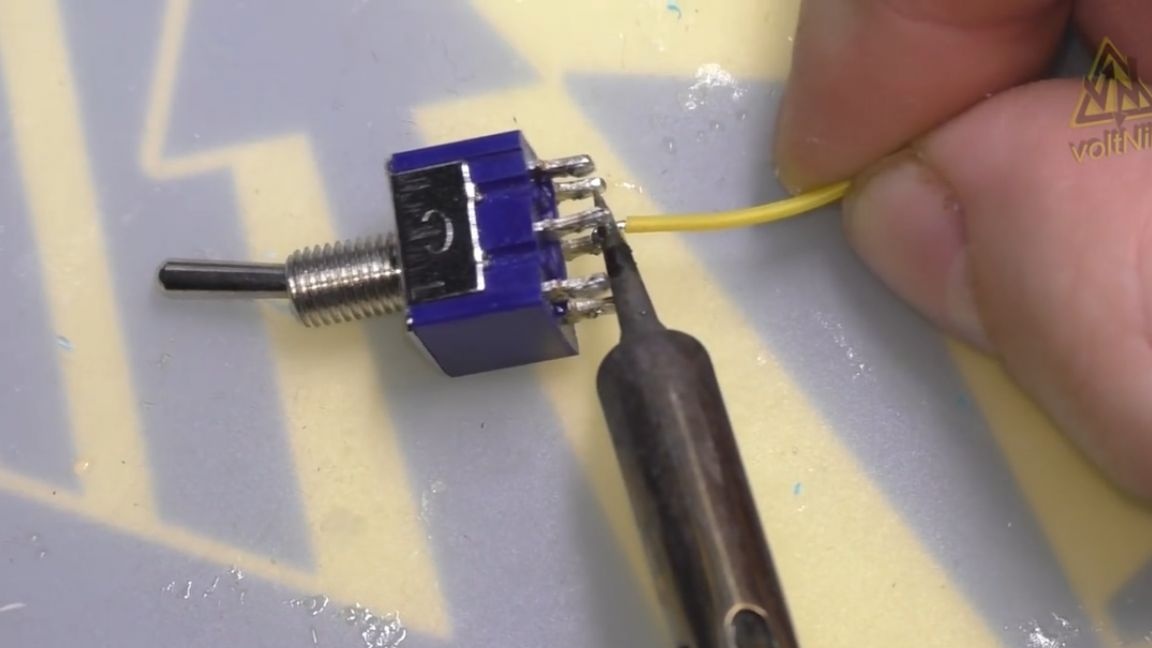
In this case, the polarity must be different on the left and on the right, this is necessary so that the switch reverses the rotation of the motor. Well, that’s what happened in the end:
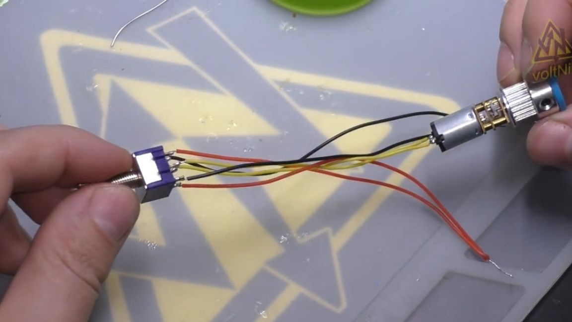
Yellow wires are the motor, black is the minus of the battery, and red is the plus. When the switch is turned on, the motor will begin to rotate in one direction, and if you switch it, it will reverse.
Well, then we are preparing a carriage project with grooves for the belt.
The first carriage, due to the large shrinkage of the blue plastic, spread along the edges and broke.
Well, nothing, we’ll print immediately the second - a modified model, it slides along the guides without any interference and difficulties.
So, the first test. The switch is a little buggy and does not always work, but the class is already working. The motor rotates in both directions and drags the carriage.
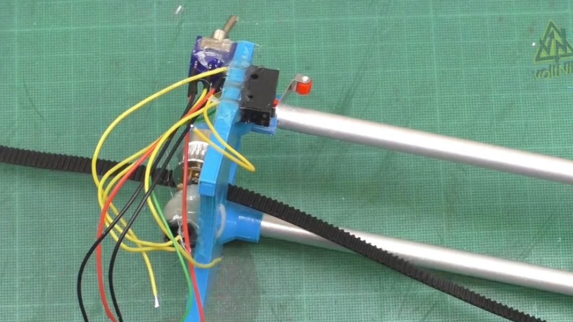
Okay, let's continue the assembly. We drill a hole in the rack, solder the wires to the trailer and thread them through the hole.
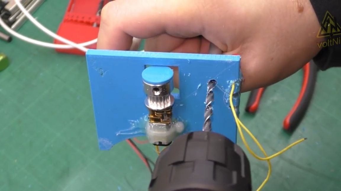
The trailer is needed in order to stop the engine when the carriage reaches the end. Of course we put it on hot glue and it will not go anywhere from here.
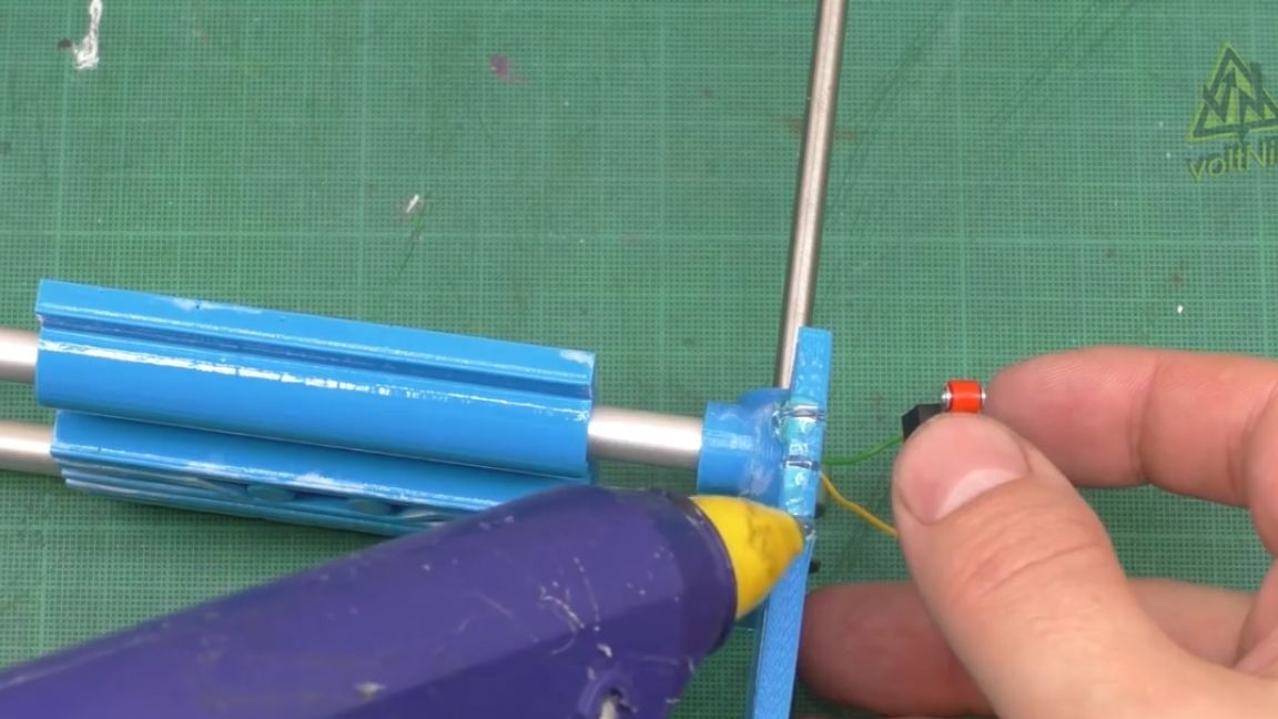
We will do the same with the switch.
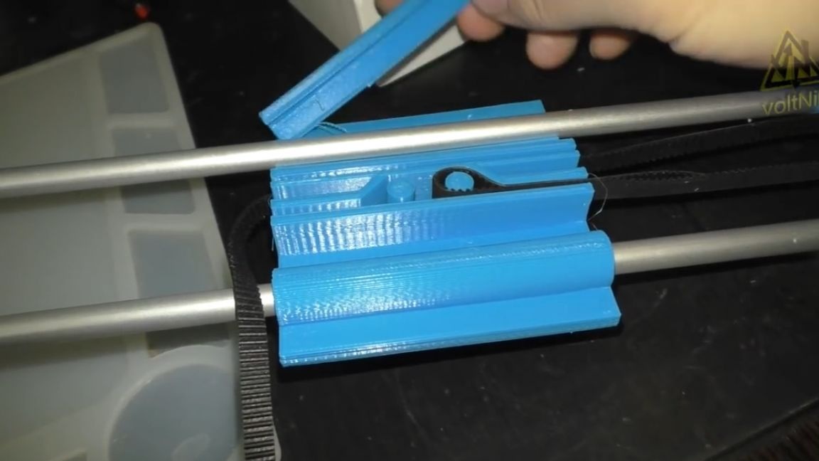
A groove for the belt is provided on the underside of the carriage.
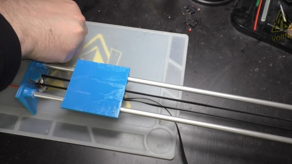
He drowns out himself and is blocked. We pass the belt through the roller and the motor, and pulling it a little, we put it on the other side of the carriage. Here's what happened at the moment:
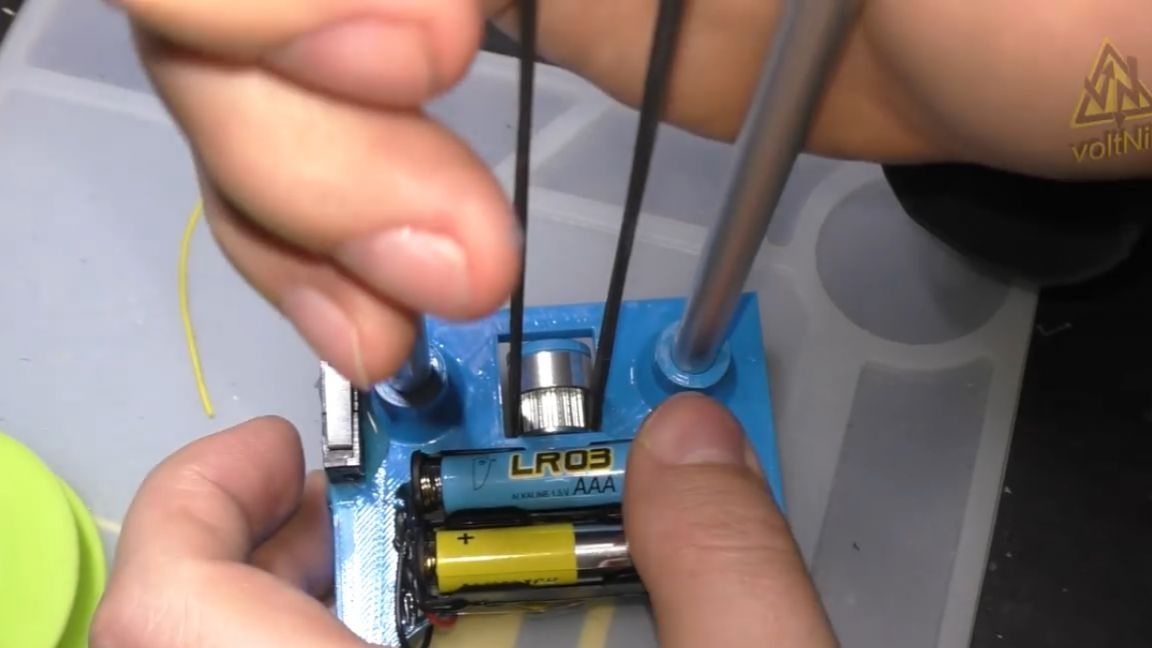
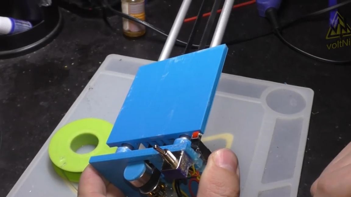
Trailers are installed on both sides, they will interrupt the circuit, stopping the motor. We will all be powered by 2 AAA batteries. We glue the case for them from below on the same hot glue, and install batteries in it.
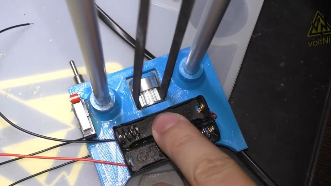
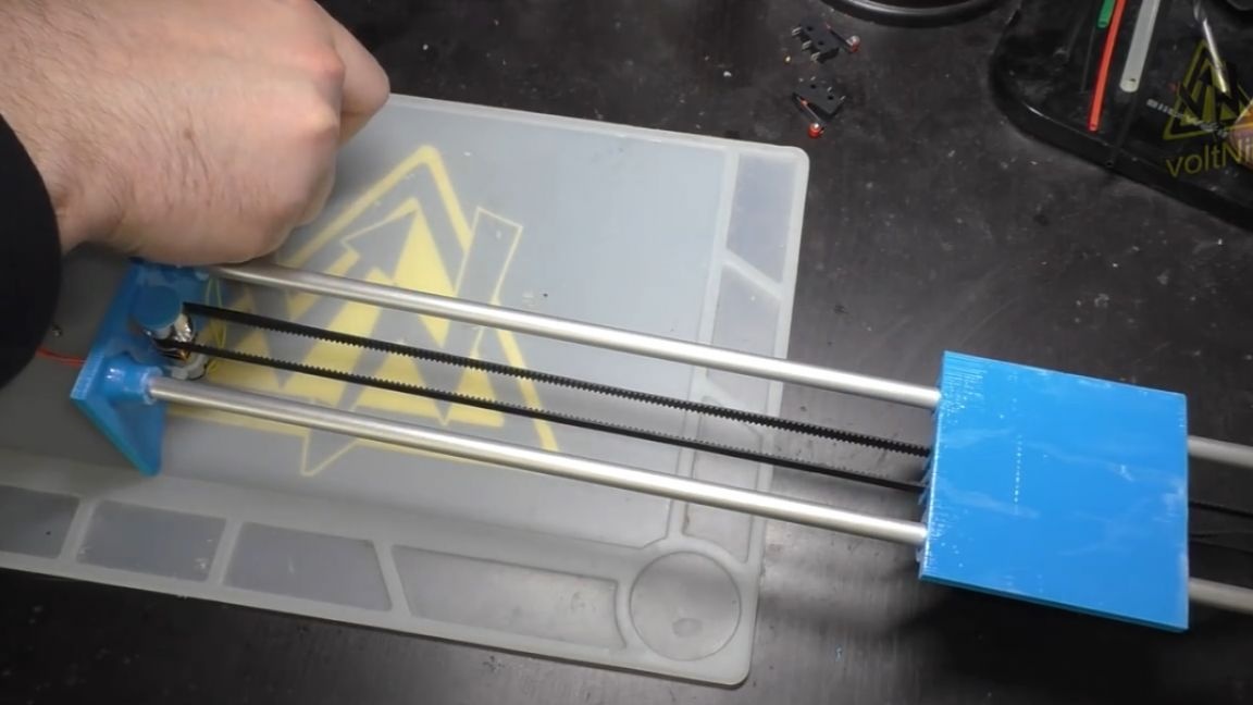
Done. When the switch is turned on, the carriage begins to move until the limit switch opens. Well, the same thing, on the other hand.
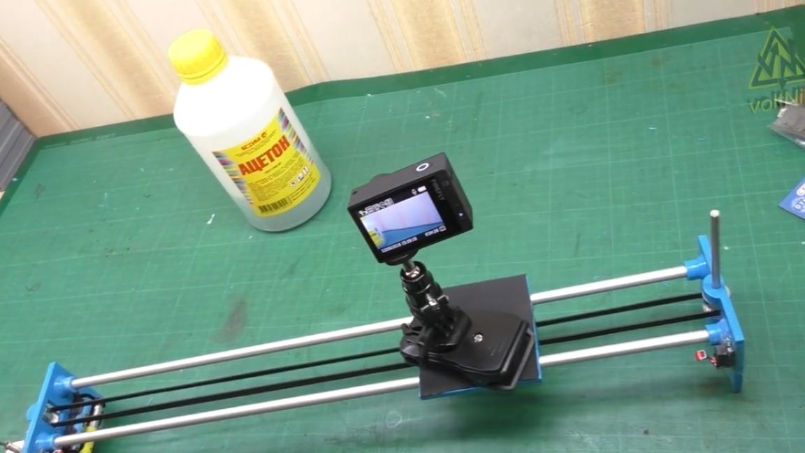
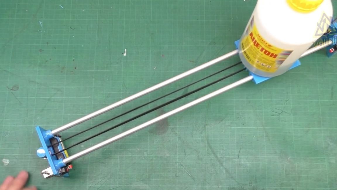
Why is all this necessary? Well, for example, you can move the bottle of acetone back and forth.
Well, of course, this project should drag the camcorder in a straight line, and then it will be the simplest slider to shoot beautiful passages over objects, but unfortunately, this motor was not very suitable for such a task, and does not provide a smooth ride, so the author more appreciates this project as a prelude to the further development of CNC machines.
Today, we essentially managed to assemble the simplest guide for moving along one coordinate axis. Thus, it is possible to realize various automatic things, such as opening and closing curtains, gates, doors, blinds and so on.And completing the project with a stepper motor and installing a microcontroller, it will be possible to indulge in automation in an adult way.
Links to all components for the assembly and files for 3d printing will be in the description under the video (for this you need to click on the link "Source" at the end of the article).
And that's all for today. Thank you for attention. See you soon!
Video: