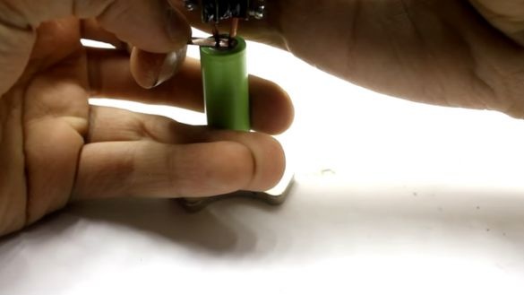
In this homemade AKA KASYAN shows the details of the manufacture of resistance welding.
Inverter type apparatus. But the device itself is very complicated (in terms of operating mode).
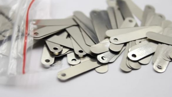
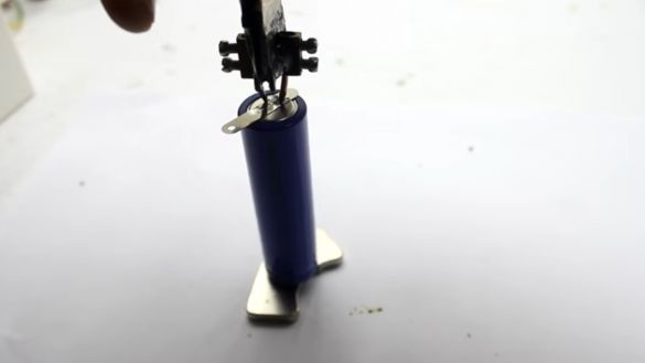
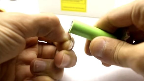
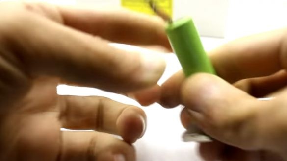
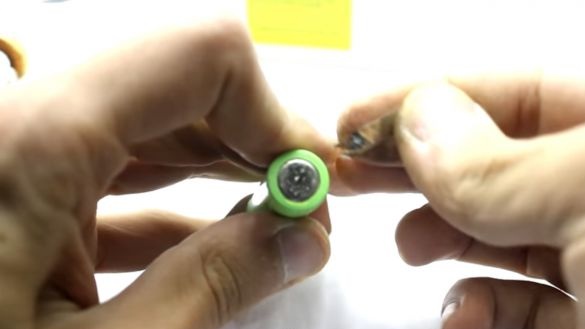
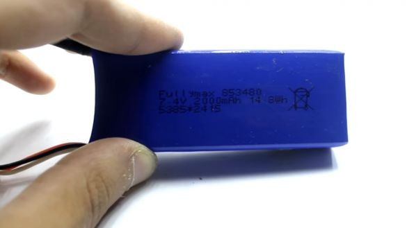
The author has a need to weld nickel plates to lithium batteries.
It was this problem that was the starter of this project.
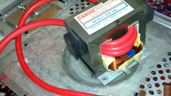
Many residents of our site are familiar with resistance welding devices, which are a bulky transformer, in the secondary winding of which several turns of a copper bus or wire are wound.
Usually they are made on the basis of a transformer from a microwave oven.
To get high welding currents of several hundred, and sometimes thousands of amperes.
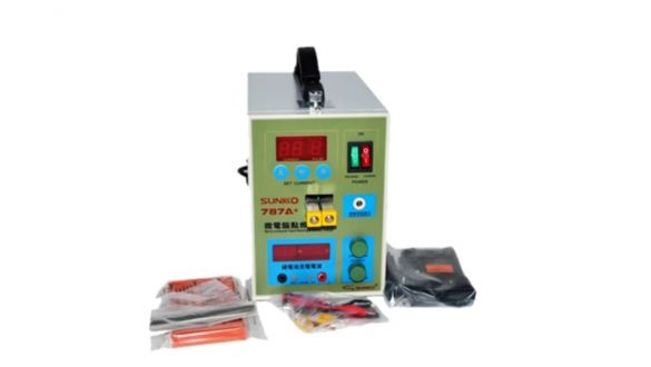
An example of a Chinese welding machine. Maximum current 500A. Buy - a couple of hundred bucks.
And here is the author’s welder, with his light weight of 200 grams, he is able to create short-time currents of 200 - 220 amperes.
The inverter mode of operation in this class of devices is a bit unusual. For resistance welding, this technology is rarely used. In his embodiment, the author uses an easy-to-implement impulse circuit.
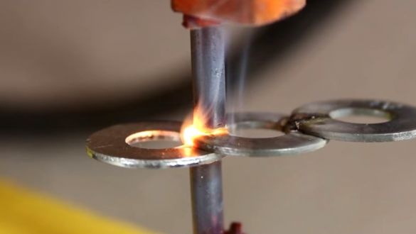
So she burns!
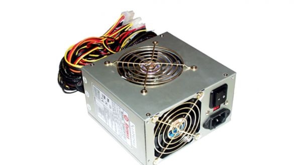
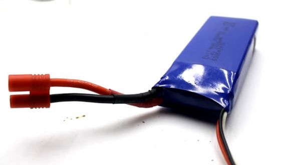
The bonus is the low-voltage power supply of the device. You can connect this unit to direct current sources (for example, a conventional computer power supply).
When using a 12V battery, autonomous and portable welding is generally obtained. The range of supply voltages is up to 24 volts.
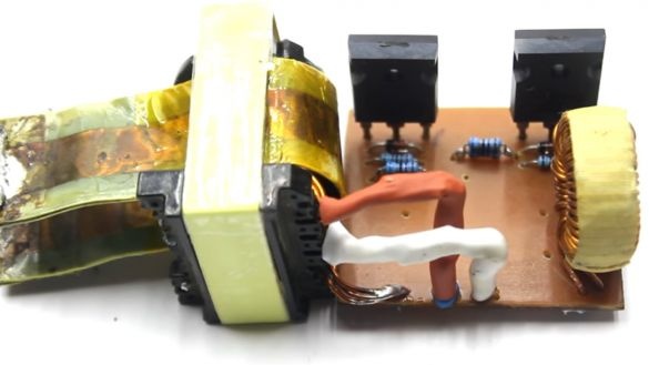
The appearance of the device at the moment is not very. He has not yet acquired a hull. (I quote the author).
The author assembled it for testing, we will not pay attention to the appearance.
If the author is satisfied with the operation of the device, then he will file several improvements, especially concerning various degrees of protection. Overheating, overexposure and in this spirit.
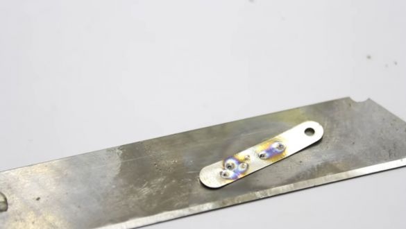
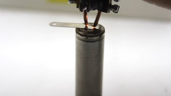
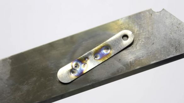
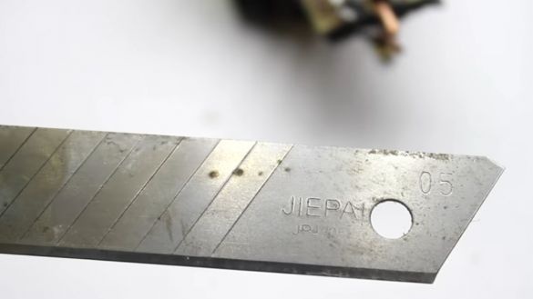
Judging by the photos - burns the blade from the knife through. So the contact of such welding is beyond doubt.
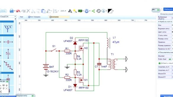
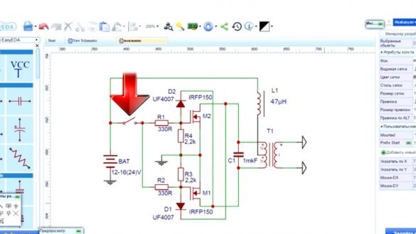
Push-pull circuitry is very popular. The auto generator, about which the author has many videos, there is no sense in explaining the principle of his work.
In the description of the video there are links to some author’s videos with various ways of applying this scheme.
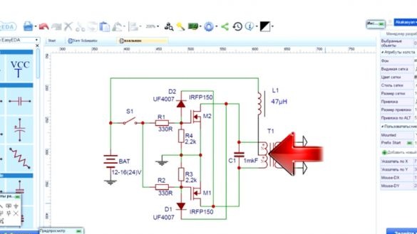
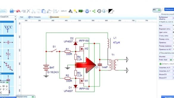
This device diagram was created using the service.
Materials and tools:
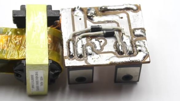
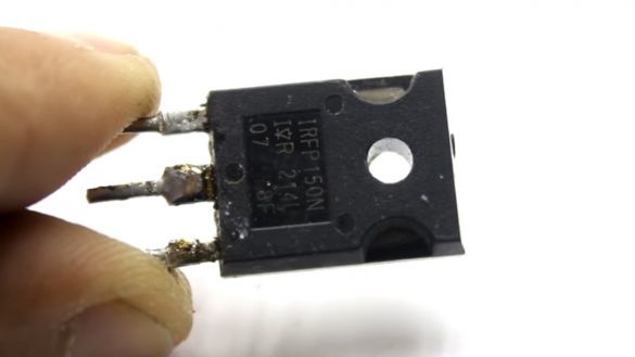
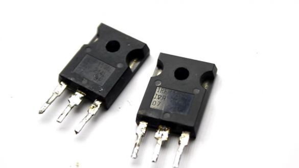
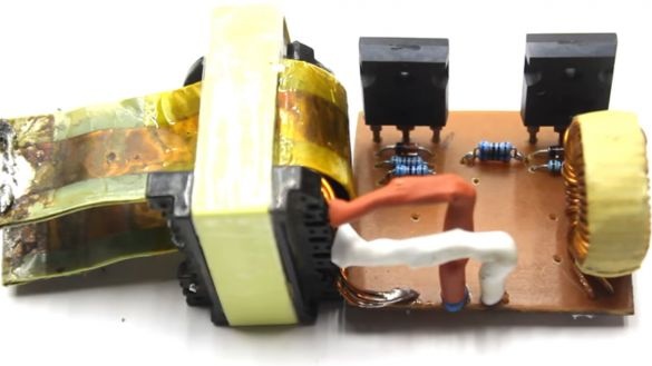
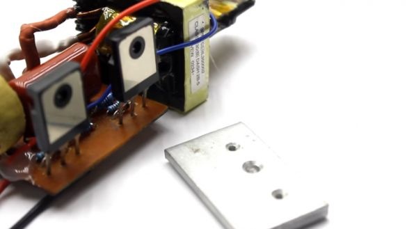
Two powerful field keys
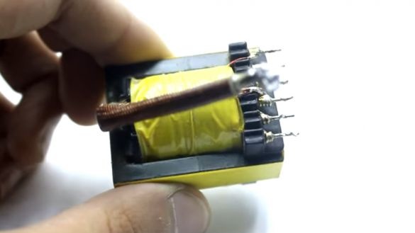
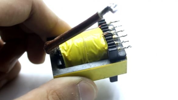
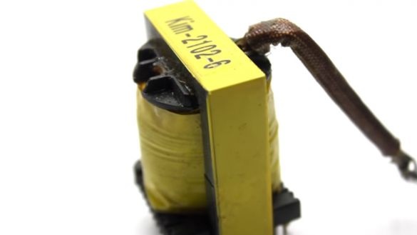
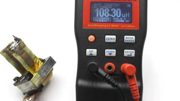
Pulse transformer from a computer power supply.
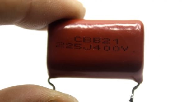
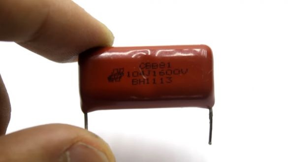
Resonant capacitor 1-2uF X 300+ Volt.
The device is turned on by a weak button.
Soldering iron, rosin, solder, textolite.
Copper wires.
Throttle.
The frequency of operation of the device depends on the inductance of the primary winding
and capacitance of the resonant capacitor.
A satisfactory frequency range is from 20 to 50 kHz. Of course, if below 20K we get into the audible frequency range.
The larger the capacitance, the higher the current in the primary winding.
The author does not recommend installing capacitors with a capacity above two microfarads.
Then the frequency of the device will fall into the audio range.
This will lead to a nasty transformer whistle.
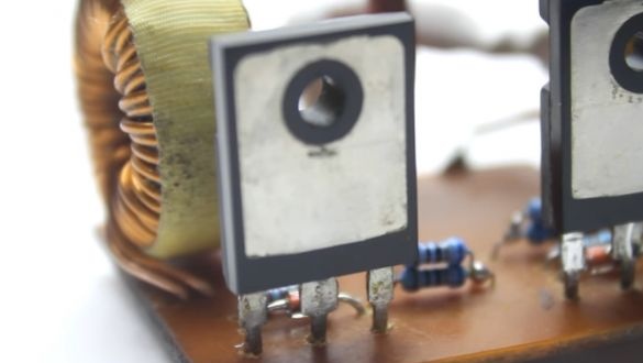
Transistors IRFP150, you can use analogues, with a current of 40A and a voltage of more than 50V.
The author recommends the use of keys in the TO247 case. You can and TO220.
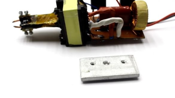
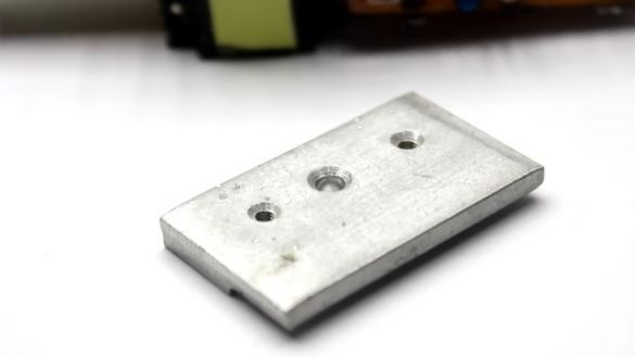
We attach a small radiator to the transistors. In the form of a plate.
The keys themselves must be isolated from the radiator.
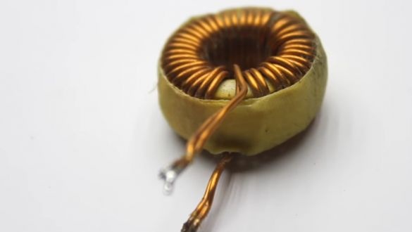
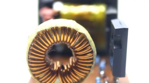
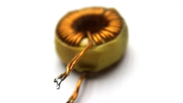
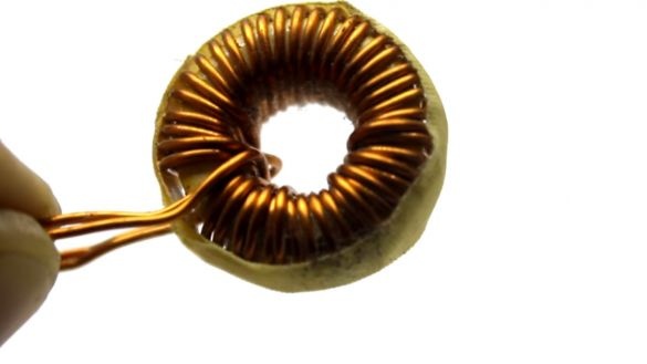
A throttle is a must. It is wound in two one and a half millimeter veins.
The number of turns in the range from 10 to 30 pieces.
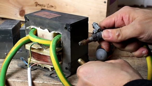
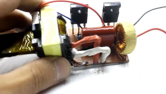
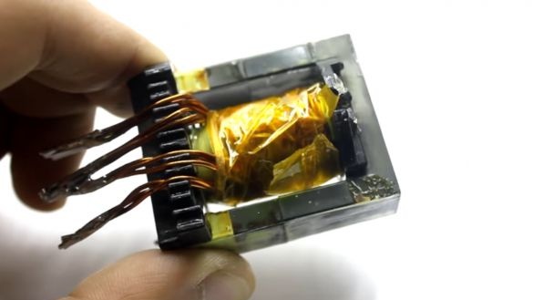
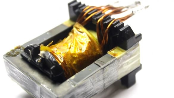
Power pulse transformer confiscated from a classic ATX 450W computer power supply.
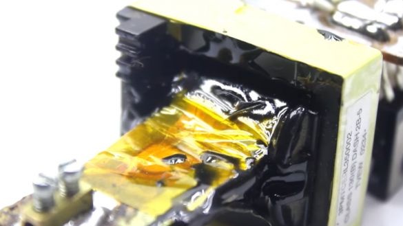
We remove factory windings. To do this, I recommend heating it with a building hairdryer.
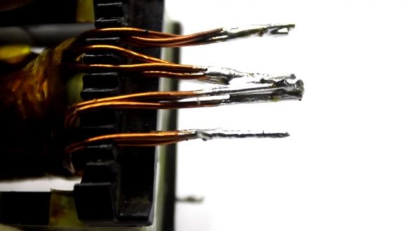
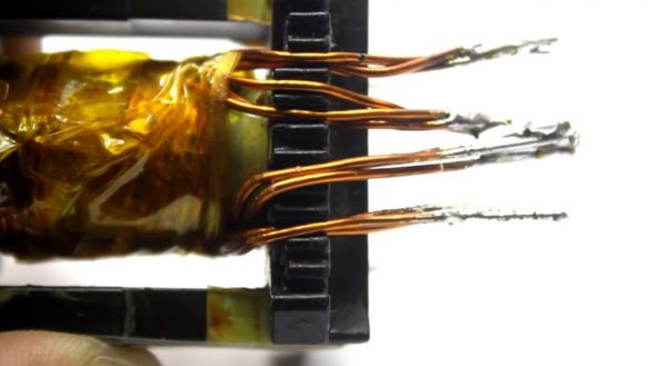
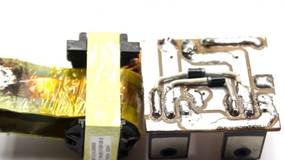
So, the rewound primary consists of two loops of four turns each.
Wound with a 3-wire bundle with a diameter of 1 mm.
The total quadrature of the primary should be 2-4 squares. In principle, it is possible to wind from a stranded wire.
Insulates the winding with heat-resistant adhesive tape on top. I would make lavsan.
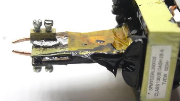
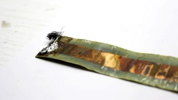
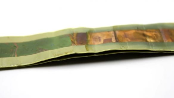
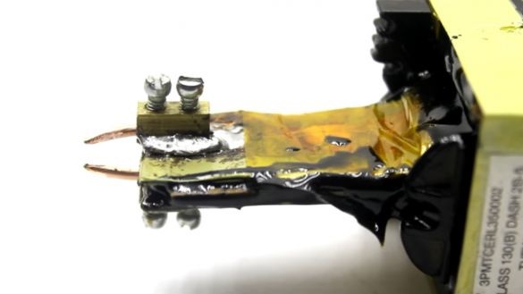
The secondary loop is made of a copper bus 1.5mm X 22mm
The copper tape is fixed with epoxy.
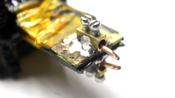
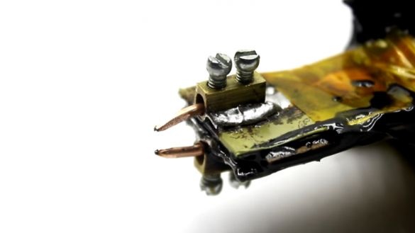
And to the ends of the winding solder the terminals,
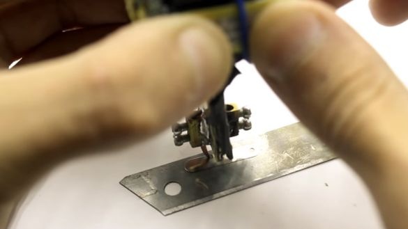
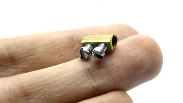
Actually, single-core 2 mm copper electrodes are inserted into the terminals
The edges of the electrodes must be sharpened.
Yes, a few innovations, instead of copyright copper electrodes, graphite can be used. You can make them from a construction pencil.
The case for the author is not important yet. After testing the device, the case will be made of plexiglass or textolite.
Let's see what the unit is capable of.
Yeah, it’s impossible to tear.
Is that the tape is torn.
The supply voltage is from six to 24 V. And this is autonomy in the presence of a high-quality battery with a large output current.
Yes, at least from a screwdriver, the battery can be prikolkhoz.
A question that arises for most readers. Why is the circuit required, and why can’t it be cooked directly from the battery? The author’s answer is that the circuit lowers the voltage to 1.5 - 4V. Naturally, the welding current increases. And the battery when working on a short circuit - almost immediately turns into junk. Actually, this is not safe.
The author's version is suitable for all characteristics.
Recently, the author made a similar welding machine based on capacitors.
Modes of operation of the device. For one welding - up to two seconds, after - a break of 4 seconds.
The author burned several field workers. Just cooked for 5 seconds. And the transistors were without a cooling radiator.
Thanks to AKA KASYAN for the work done!
Good luck to everyone and good ideas!
Link to the original video - under the text is the "source" button.

