
Greetings the inhabitants of our site!
Today we will assemble a powerful laboratory power supply. At the moment, it is one of the most powerful on YouTube.
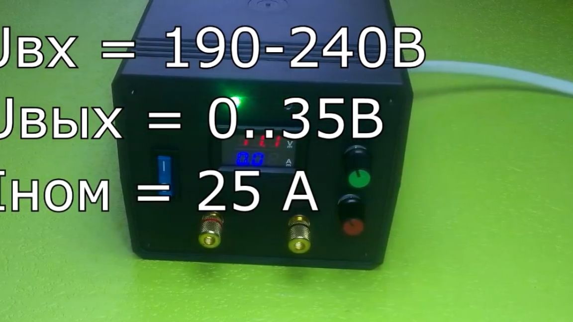
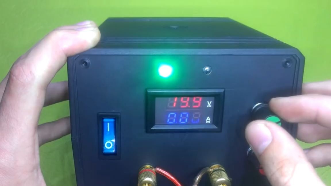
It all started with the construction of a hydrogen generator. To feed the plates, the author needed a powerful power supply. Buying a finished unit like DPS5020 is not our case, and the budget did not allow it. After some time, the circuit was found. Later it turned out that this power supply is so versatile that it can be used absolutely everywhere: in electroplating, electrolysis and just for powering various circuits. Immediately go over the parameters. The input voltage is from 190 to 240 volts, the output voltage is adjustable from 0 to 35 V. The output rated current is 25A, peak - over 30A. Also, the unit has automatic active cooling in the form of a cooler and current limits, it is also protected against short circuit.
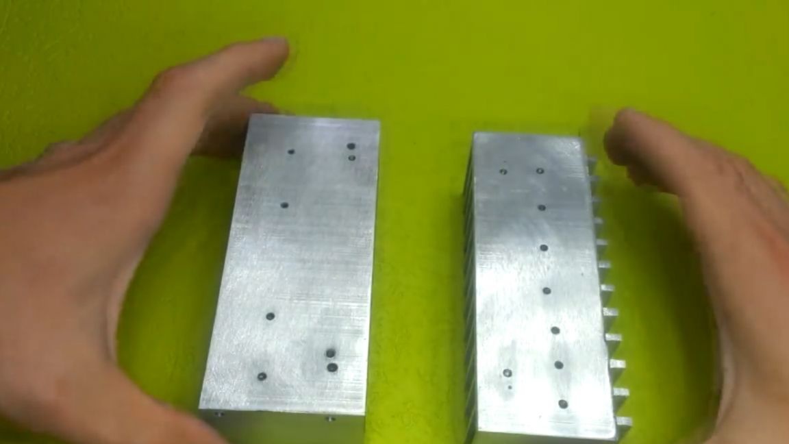
Now, as for the device itself. In the photo you can see the power elements.

One look at them is breathtaking, but I would like to start my story not at all with the diagrams, but directly from what I had to start from, making this or that decision. So, first of all, the design is limited by the body. This was a very big obstacle in the construction of printed circuit boards and the placement of components. The case was bought the largest, but still its dimensions for such an amount of electronics are small. The second obstacle is the size of the radiator. It is good that they were found in accuracy, suitable for the case.
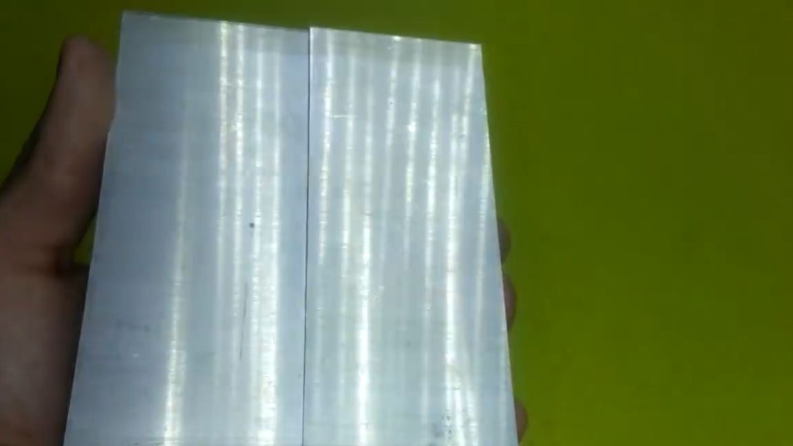
As you can see, there are two radiators, but we will combine the construction in one. In addition to the radiator, a power transformer, a shunt and high-voltage capacitors must be installed in the case. They did not interfere with the board, they had to be taken out of bounds. The shunt is small, it can be put to the bottom. The power transformer was only available in these sizes:

The rest were sold out. Its overall power is 3 kW. This is of course much more than necessary. Now we can proceed to consider schemes and seals. First of all, we will consider a block diagram of the device, so it will be easier to navigate.
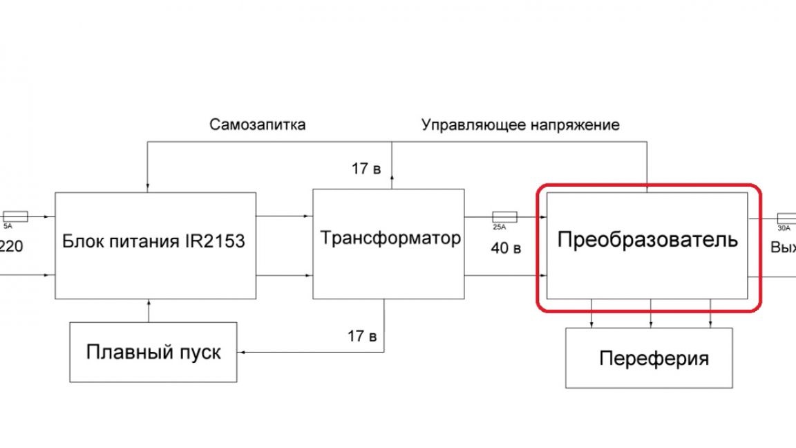
It consists of a power supply, dc-dc converter, soft starter and various peripherals. All units are independent of each other, for example, instead of a power supply, you can order a ready-made one. But we will consider the option of how to do everything do it yourself, and it’s up to you to decide what to buy and what to do as well.It is worth noting that it is necessary to install fuses between the power units, since if one element fails, he will drag the rest of the circuit to the grave, and this will fly you a pretty penny.
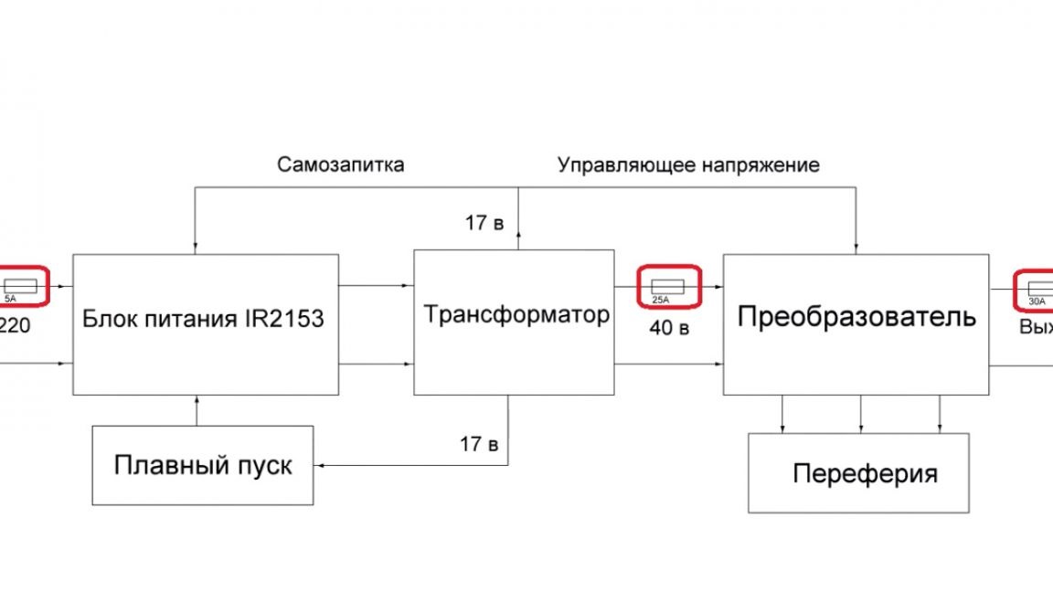
Fuses on 25 and 30A just right, as this is the rated current, and they can withstand a couple of amperes more.
Now, in order about each block. The power supply is built on the beloved ir2153.
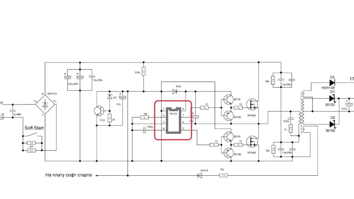
Also added to the circuit is a sophisticated voltage regulator to power the microcircuit. It is powered from the secondary winding of the transformer; we will consider the parameters of the windings during winding. Everything else is a standard power supply circuit.
The next element in the circuit is a soft start.
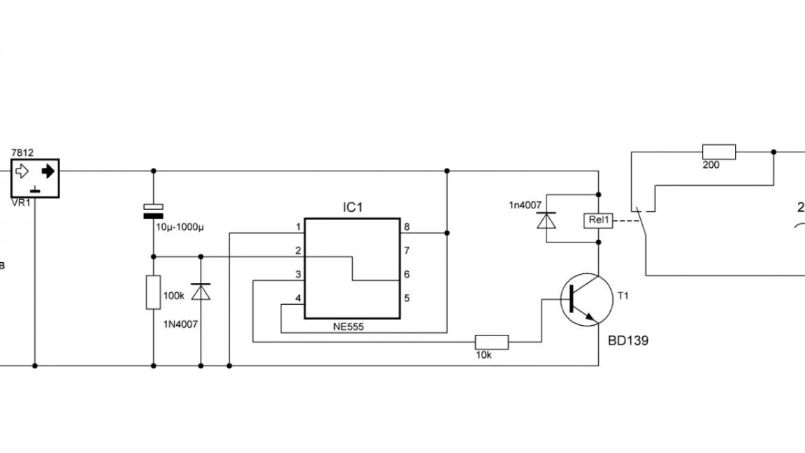
It is necessary to install it to limit the charging current of the capacitors, so as not to burn the diode bridge.
Now the most important part of the block is the dc-dc converter.
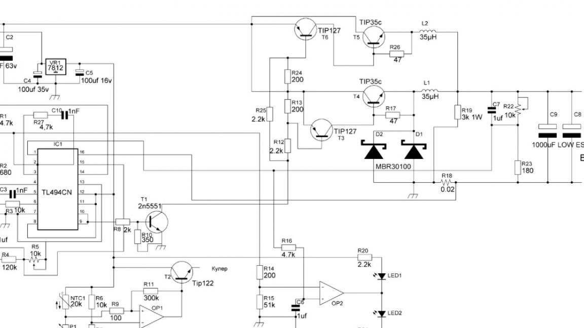
Its device is very complex, so we won’t go into work, if it is interesting to learn more about the circuit, then study it yourself.
It is time to move on to printed circuit boards. First, consider the power supply board.
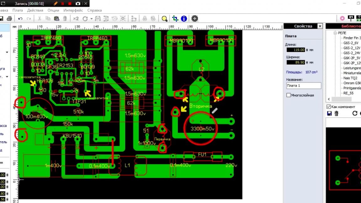
Neither capacitors nor a transformer fit on it, so there are holes on the board for connecting them. Select the dimensions of the filtering capacitor for yourself, as they come in different diameters.
Next, consider the converter board. Here, too, you can slightly adjust the placement of the elements. The author had to shift the second output capacitor up, as it did not fit. You can also add another jumper, this is at your discretion.
Now we proceed to etching the board.
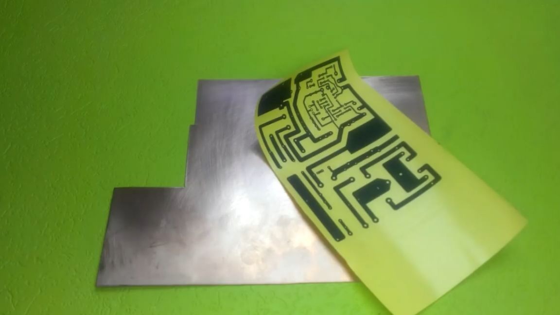
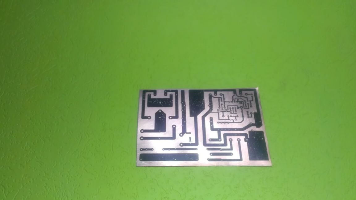
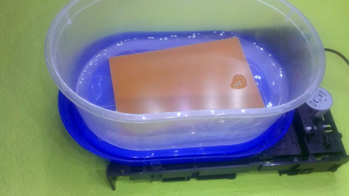
I think there is nothing complicated.
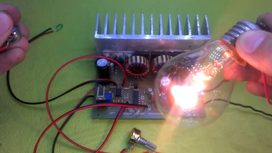
It remains to solder the circuit and you can conduct tests. First of all, we solder the power supply board, but only the high-voltage part, in order to check if we screwed up during the wiring. The first inclusion as always through an incandescent lamp.
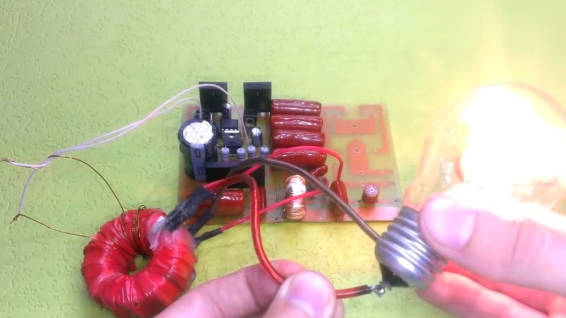
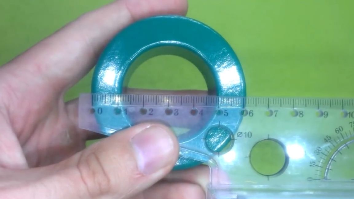
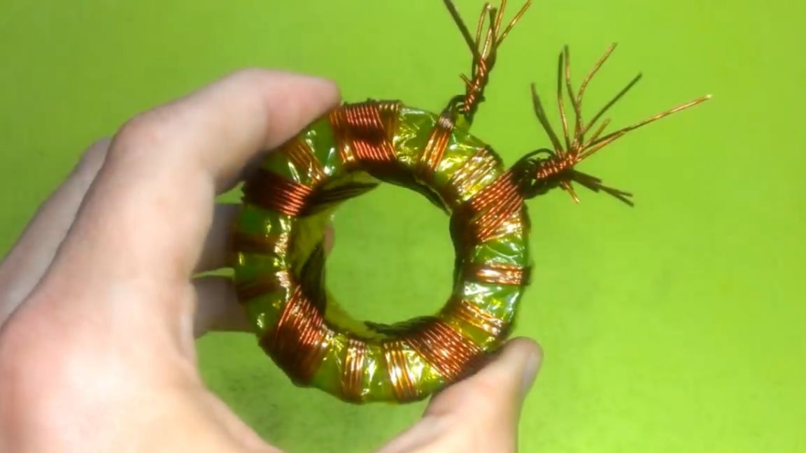
As you can see, when the light bulb is connected, it lights up, which means that the circuit is error-free. Well, you can install the elements of the output circuit, and as you know, you need a choke there. It will have to be made independently. As a core, we use this yellow ring from a computer power supply:
It is necessary to remove the standard windings from it and wind it up, with a 0.8 mm wire folded into two cores, the number of turns is 18-20.

At the same time, we can reel a throttle for a dc-dc converter. The material for winding are such powdered iron rings.

In the absence of this, you can apply the same material as in the first throttle. One of the important tasks is to maintain the same parameters for both chokes, as they will work in parallel. The wire is the same - 0.8 mm, the number of turns 19.
After winding, we check the parameters.
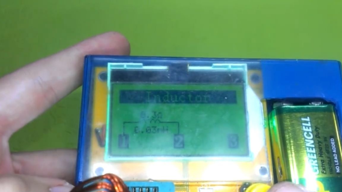
They basically coincide. Next, solder the dc-dc converter board. There should not be any problems with this, as the denominations are signed. Everything is classic here, first passive components, then active, and lastly, microcircuits.
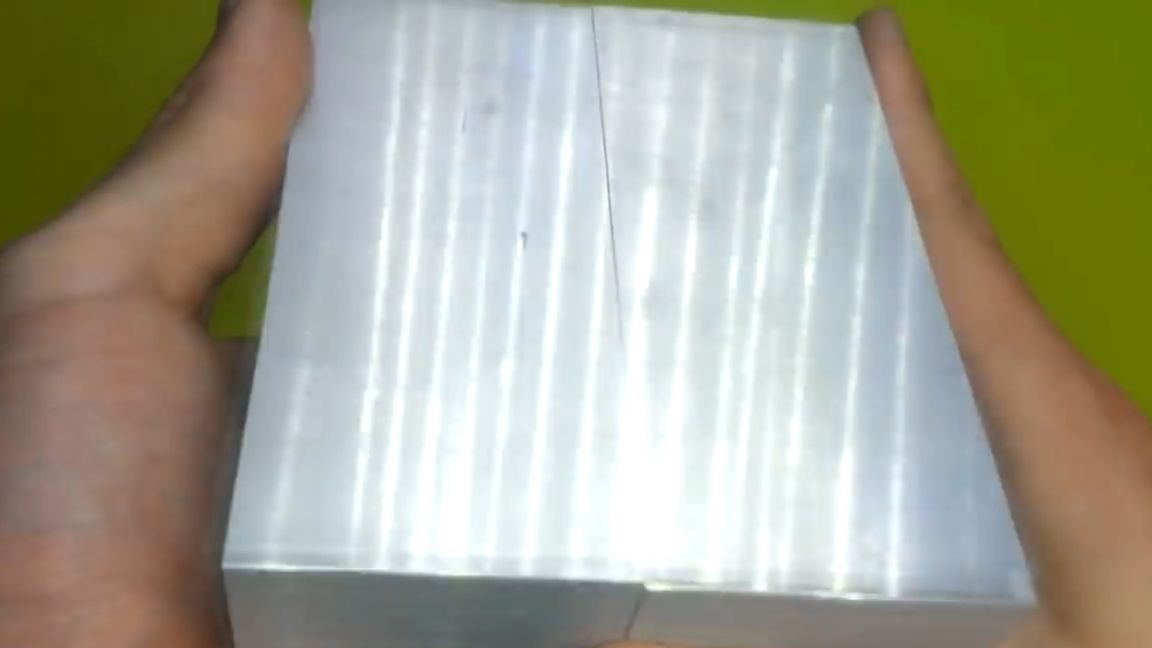
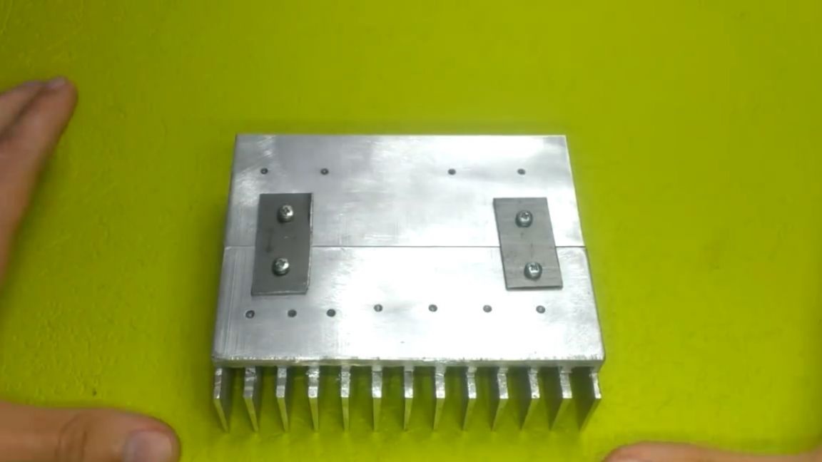
It is time to start preparing the radiator and case. We connect the radiators to each other with two plates in this way:
In words, this is all well and good. We drill holes for power elements, cut the thread.
The case itself is also a little tweak, breaking off the extra protrusions and partitions.
When everything is ready, we proceed to fastening the parts to the surface of the radiator, but since the flanges of the active elements have contact with one of the terminals, it is necessary to isolate them from the body with substrates and washers.
We will fasten it to the m3 screws, and for better thermal transfer we will use non-drying thermal grease.
When all the heating parts are placed on the radiator, we solder previously not installed elements on the converter board, and also solder the wires for resistors and LEDs.
Now you can test the board.To do this, apply voltage from the laboratory power supply in the region of 25-30V. Let's do a quick test.
As you can see, when the lamp is connected, the voltage is regulated, as well as current limits. Excellent! And this board is also without jambs.
You can immediately adjust the temperature of the cooler. Using the tuning resistor, we calibrate.
The thermistor itself needs to be mounted on the radiator. It remains to wind the transformer for the power supply on such a giant core:
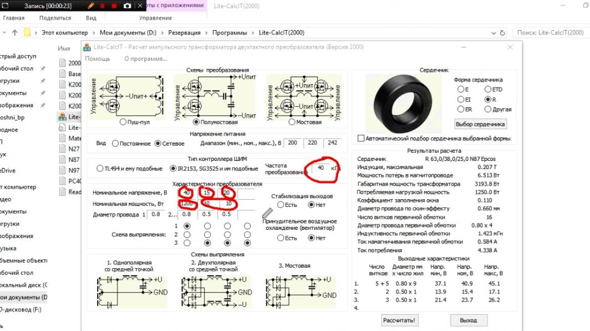
Before winding, it is necessary to calculate the windings. We will use a special program (you will find a link to it in the description under the author’s video by clicking on the “Source” link). In the program, indicate the size of the core, the conversion frequency (in this case, 40 kHz). We also indicate the number of secondary windings and their power. Power winding at 1200 watts, the rest at 10 watts. You also need to indicate which wire the windings will be wound, click the "Calculate" button, there is nothing complicated, I think you will figure it out.
We calculated the parameters of the windings and begin manufacturing. The primary in one layer, the secondary in two layers with a tap from the middle.
Isolate everything with a thermal tape. Here, in fact, the standard winding of the impulse.
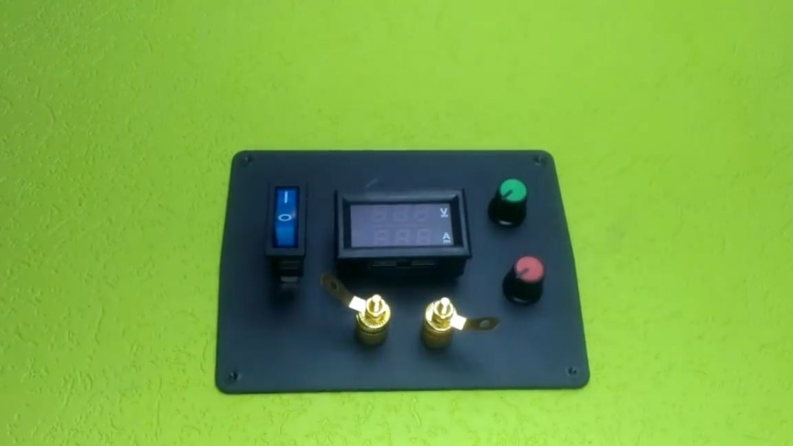
Everything is ready for installation in the case, it remains to place the peripheral elements on the front side in this way:
This can be done quite simply with a jigsaw and a drill.
Now the hardest part is placing everything inside the enclosure. First of all, we connect two radiators into one and fix it.
We will conduct the connection of the power lines with such a 2-mm core and a wire with a cross-section of 2.5 squares.
Also, there were some problems with the fact that the radiator occupies the entire rear cover, and there it is impossible to bring out the wire. Therefore, we display it on the side.

That's all, the assembly is complete. Before closing the lid we conduct a test inclusion.
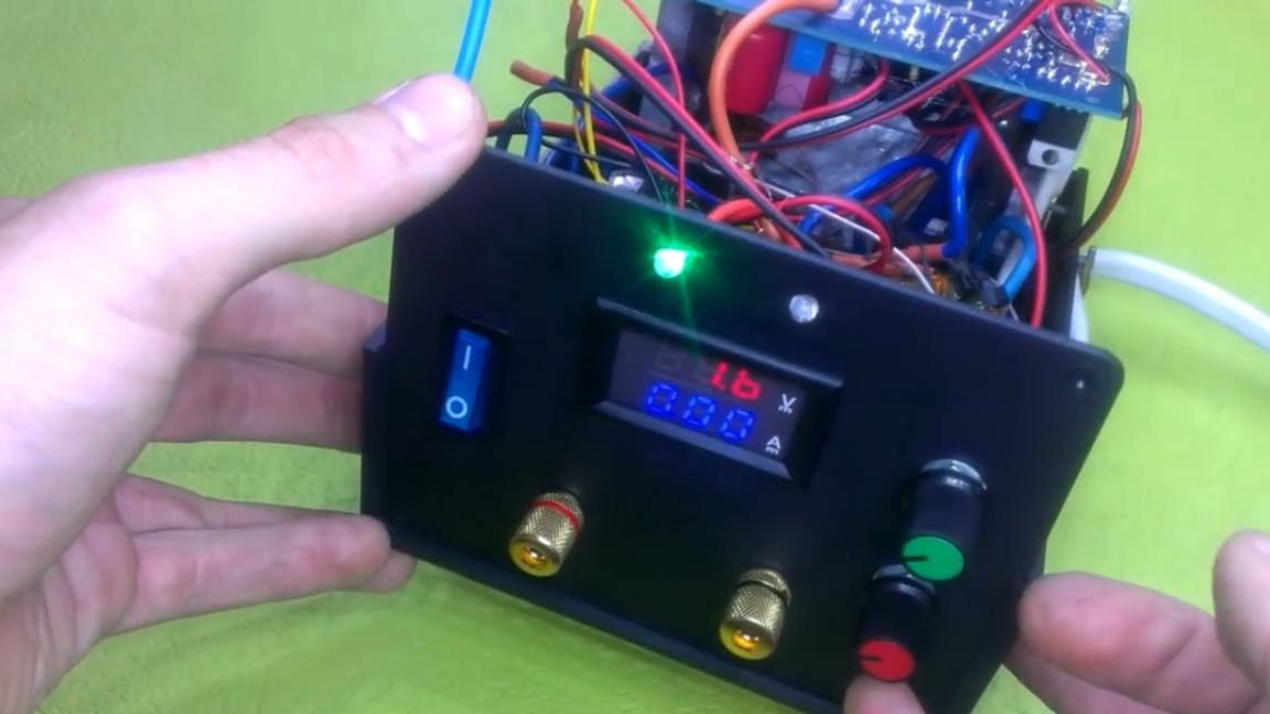
The unit wound up, now close the top cover and go to test. For the test, we first use incandescent bulbs at 36V 100W.
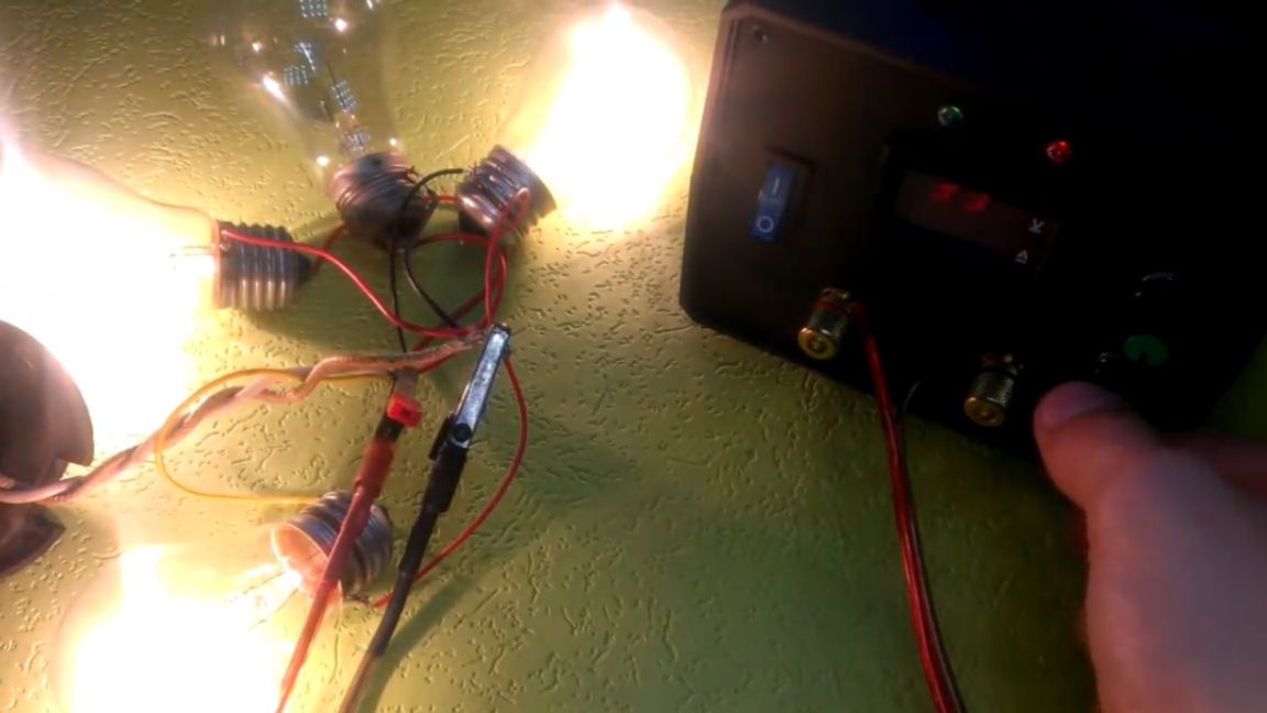
As you can see, the block holds them without difficulty. This voltammeter, which the author bought, cannot measure the maximum current of the unit even with a shunt, although it is written on the site that with a shunt can measure up to 50A. Do not make the same mistake and take yourself a dial ammeter - it will be more reliable. And about the test - do not worry, now you will see that the maximum current of the device is over 25A. To do this, use a 25A fuse and short circuit it.
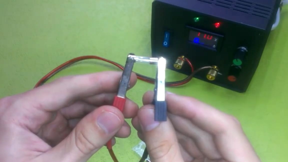
It simply melts, which means that the current here is more than 25 amperes. Also try to melt various objects.
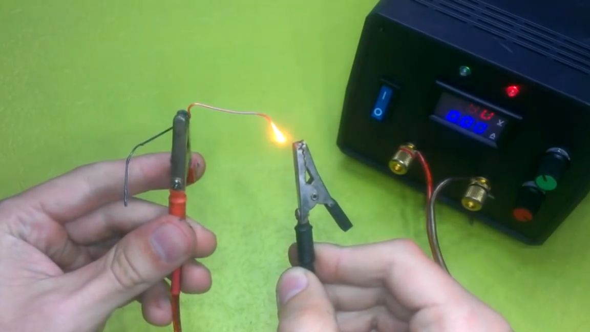
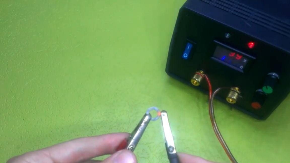
A paper clip, a puck, and even an awl - nothing could resist the power of this unit.
Thank you for attention. See you soon!
Video: