
In this article, AKA KASYAN will show you how to build an “eternal match”. Of course, not entirely eternal.
Classically, such products are a small sealed container, with combustible liquid fuel inside. The second element of such devices is flint, teal.
In short, it is a cross between a lighter and a match.
Naturally, they are not eternal. The fuel runs out, and flint, wick, and other parts also wear out.
The author is friends with electronics, and mechanical troubles are not his topic. He will make an unusual electronic a match.
The author's version belongs to the class of plasma or electric arc.
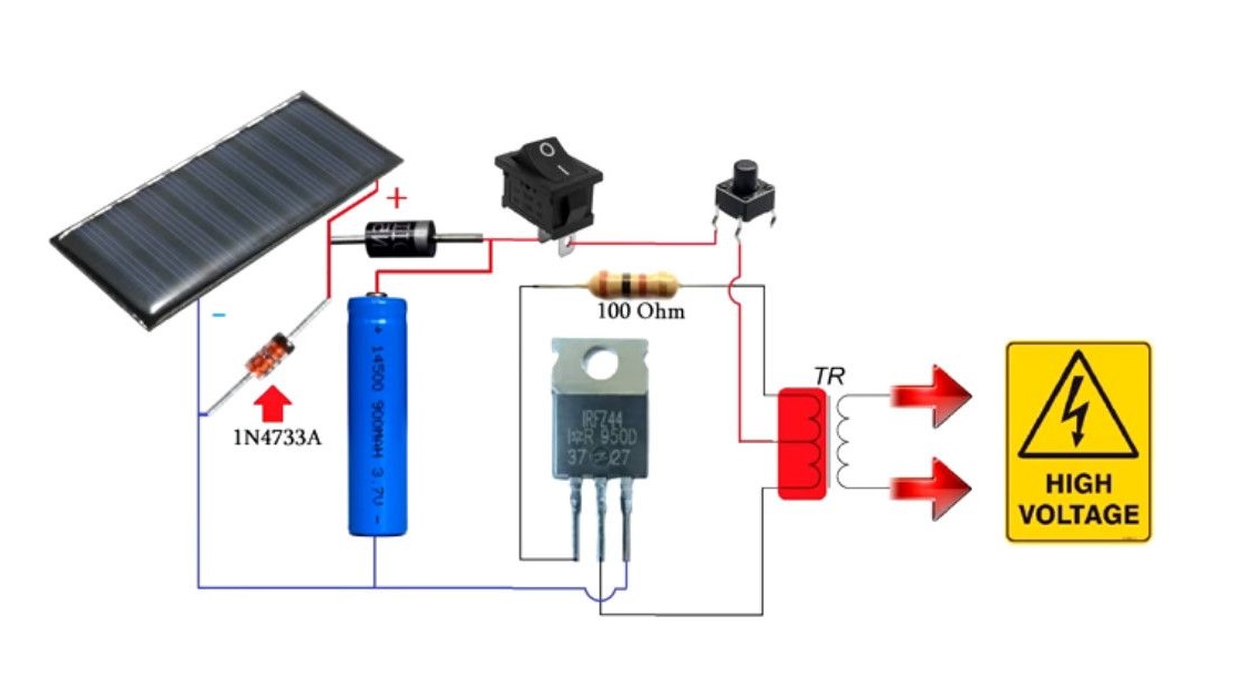
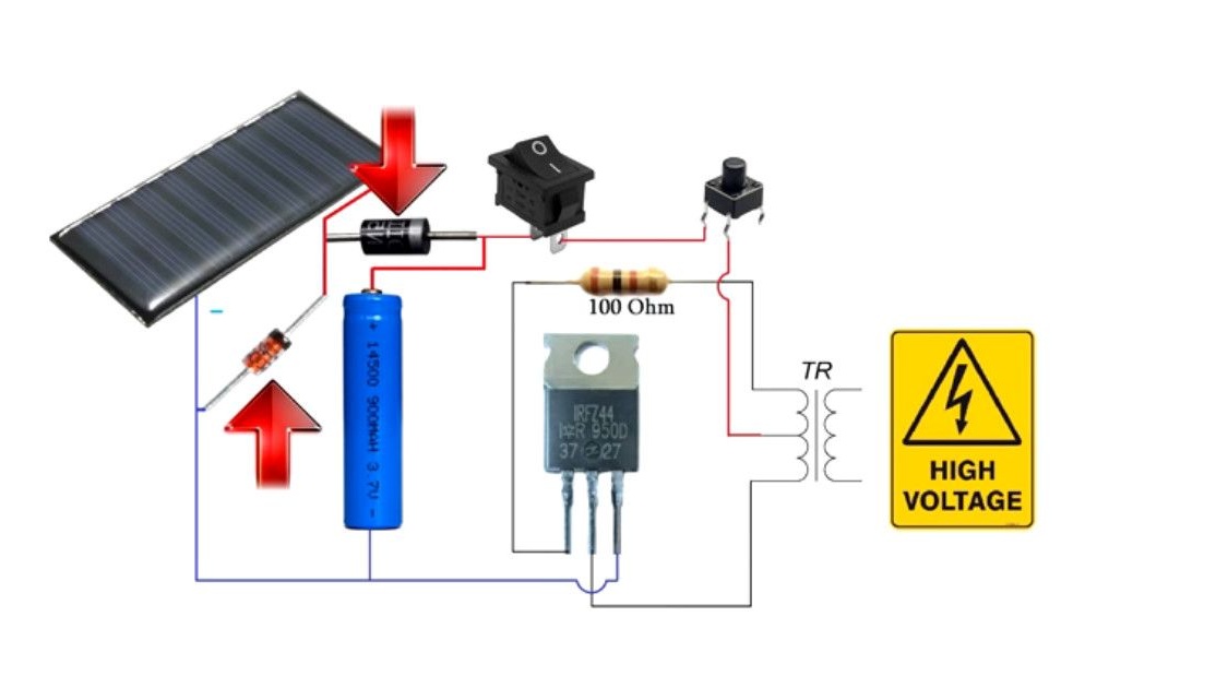
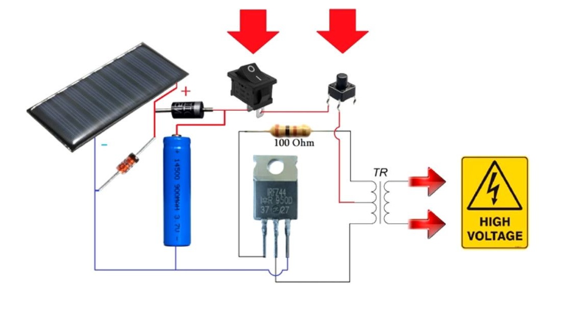
The main components.
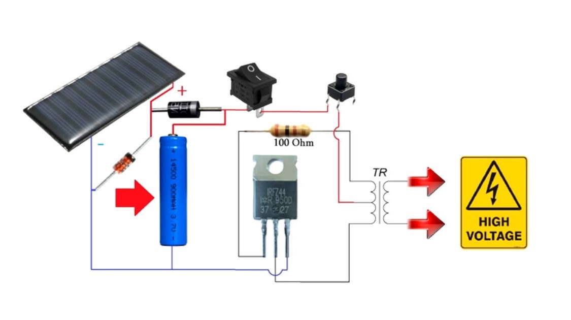
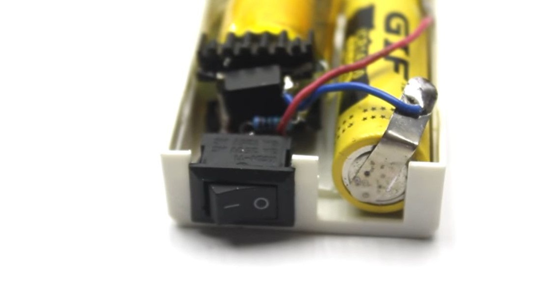
The main power source is a 3.7V battery.
High voltage voltage converter.
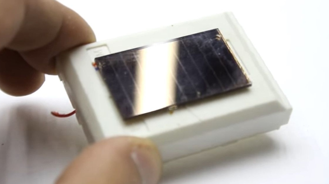
Additional power source, solar panel.
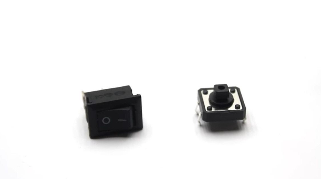
Clock button and ON / OFF switch.
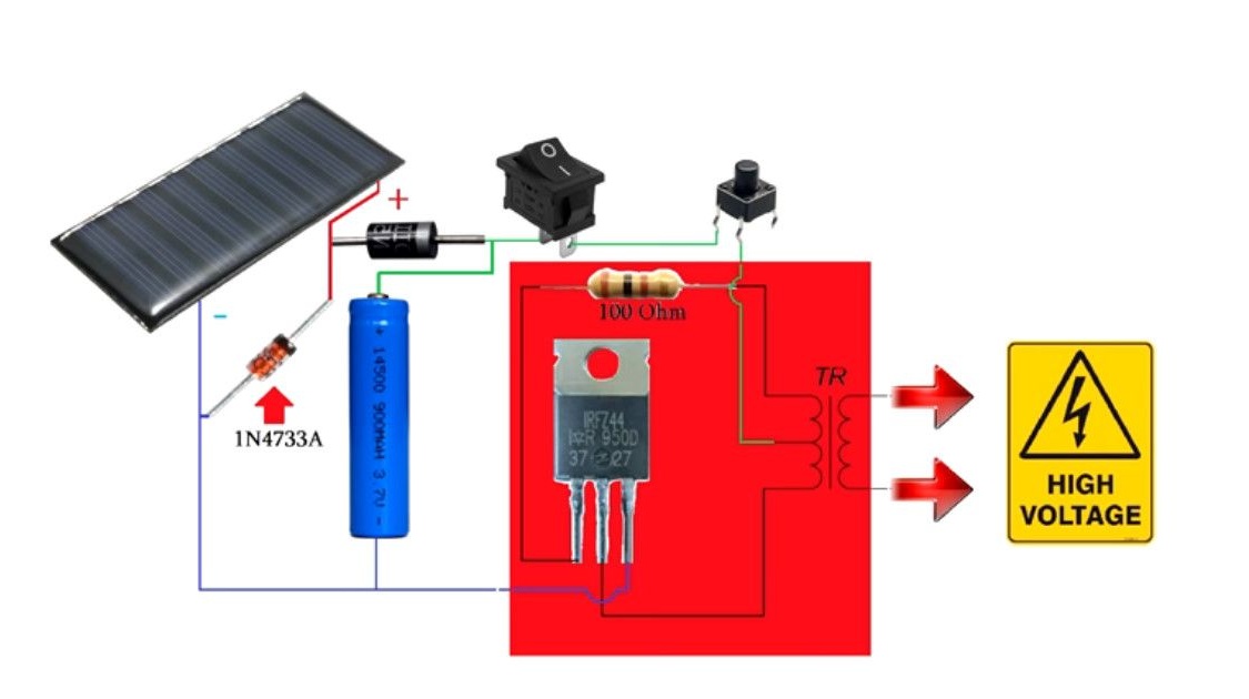
The battery charging unit is a regular diode and a zener diode.
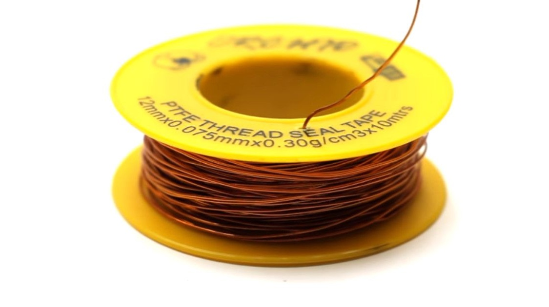
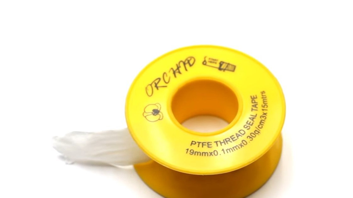
FUM tape or tape.
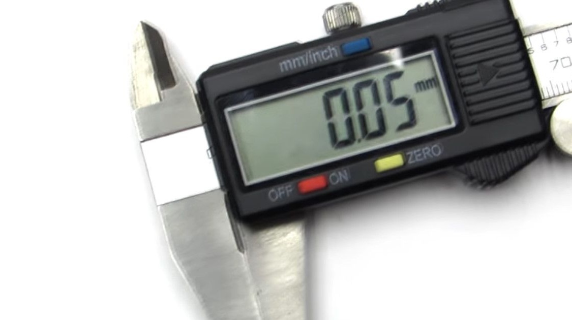
0.5mm and 0.05mm wires
The author will do the boost converter on his own. For lovers to wind transformers manually, you can skip part of the article and purchase one in China for a couple of dollars. Although the basics of making a transformer from trash - everyone should know, just in case;)
So, the converter is powered by a battery. The generated output voltage is several thousand volts.

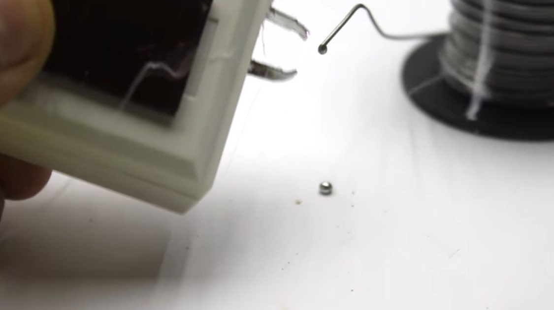
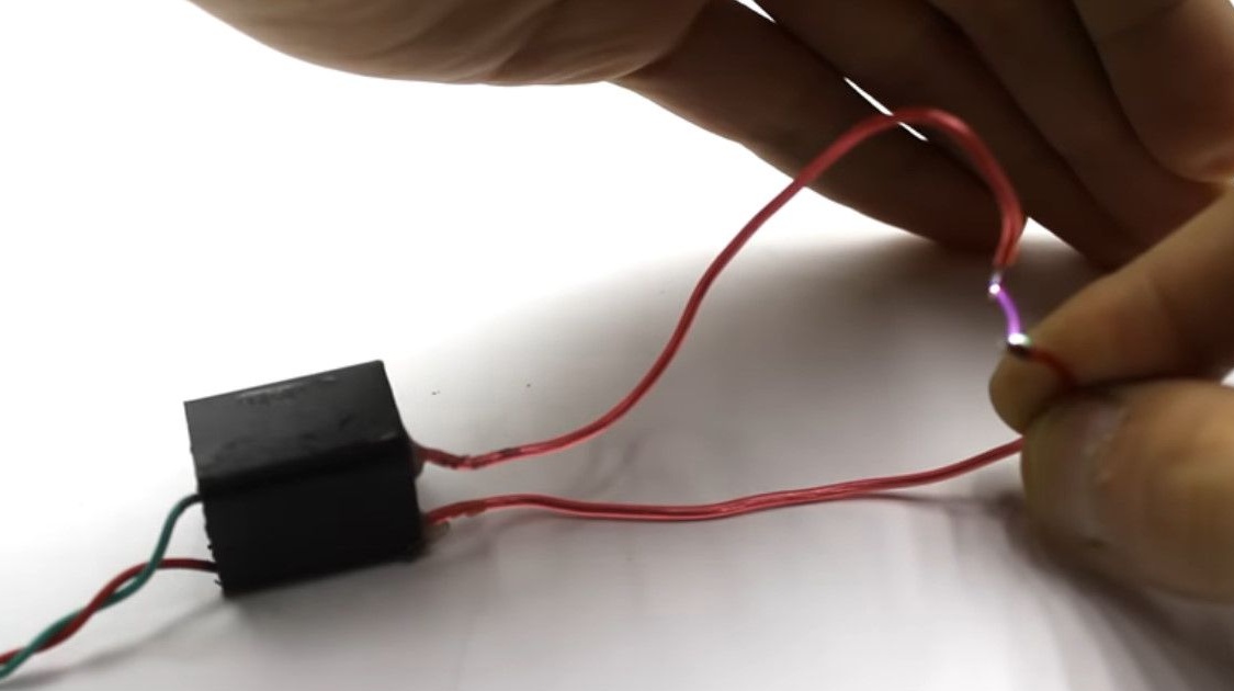
A high-frequency high-voltage arc having a very high temperature is formed on the electrodes.
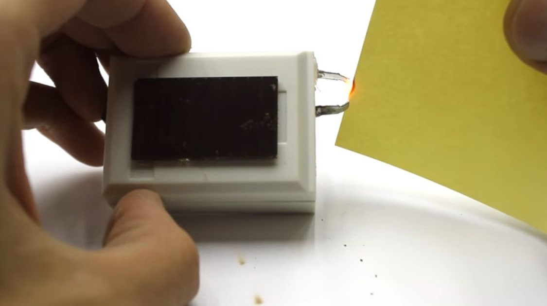
The arc can melt tin solder, even copper electrodes, from the sharp ends of which it is formed.
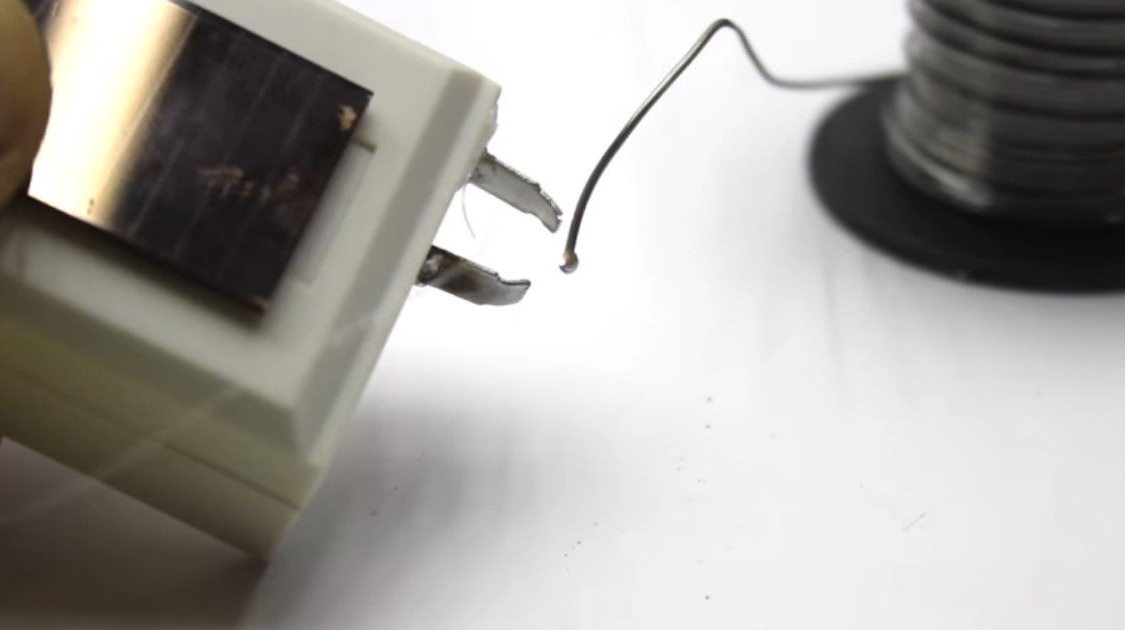
In short, to set fire to almost any combustible material for such a lighter is not difficult.
Dead or unnecessary switching power supply. From a computer, printer, scanner, or anything else.
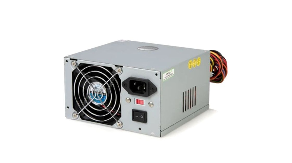
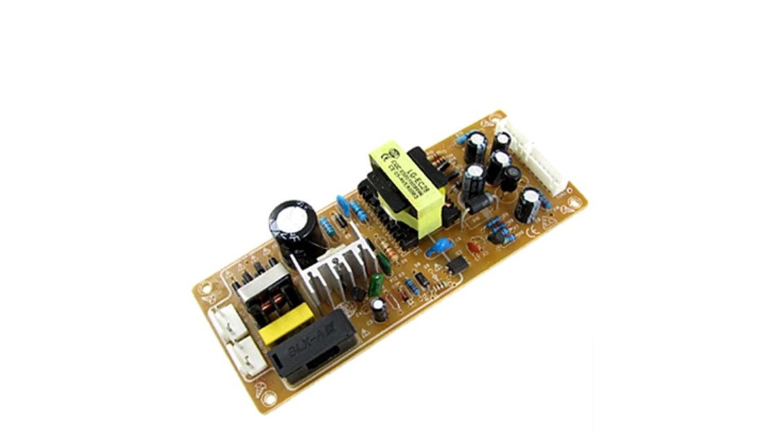
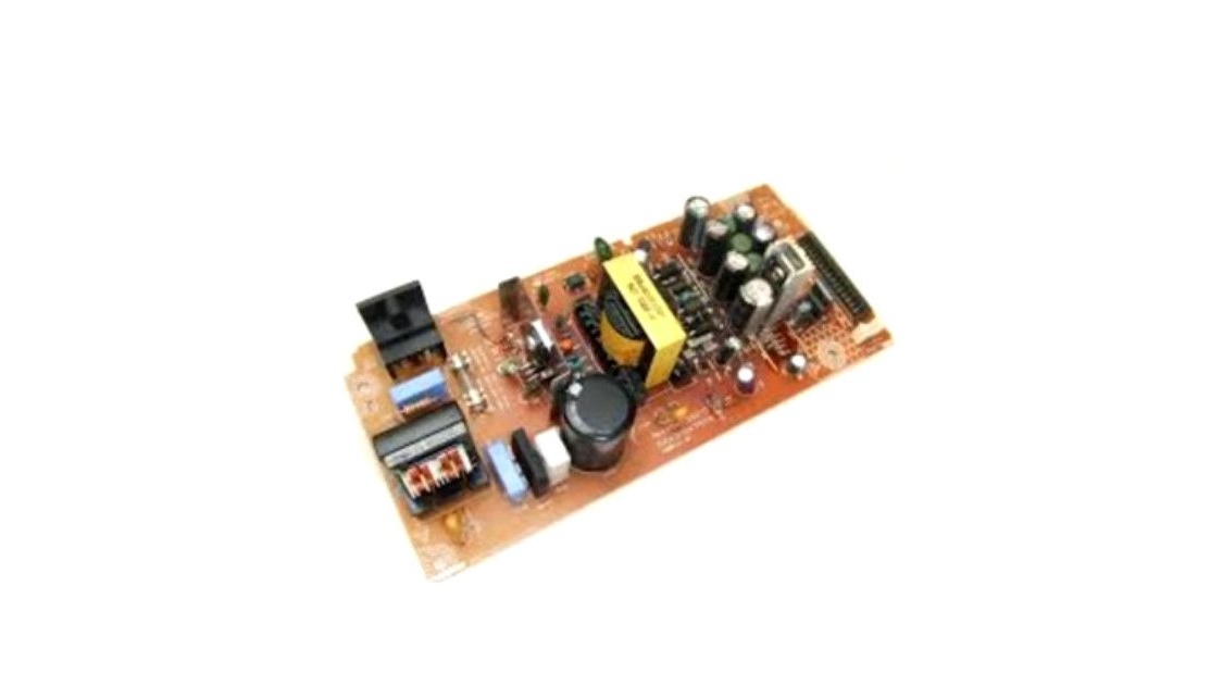
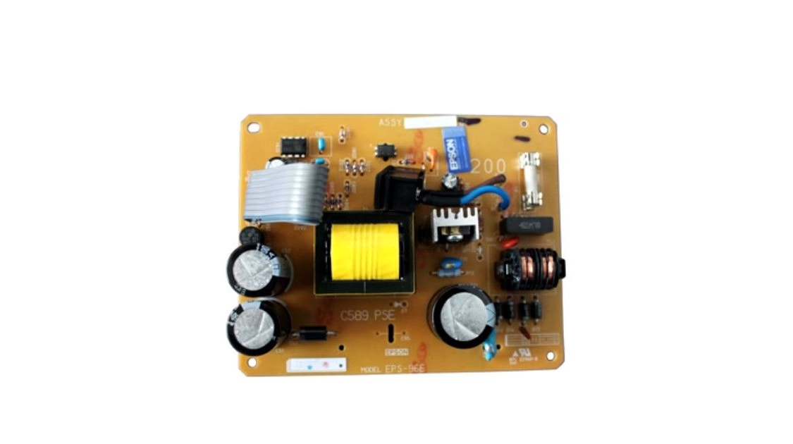
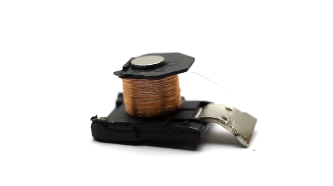
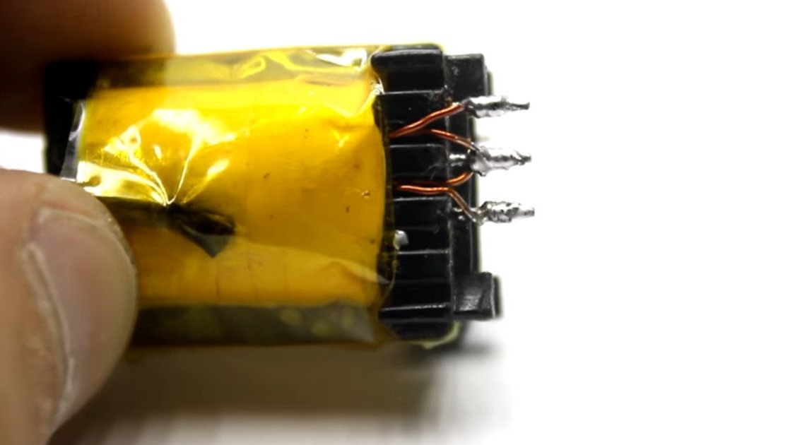
We confiscate a pulse transformer from it. It is on its basis that a high-voltage converter will be built.
The author takes the transformer from the standby power unit. This is a computer power supply almost completely stolen for spare parts.
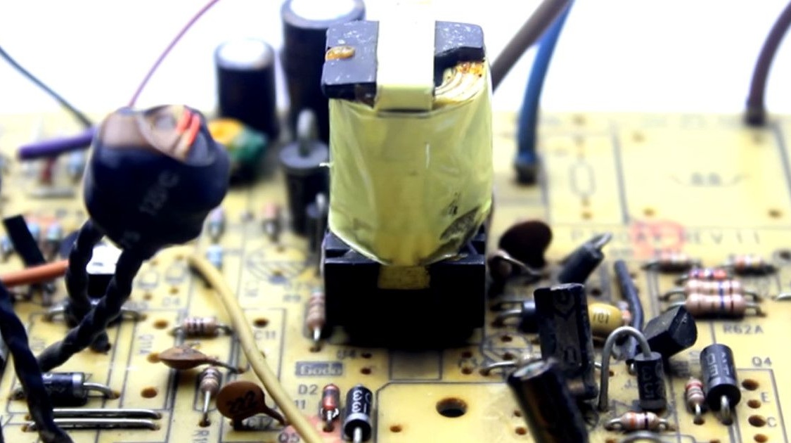
Try to choose the same as the author, with an elongated core.
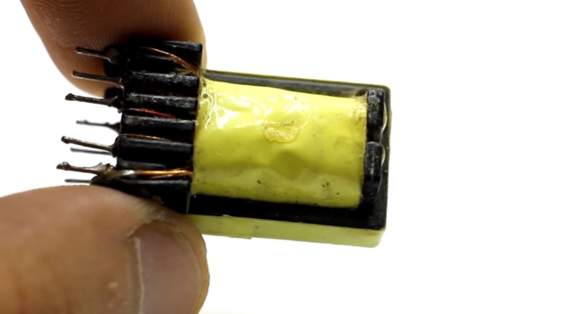
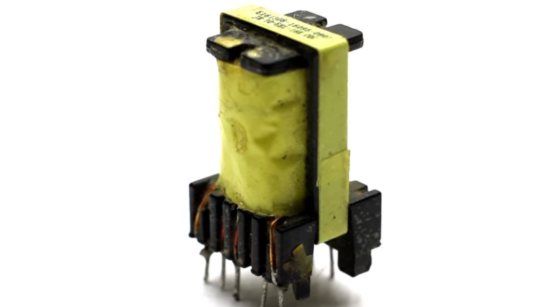
This will facilitate winding. Found transformer must be disassembled.
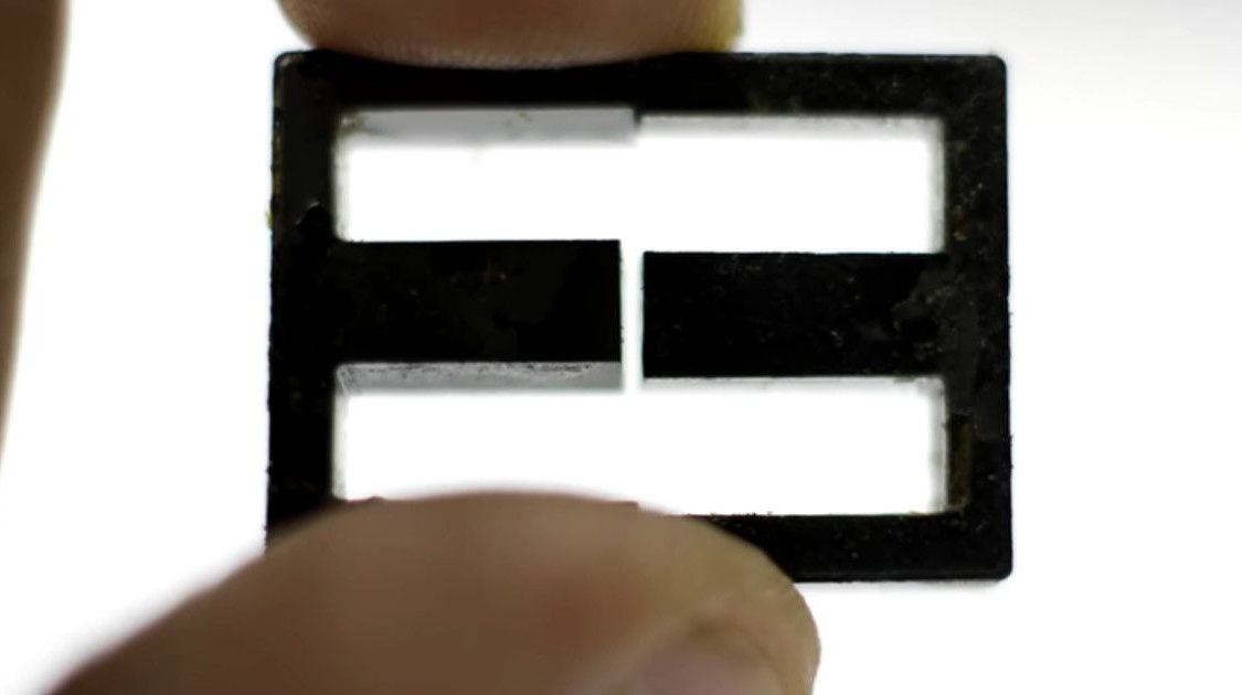
The ferrite core, as usual, is made of two W-shaped halves.
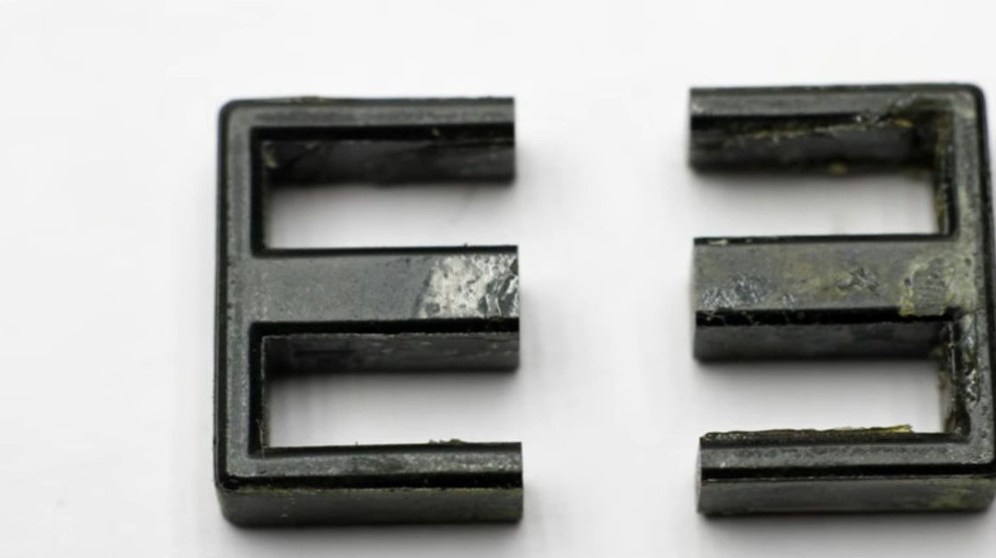
These halves are glued to each other. In order to disconnect, just warm up the core.
This action is carried out with a soldering iron, warming up the core for several minutes. You can also use a building hair dryer, oven, soldering station with a thermoduy. Use them with care, do not melt the plastic insert. The adhesive weakening temperature is usually 140-160 ° C.
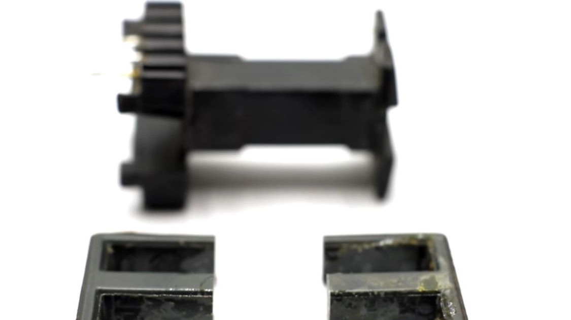
Separate the halves from one to the other.
The extracted halves have a gap between the central slats.
For the inverter circuit that the author applies, this non-magnetic gap is in good need.
Although the scheme will function without it.
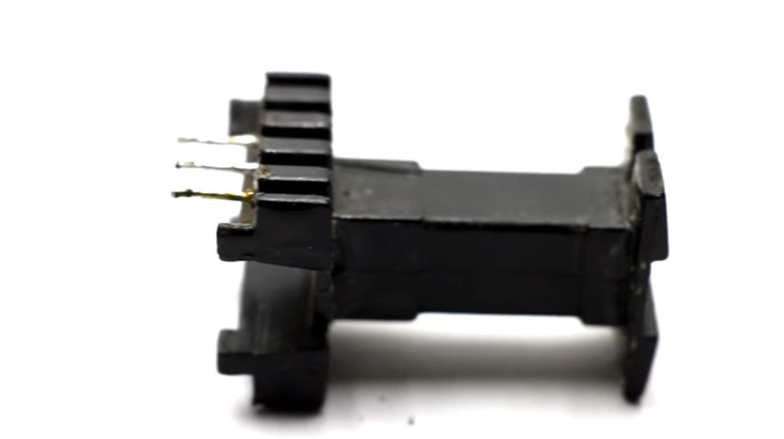
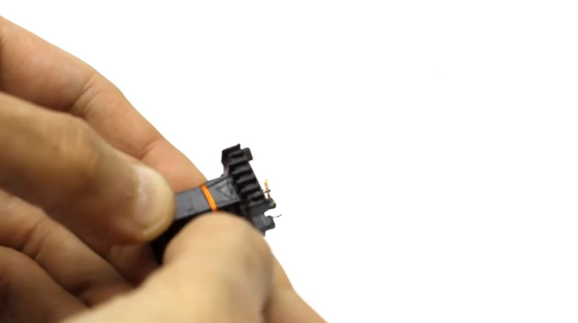
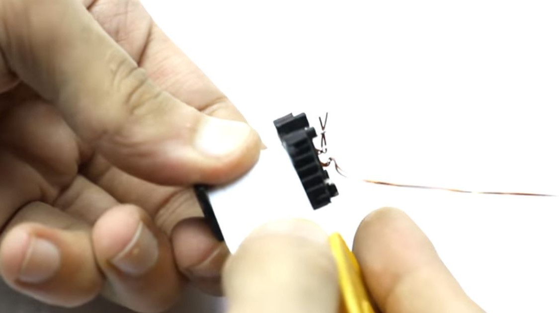
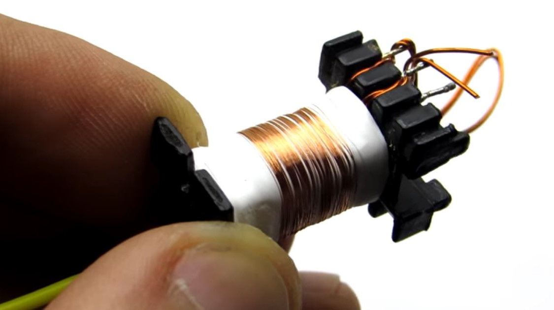
The author deleted the core, now it winds up all the available windings. Leave one plastic frame.
Starts winding the primary. She wound a 0.5mm wire after folding it in half.

The diameters of the wire used can be in the range from 0.2mm to 0.8mm
Thicker useless. Optimum diameters 0.4mm - 0.7mm.
Winding 8 turns.
Displays the second end of the winding.
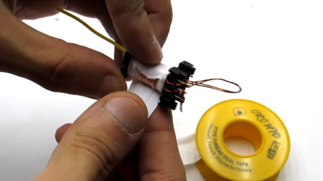
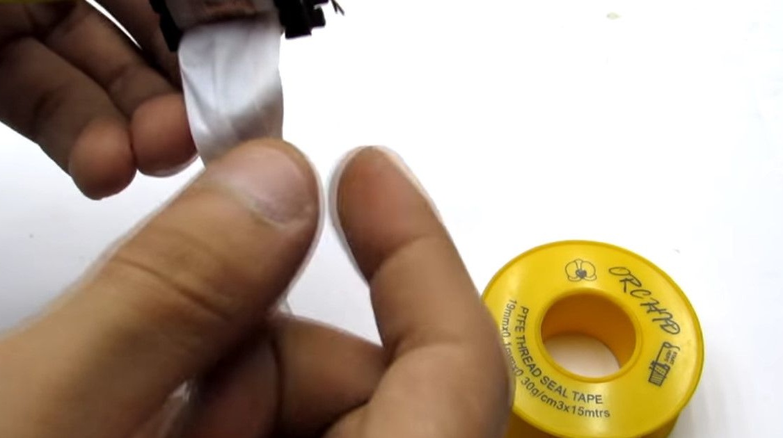
Isolates by wrapping several layers of fluoroplastic tape or usually transparent tape over the winding.
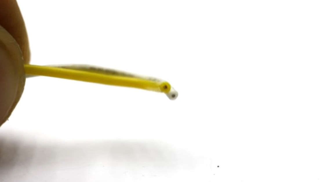
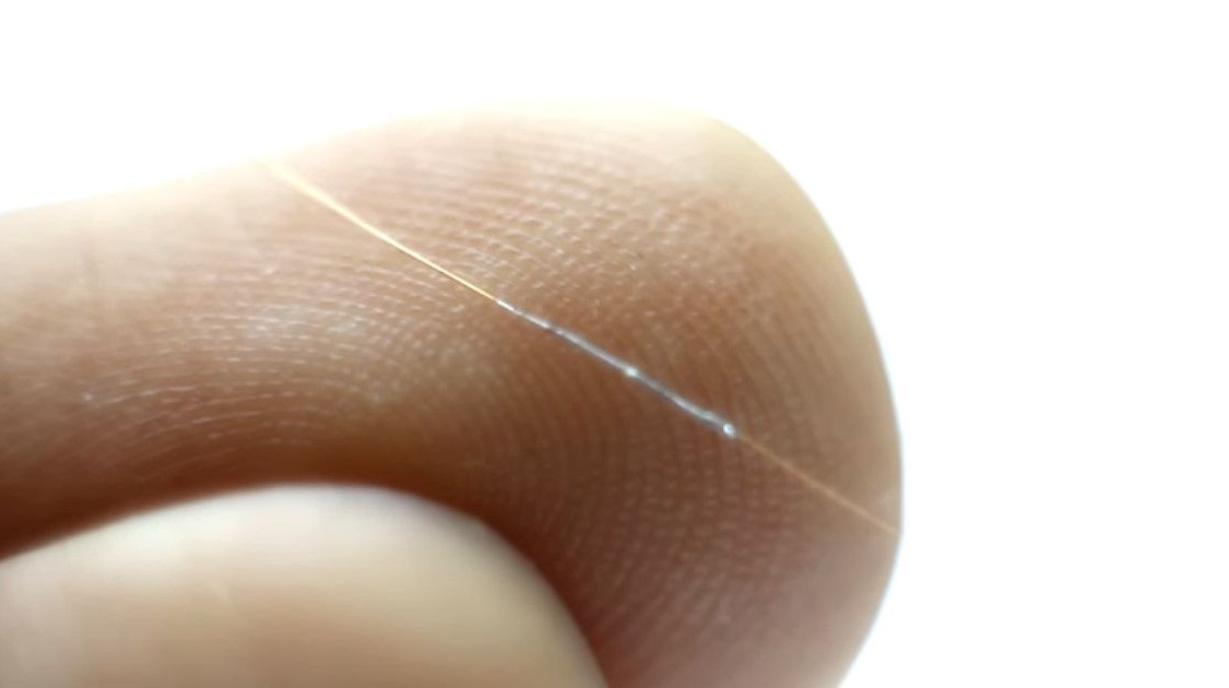
Next takes a thin wire.

The author took it from the coil of a 12-volt reel.
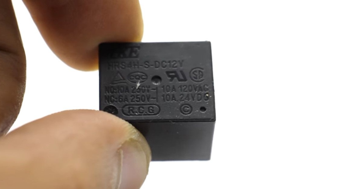
Actually, there is a thin wire in the secondary windings of 5V - 12V low-power transformers. The required wire thickness is about 0.05 mm.
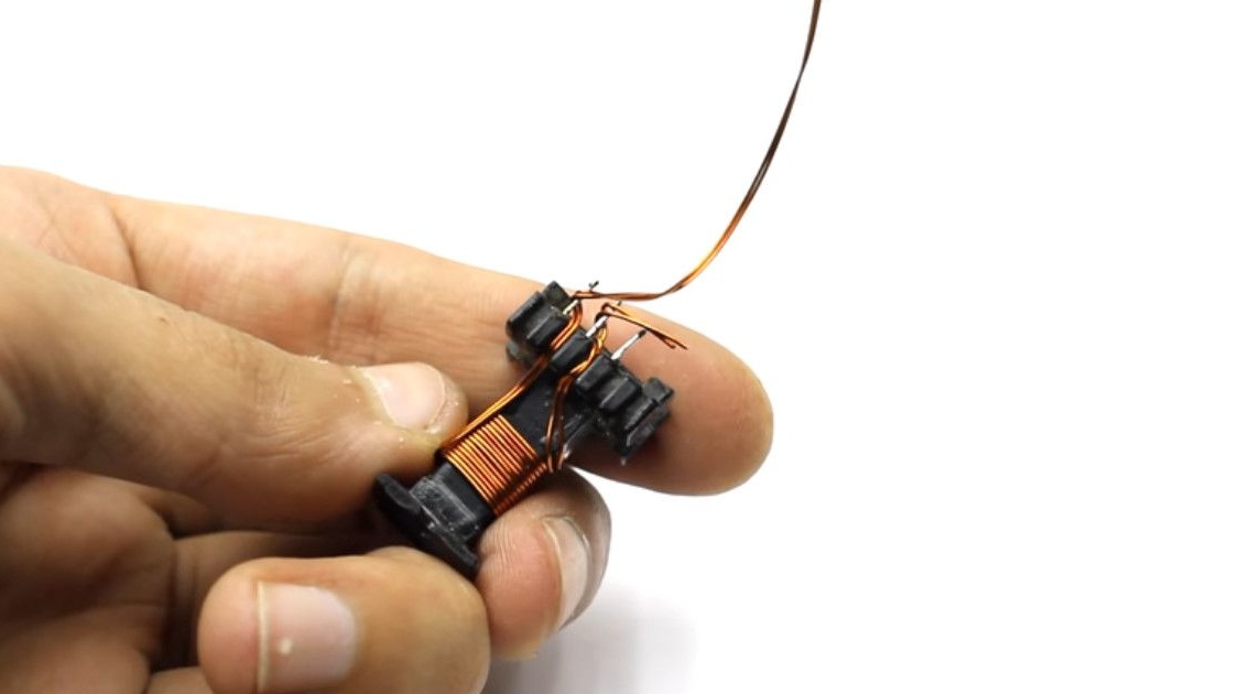
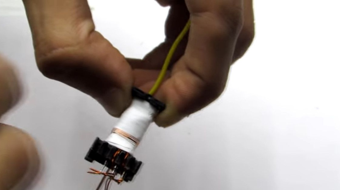
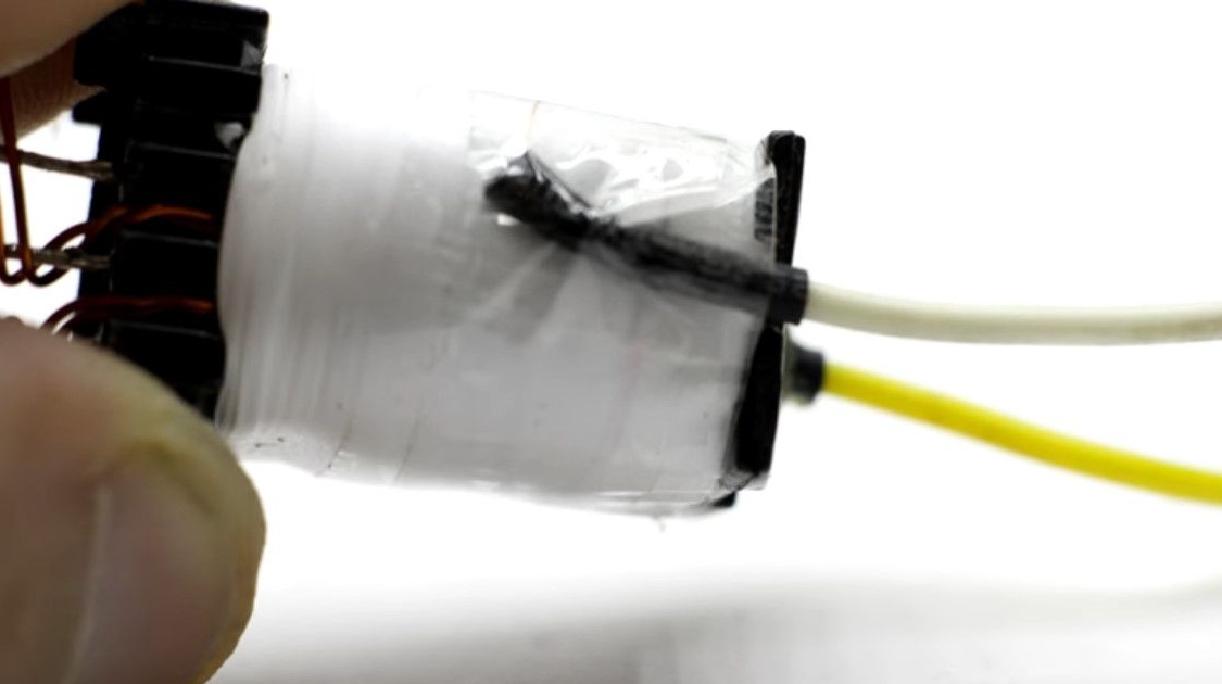
A multicore high-voltage wire with a thick insulating layer is soldered to the beginning of the secondary winding.
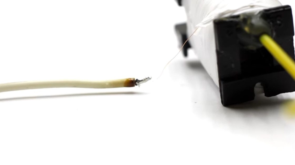
The soldering place is insulated with a heat shrink tube, choose two-layer tubes, with glue inside.
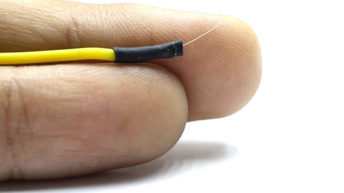
Leads the wire and fixes with hot melt adhesive. For additional insulation and high-quality fixation.
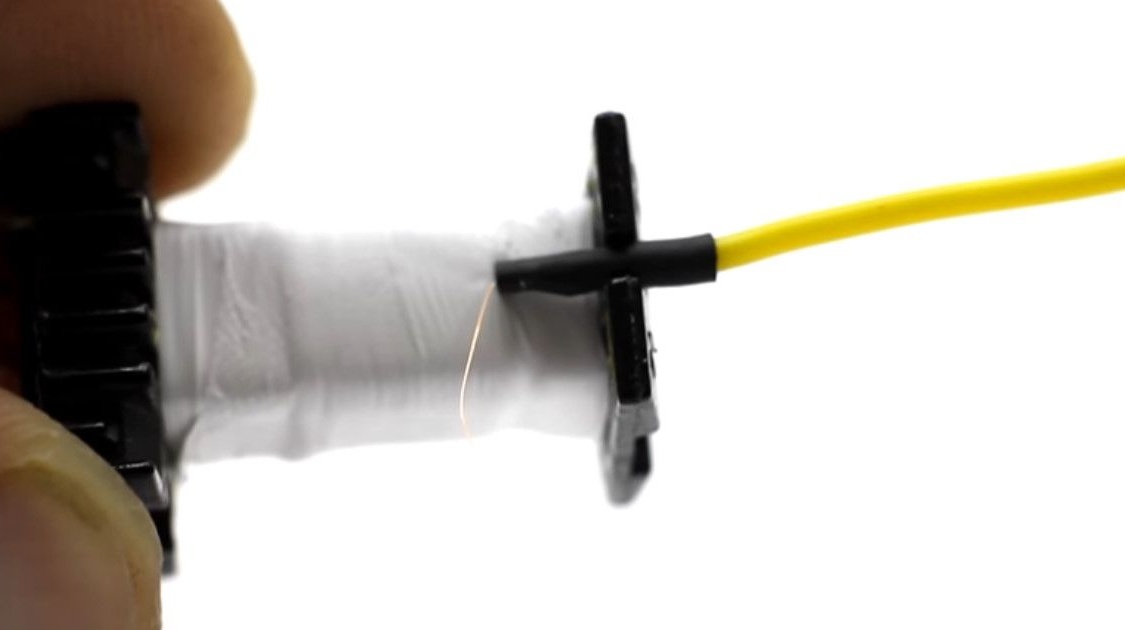
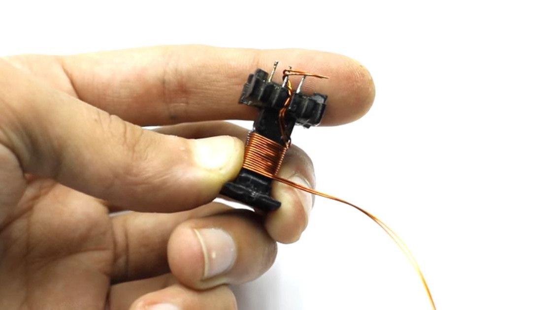
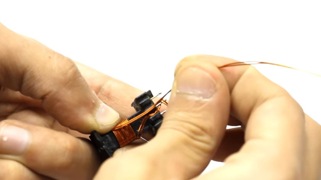
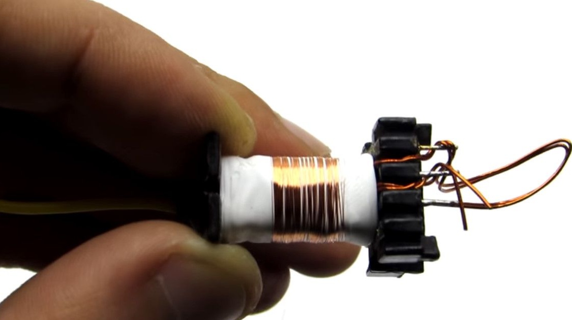
Starts winding the secondary winding. It is difficult to wind a little thread to a small thread, but it is not necessary. Just do it carefully.
Each layer of the winding consists of one hundred to eleven turns.
Between each layer we must isolate in 2-3 layers of insulation.
In order to avoid breakdown, the interlayer transition is done inside the insulation, not reaching the edge.
We wrap the first layer from left to right, the second - in the opposite direction.
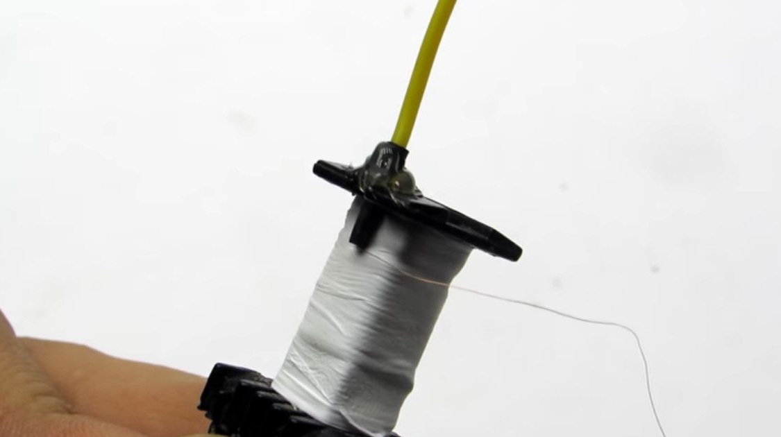
According to this principle, isolating each layer, we wind ten to twelve layers. The number of layers is always even so that both outputs come out on the same side.
The secondary winding, as a result, will have to consist of 1000 - 1440 turns.
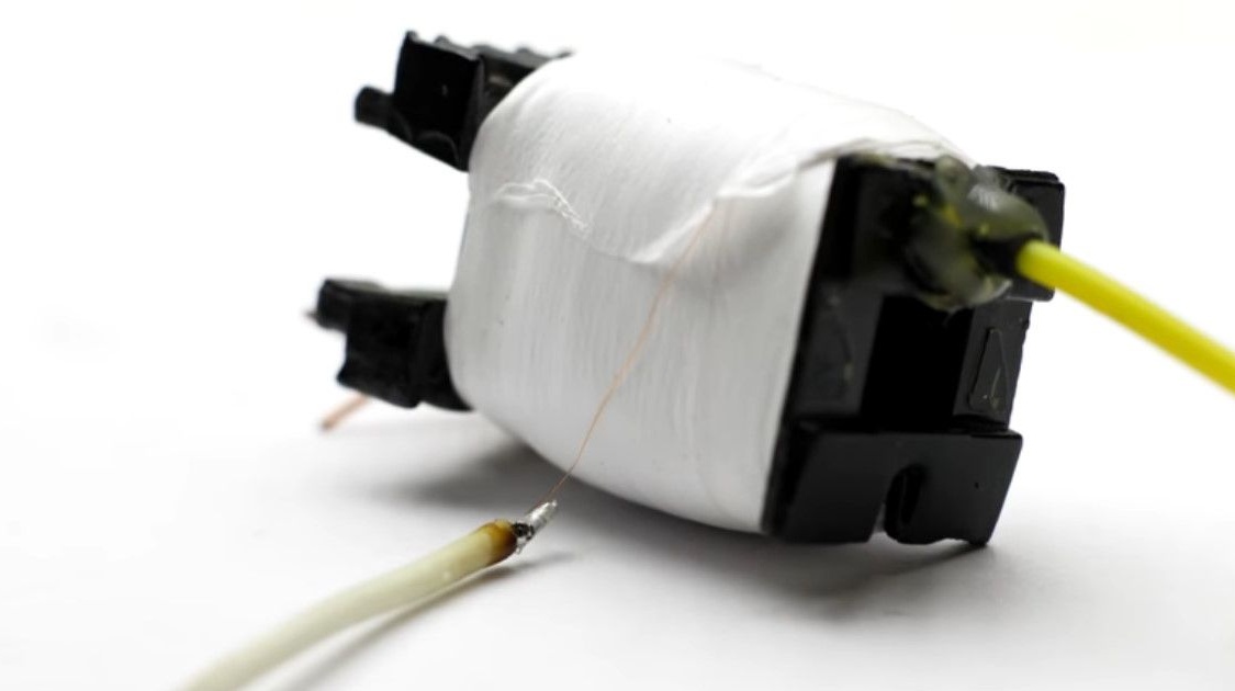
After winding, we cut the wire, solder the multicore explosive wire, isolate the soldering place. In general, the same as at the beginning of it.
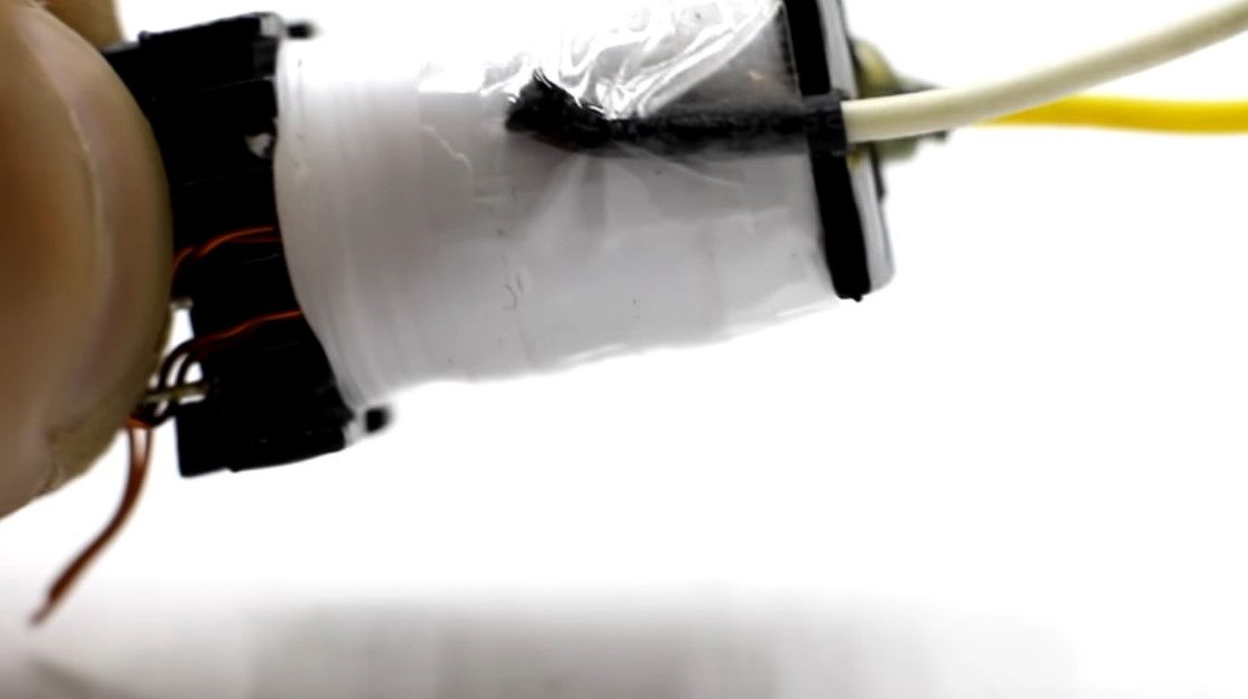
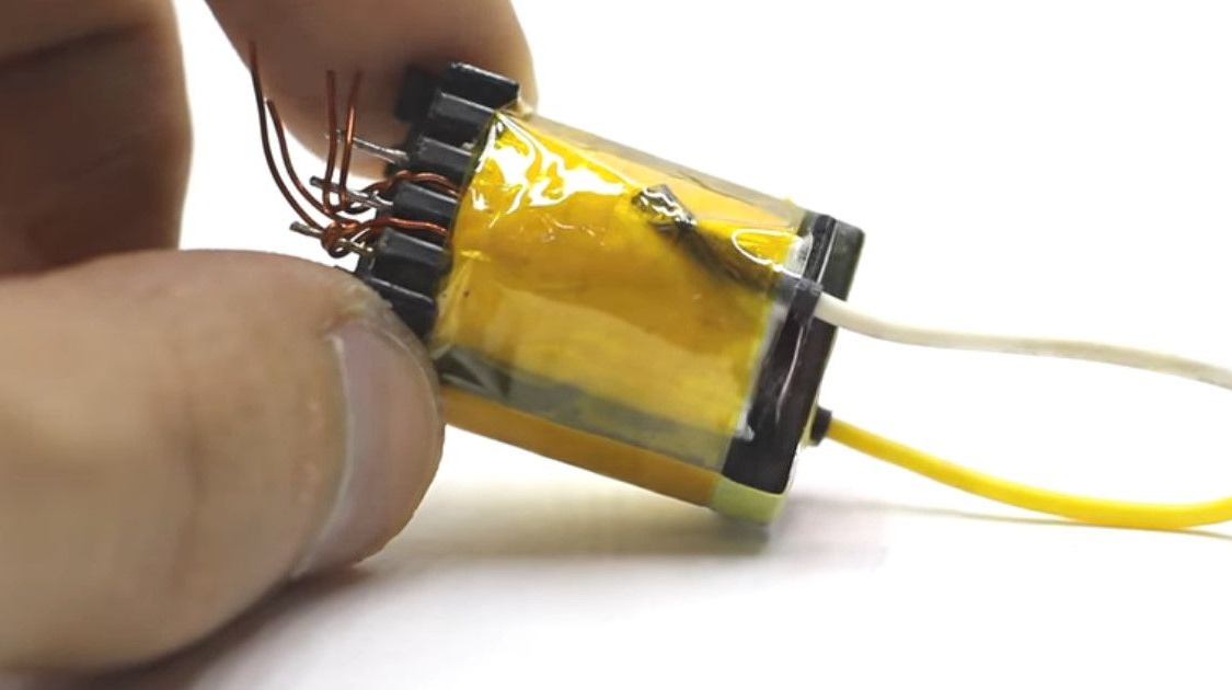
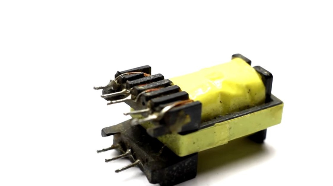
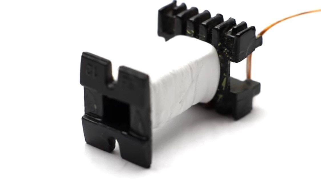
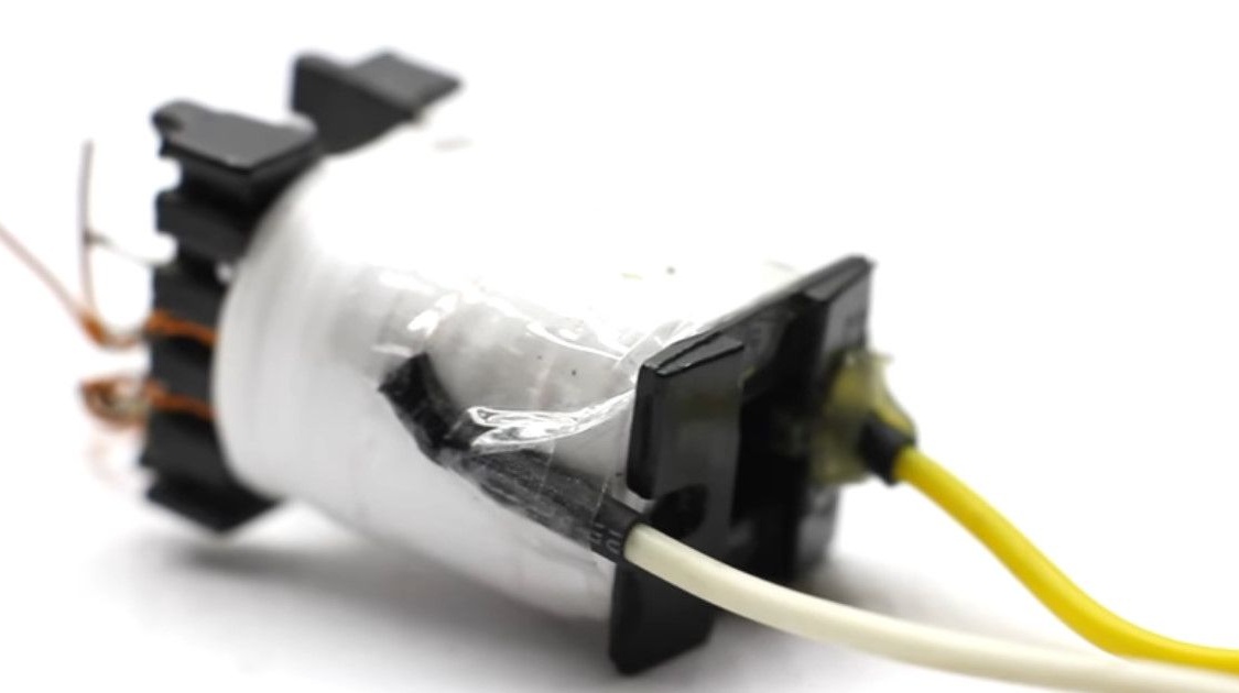
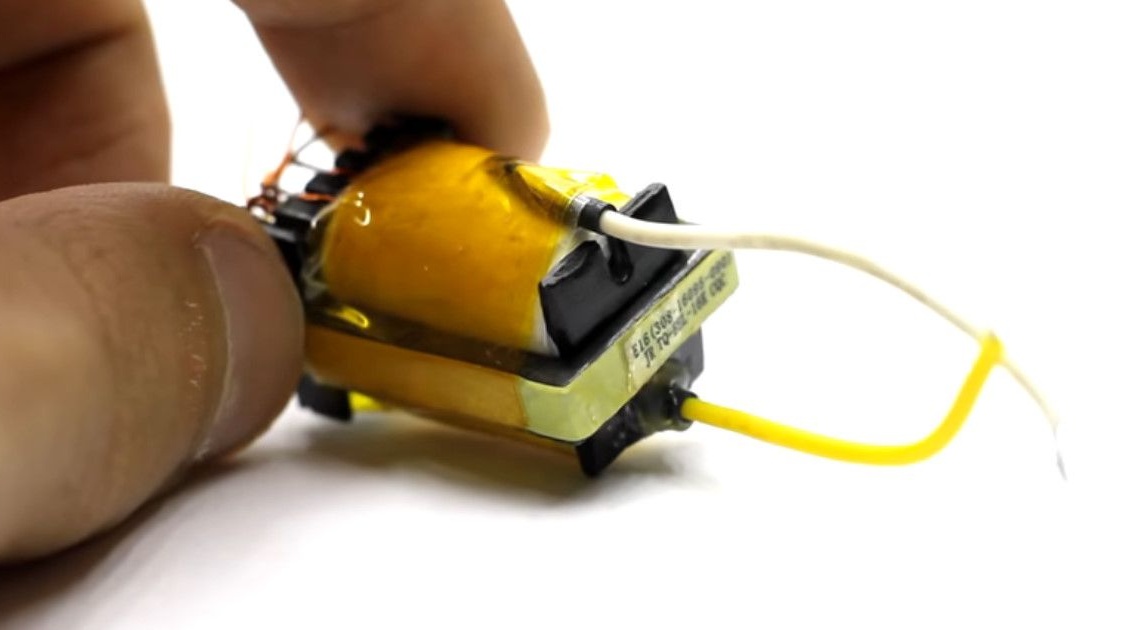
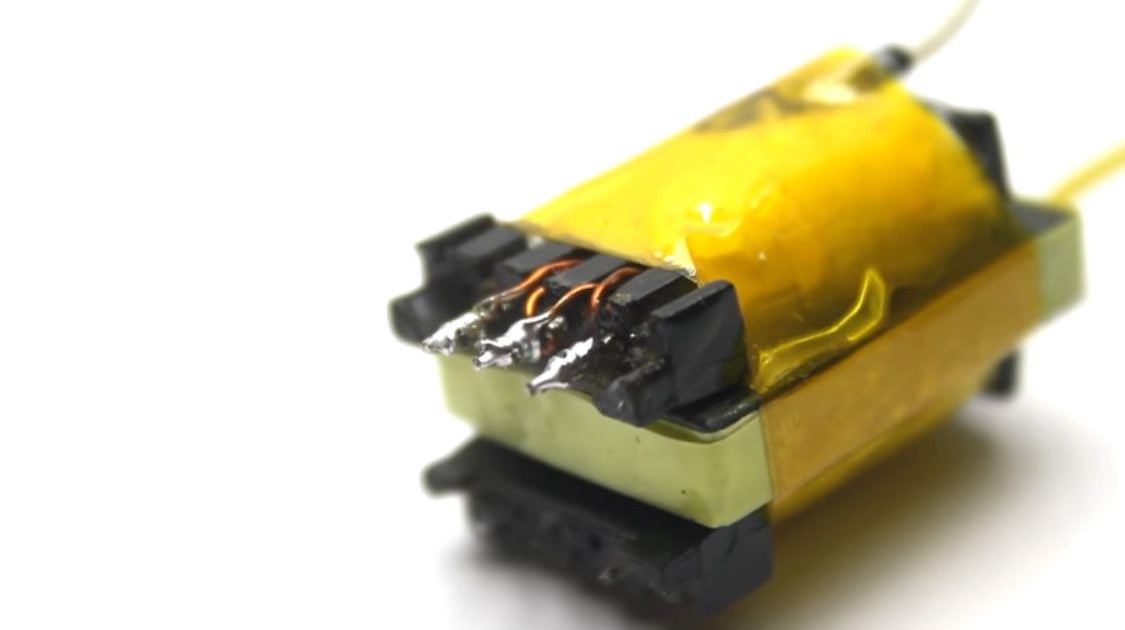
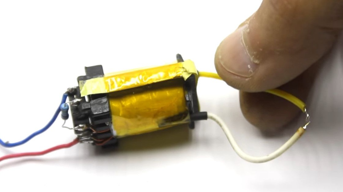
Finally fixes all the windings in several layers of adhesive tape.
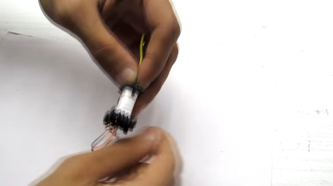
Assembles the transformer in reverse order.
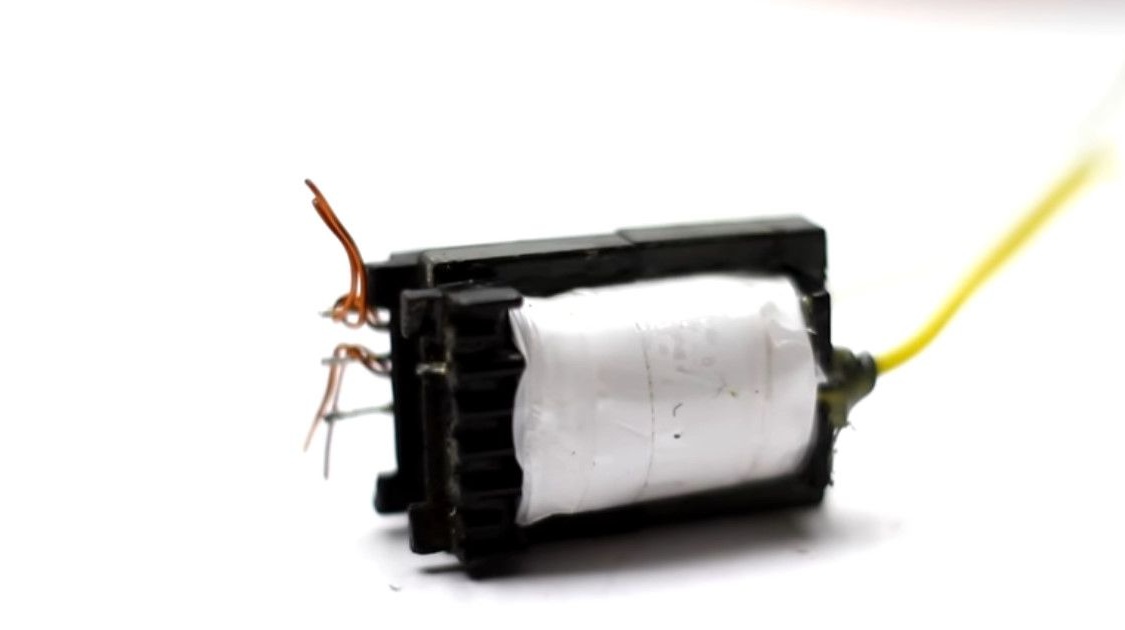
Having installed the halves of the core, it fixes it with heat-resistant tape again.
If the wire breaks during the winding process of the secondary, you can solder it, but strengthen the insulation in this place.

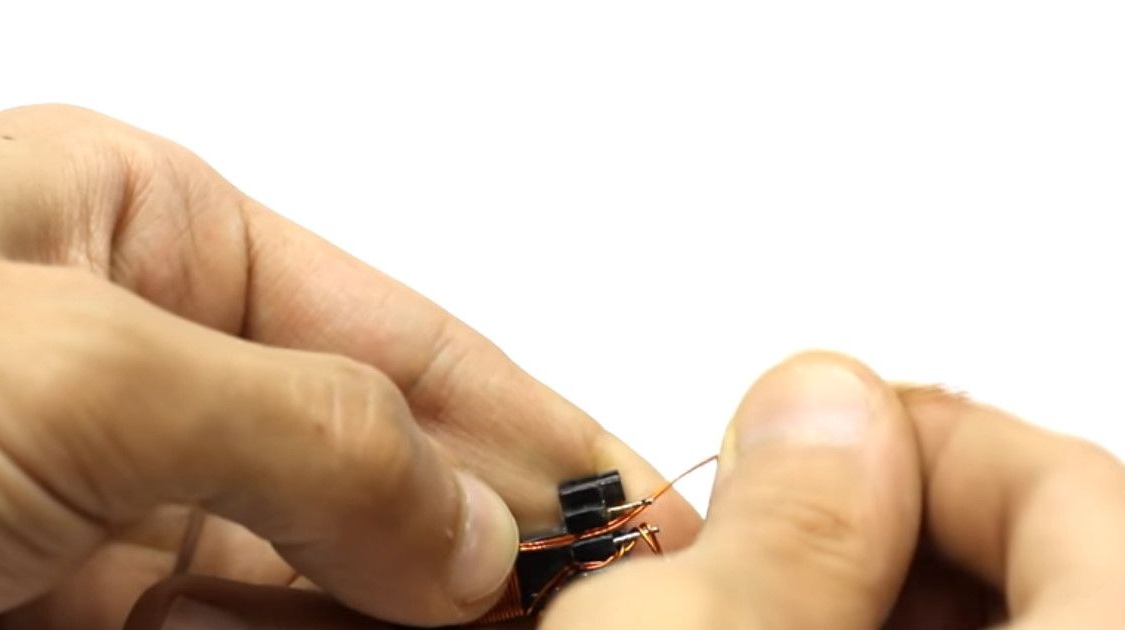
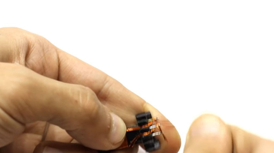
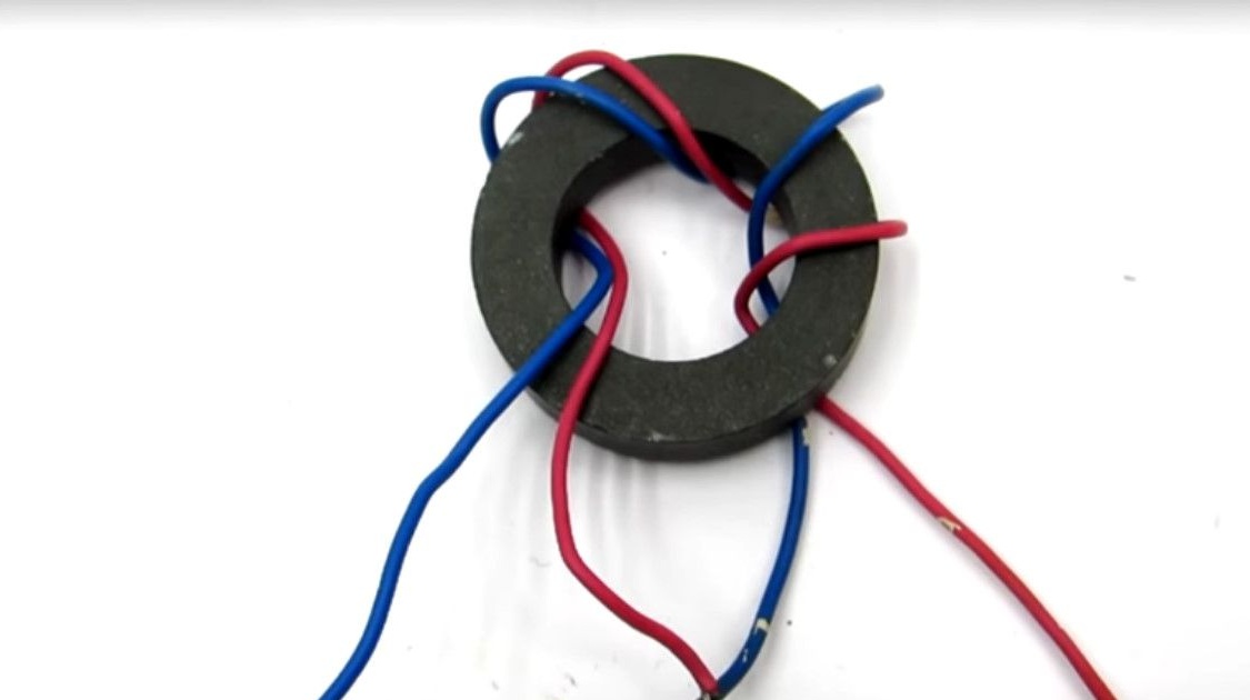
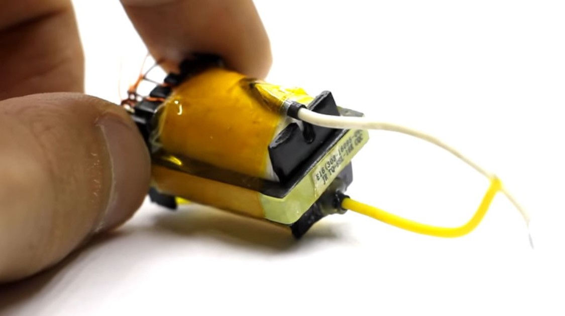
We return to the primary winding.
The primary consists of two separate wires that are wound in parallel.
Phase them to get the midpoint.
The scheme is shown in the photo.
The author spent several hours on winding this transformer. Patience just deserves respect!
For lovers of measurements. The secondary resistance is 320 ohms.
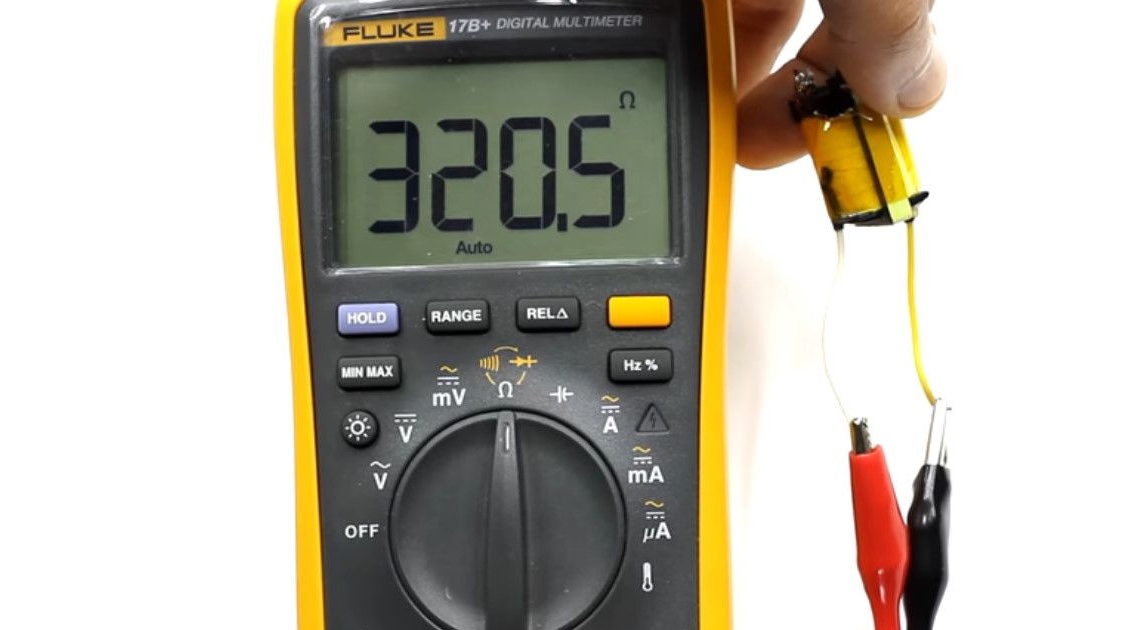
Inductance 139 ml
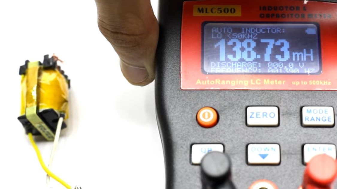
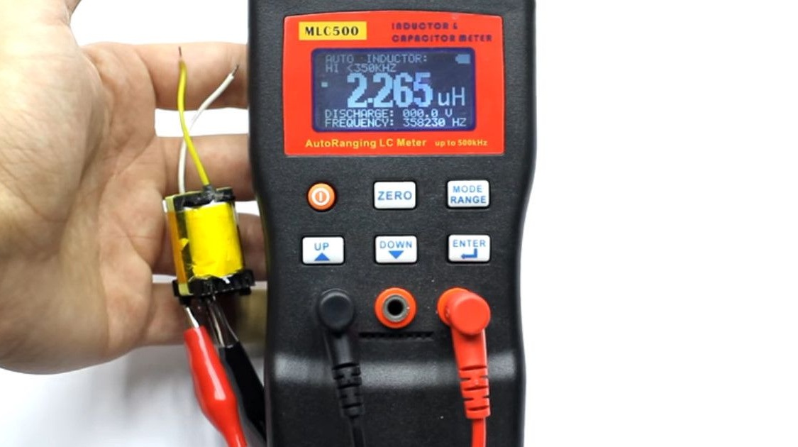
The magnitude of the inductance of the primary winding is 2.27 μH.
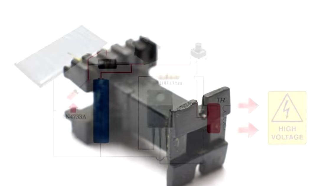
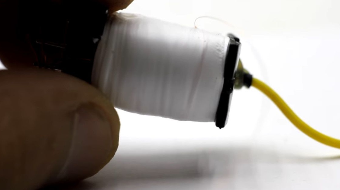
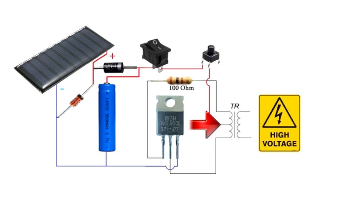
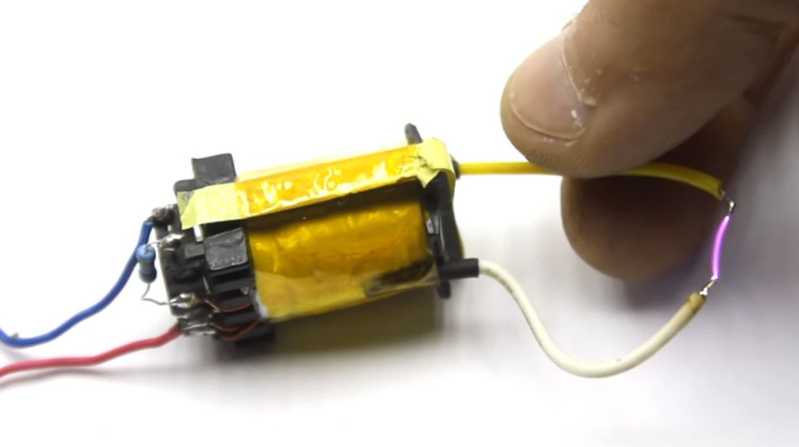
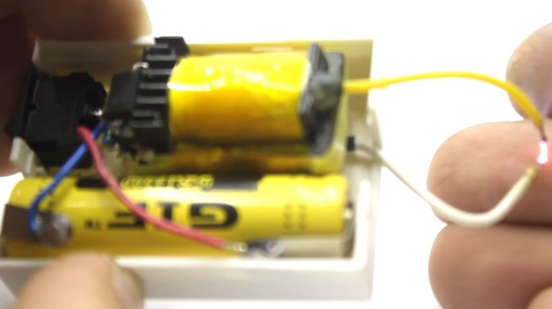
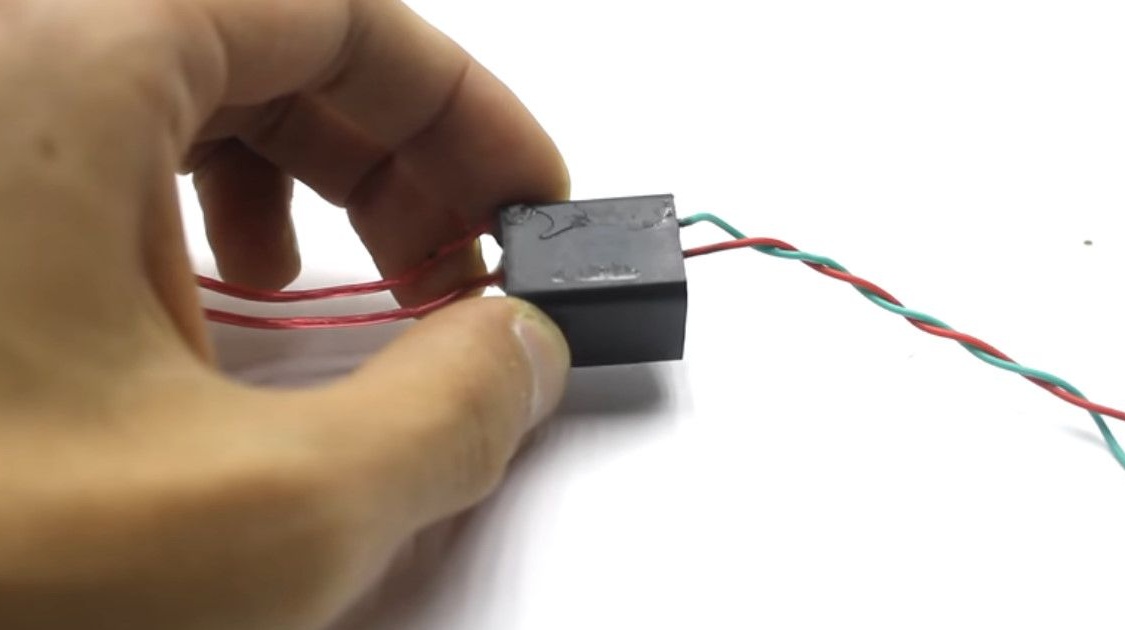
So, 90% of the work is completed. We collect all the cooked items according to the scheme.
Connect the power.
For example, to a 3.7V lithium-ion battery.
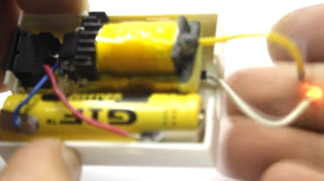
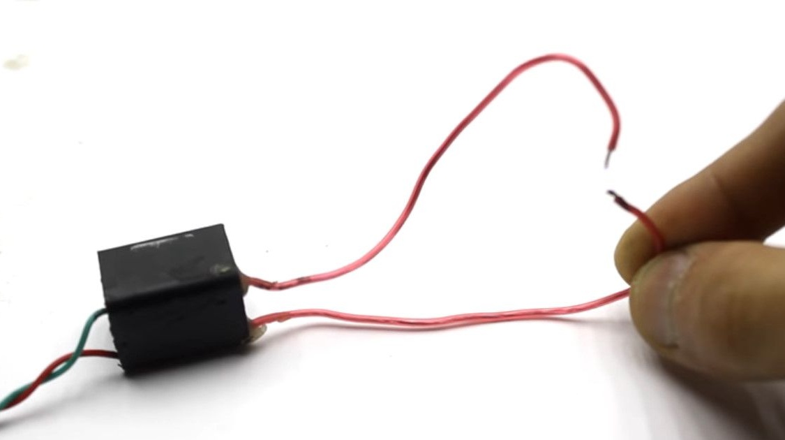
An arc is formed at a distance between the electrodes of 0.5-0.8 mm.
It can be stretched to 1.5 cm.
As the supply voltage increases, the breakdown distance will increase.
If you wound the transformer for the first time, then it’s better not to risk it. In case of breakdown, you will have to repeat everything again.
Now about the rest of the elements of the electronic match.
As a power source, the author wanted to use an ionistor.
The ionistor is a "supercapacitor" with a voltage of 2.7 V. Capacities are different. For example, 100F.
When using field effect transistors with a low operating voltage, the ionistor as a power source came up, but the device worked for only 10 seconds.

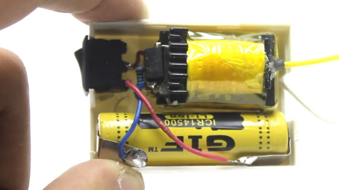
Therefore, a classic 14500 Li-Ion battery was used with the dimensions of a regular finger battery and a voltage of 3.7 volts.
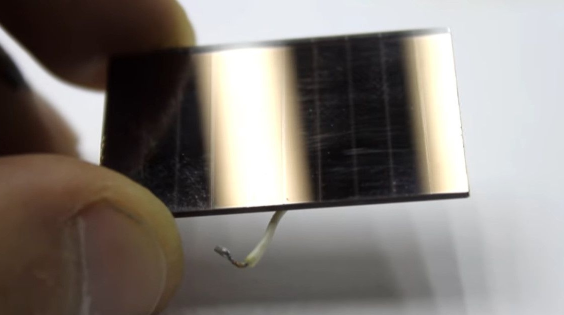
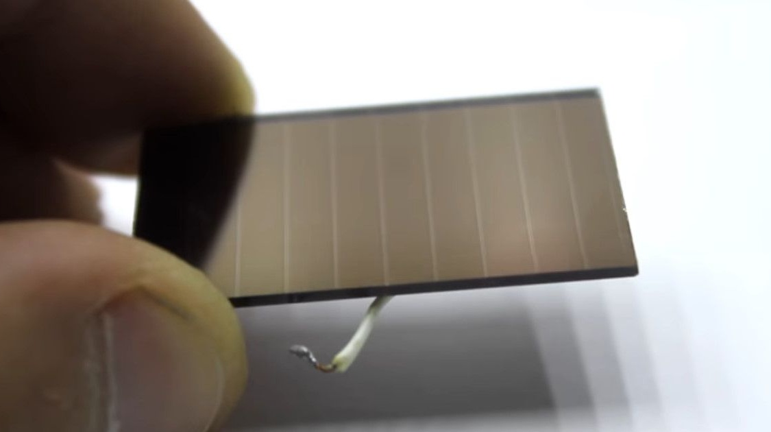
Discharge to the battery never threatens, it will be recharged by a small solar battery made of amorphous silicon.
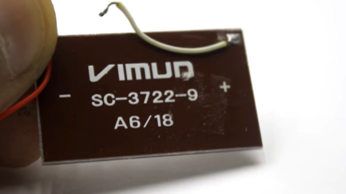
Amorphous silicon, in comparison with single and polycrystalline modules, is capable of generating electricity even at low light levels.The output voltage of the applied battery is 5 volts. With a very small operating current, it is difficult to spoil the battery.
But the author is reinsured and puts the simplest stabilizer.
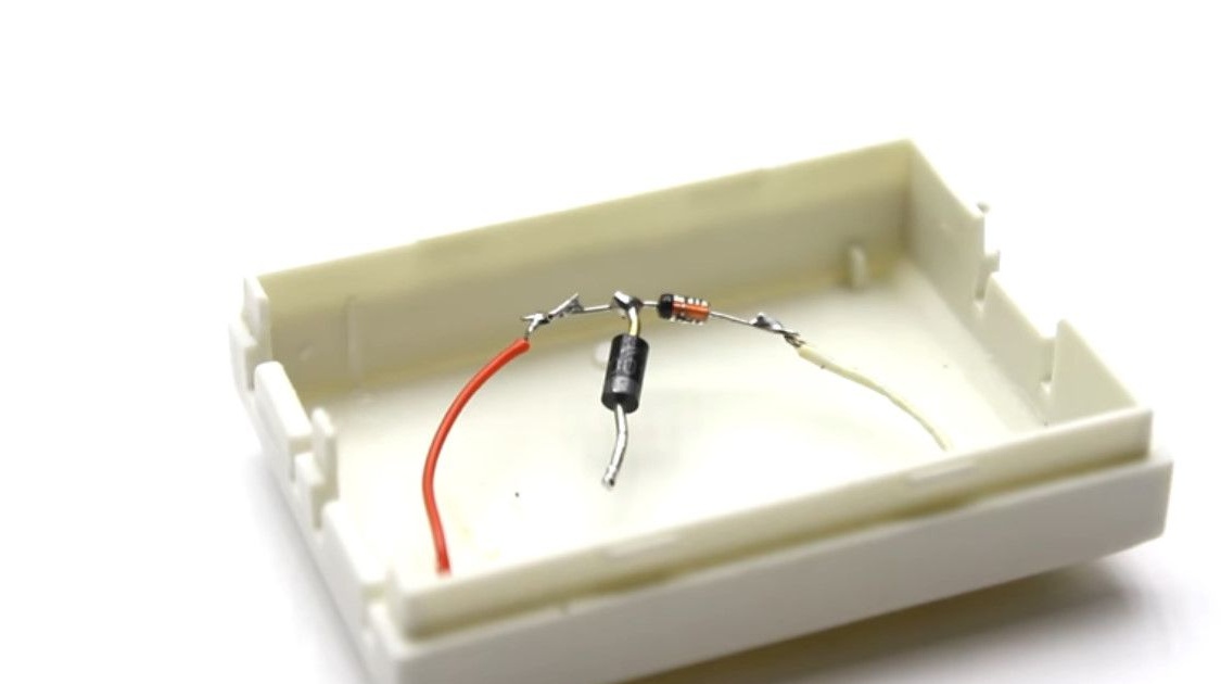
Also, the voltage will drop on a semiconductor diode installed to prevent the voltage from the battery from getting on the solar battery.
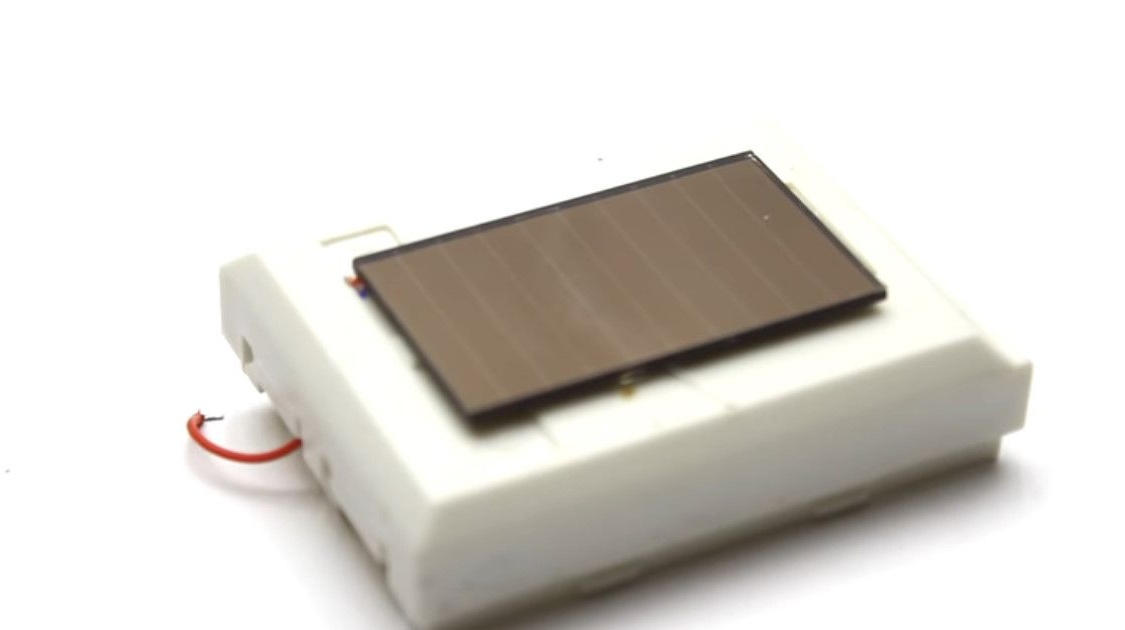
A fragile battery should be protected with something transparent. And fix on the case.
The circuit is switched on by a switch. You can install both the switch and the clock button without locking. So that the circuit itself does not turn on in your pocket.
The author still earned a small burn when shooting. Be careful.
You can certainly purchase a similar converter on Ali.
But to do it yourself - these are additional skills and pleasure!
Homemade introduced AKA KASYAN. Many thanks to him for the work done.
Link to the original video - under the text is the "source" button.