

A tabletop burner is the main glassblower tool, no matter whether it is glass instrument making or the manufacture of funny figures and decors. The burner forms a flame, convenient for softening the glass and subsequent operations with it. In this case, it becomes necessary to obtain various temperatures and forms of the torch.
By chance, I got a small tabletop glass-blowing torch, forming a rather thin unregulated needle of flame. Even when working on gasoline vapors (the flame temperature is higher than that of a gas-air flame), the burner power was not enough to work with however large workpieces. For some increase in the heat flux, two burners were compiled - a gas portable was added, in the opposite direction, or like that.
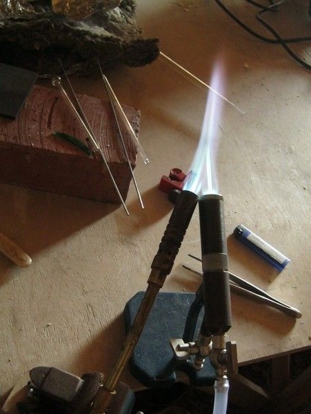
It turned out a fluffy flame, with a high-temperature needle in the center. Things went more fun, it became possible to inflate a 10mm tube. The next logical step was the manufacture of a more powerful burner burning gasoline vapor.
It will be a prototype of the burner made of improvised materials - these are mainly plumbing components. Parts were machined without a metal lathe. The burner runs on gasoline vapors and is based on the glass-blower Yuri Nikolayevich Bondarenko [1], a glass-blower-astronomer manufacturing gas-discharge devices. The solutions of some units were borrowed from its design; otherwise, the burner will repeat the design known to jewelers and dentists.
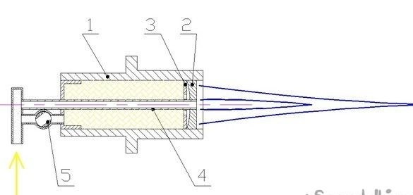
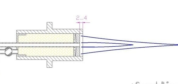
Its base is a hollow cylindrical body 1, coaxially with which the nozzle 4 passes through. The cork faucet 5 allows you to adjust the shape of the torch - when you open it, part of the combustible mixture enters the body in addition to the nozzle and is formed into the torch by grid 2. Aperture 3, coupled with the shape of the grid 2 and the resulting lenticular cavity, concentrates the flow of the combustible mixture mainly along the axis of the burner. These parts are borrowed from the mentor’s burner [1]. On the nozzle tube there are several holes supplying a little gas to the grid (not shown in the sketch) and with a completely closed faucet 5, to form a small supporting torch.It does not allow the main torch to break - the “needle” at high gas flow rates. These holes are selected when setting up the burner.
Tools, equipment.
A soft gas solder needs a small gas burner. Set of bench tools. Electric sharpener. A wood lathe and a drilling machine were used. Vise.
Materials
In addition to the iron pieces, a copper tube of 6 mm diameter was needed. Tin-copper solder No. 3, flux to it. Cork faucet from a samovar.
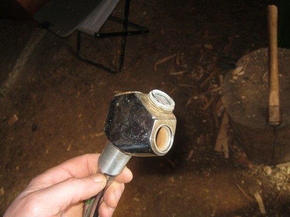
The blank for the burner body was a factory bronze fitting from a plumbing shop with an internal diameter of 30 mm. Several different parts were also purchased there, some of which were also used later as blanks for burner elements.
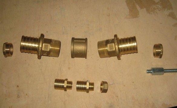
One of the fittings is used as a housing without changes. The fitting was not turned on the outside - the large wall thickness and tides provide the body with additional heat dissipation.
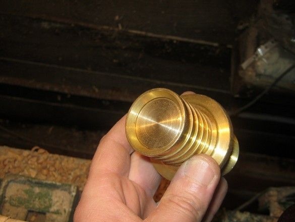
The size of the plumbing plugs was chosen so that with minimal turning of the thread, the resulting part fit into the internal channel of the fitting. I grind wood on a lathe, for this I turned a simple snap on which I planted a workpiece.
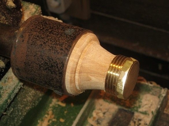
Density of landing allowed more, no way to fix the part. Strongly entering corners of a turnkey hexagon, are previously ground on a grinder. Turnovers - about 1000 rpm, first rough turning with a small “grinder” - the part rotates, the grinder works. After finishing the file and the middle skin pinned onto a wooden block. The end fixing of the workpiece made it possible to conveniently and often try it on to the “place of work” - the resulting part enters the housing tightly with little effort.
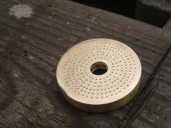
We proceed to the complex and crucial detail - the grid. First, a few theoretical considerations.
The grid, in addition to distributing the combustible gas mixture, is also responsible for safety - they will not allow the flame to penetrate inside and avoid a “back strike”. This is true as our fuel mixture is prepared in balloon "bulb" and not as usual - in the place of the burner. In this type of burner for full-fledged work with glass, including refractory glass, such as Pyrex, the addition of explosive gas from the electrolyzer is necessary.
The flame, passing inside, through the grid, cools so much that it goes out. There is a concept - the ultimate hole. This is the maximum diameter of the “deep” holes that can perform a flame arrestor function, and it is different for different gases. For example, for gasoline vapors in the air, the flame propagation velocity of which is small, the limiting hole is ~ 0.9 ... 1 mm, but as soon as oxygen or explosive gas penetrates the system, which significantly increase the flame propagation velocity, the holes in the protective “mesh” will have to be made substantially smaller. The maximum diameter of the holes, for example, for clean explosive gas, ~ 0.3 mm, which represents some difficulty in the manufacture and operation.
As a kind of compromise, Yuri Nikolayevich proposes to use holes in the 0.8mm grid, while the necessary safety measure in the workshop will be a fairly robust design of the “bulb” and “flushing” of the electrolyzer [1], so that they can survive a possible blast without damage. The gasoline carburetor is made from a propane cylinder, washing the electrolyzer from carbon dioxide fire extinguishers. During normal operation of the equipment, no jumps occur. In case of violations of normal operating conditions, a clap occurs that does not lead to an accident.
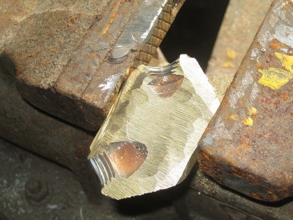
The "length" of the mesh holes, gives its thickness. Given the lenticular shape, the thickness of the mesh should be 3 ... 4mm in the thin part and 6 ... 7mm at the edges. There was no finished plate of such thickness; I had to look for a donor. It turned out to be a rather massive, outdated faucet for the bathroom. A relatively even piece of the wall was cut from it, from which it was possible to cut a blank for the grid.
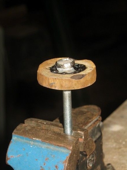
The workpiece, after rough turning, was mounted (soldered) on the M5 screw, for which the workpiece could be secured in a three-jaw chuck for adjusting the size and shape.
Drilling machine, for ease of operation was laid on its side. The concave surface in the workpiece was carved roughly - with a small “grinder”, a “remnant” of the disk (less radius), then brought with a grinding sand. The screw is soldered, so the protruding head was grinded along with the workpiece. After, the external diameter of the workpiece was brought to the desired. After turning, I melted the shank from the workpiece - the remainder of the M5 screw. The remaining hole was drilled to the desired 6mm.
The next responsible and rather dreary stage is to tilt the centers of future holes and drill them. With the right number of holes and their diameter, the task is not easy. The amateur radio experience helped a lot - punching and drilling a large number of holes on the workpieces of printed circuit boards, before the invention of lead-free (SMD) components, was common practice.
The diameter of the holes has already been discussed, it should be said about their number - their total area should be at least 20% of the grid area.
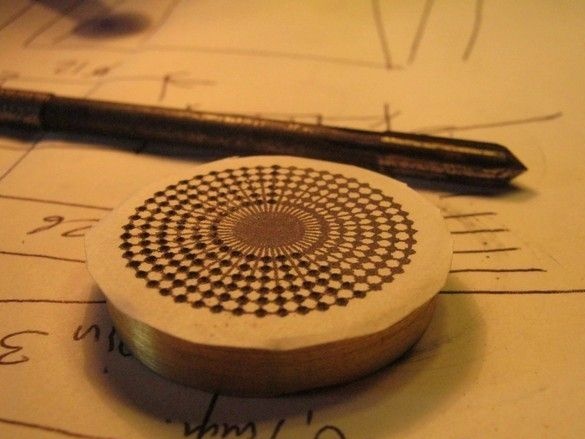
It is convenient to draw holes in AutoCAD, among other things, this program allows you to print a sketch exactly on a 1: 1 scale. After printing, the resulting template was glued to a flat surface of the grid with glue-pencil, focusing on the central hole, it is convenient to do this in the light.
For screwing, I used a special miniature core. You should take care of a good bright light, a special visor with magnifying glasses is convenient for this work. The work is not fast and it is important to organize a comfortable place - some free surface, the "operator" in a sitting position. I recommend doing such operations in more than one approach. After punching, the template peels off, the residues are washed off with warm water.
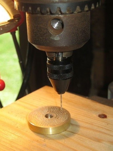
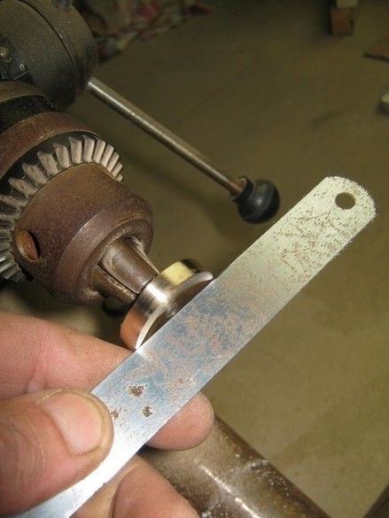
For drilling of this kind - thick metal, thin drills, the necessary accuracy, a variety of handheld devices are completely inapplicable. You should use something more stationary. In this case, a miniature chuck was used to clamp my 0.8mm drill; the chuck shank was clamped in a large three-jaw chuck on a bench drill. This combination allowed us to confidently drill with a thin drill; I broke only one, and even then at the very end.
I turned out to be inexpensive drills purchased in a radio store and they were of poor quality, a kind of simplification from the idea of a drill. The grooves for chip discharge on them were very shallow. There is a suspicion that they are made specifically for drilling foil fiberglass and it is better to use normal "machine-building" drills.
Yuri Nikolayevich says that there are instances of drills that jam during deep drilling, so you should buy them with a margin and then choose not wedges. There is an assumption that this is due to their taper. Drilling is somewhat easier when lubricating the drill with oil or alcohol, but alcohol must be constantly added.
The correct sharpening of such a miniature drill is a difficult task and in the absence of skill, it is better to use new drills, otherwise, a significant "pull" is inevitable when drilling. However, with careful drilling in the machine, all the necessary holes can be drilled with one drill from one sharpening.
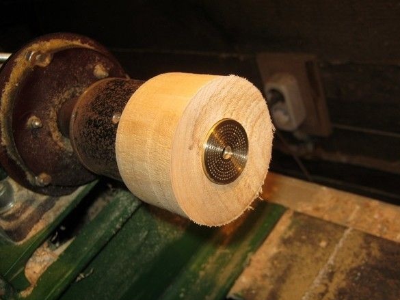
After drilling, all resulting small burrs should be sanded. This is most conveniently done on a rotating part. To install the grid in a wood lathe, the simplest equipment was machined. The mesh fits snugly into the recess.
In the manufacture of the prototype burner, it was supposed to work only on gasoline vapors, so some of the holes were made larger - 1mm.
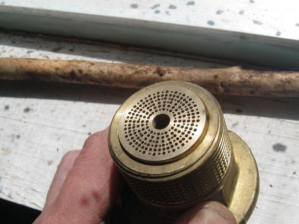
The grid is recessed into the body by 2 ... 4mm. Yuri Nikolaevich, recommends that this size be carefully chosen - if there is an excess, the burner body will heat up very much, if it is insufficient, the torch in some modes is prone to breakdown.
In my "low-temperature" case - when feeding only gasoline vapors, without explosive gas and with a very massive case, I set the maximum depth without adjustment. After, it would be nice to solder the mesh. This should be done with “hard” solder. Copper-phosphorus is suitable, but in this case, silver solder like PSR-45 is better, it burns out less. I couldn’t fully solder the mesh into my massive case, I could not solder it with solder - there was not enough temperature, even when I warmed it with a reflector, a large blowtorch. However, the grid entered the body with a good fit, so I left it as it is.
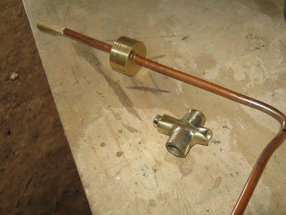
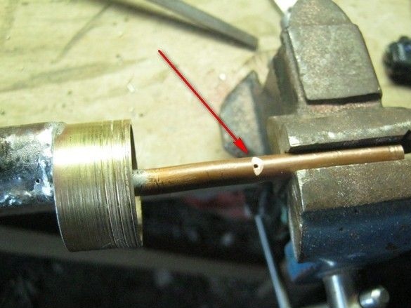
Nozzle - a complete simplification. Made of copper tube with an inner diameter of 4mm. Use only as a trial option. I will quote from [1] - “The nozzle should give a narrow laminar flow of the combustible mixture and a sharp torch at least with a low flame. Its laminarity can be ensured with a hole diameter of up to 2.5 mm, a length of more than 35 mm, a polished inner surface and a calm flow at the inlet. The laminar flame makes less noise and allows you to reduce the heating zone, so you should try to get a laminar torch. (Professional glassblowers may have different opinions on this subject). The nozzle opening is best made conical - this will provide less resistance to flow. The end part with a length of about ten millimeters should be made cylindrical. "
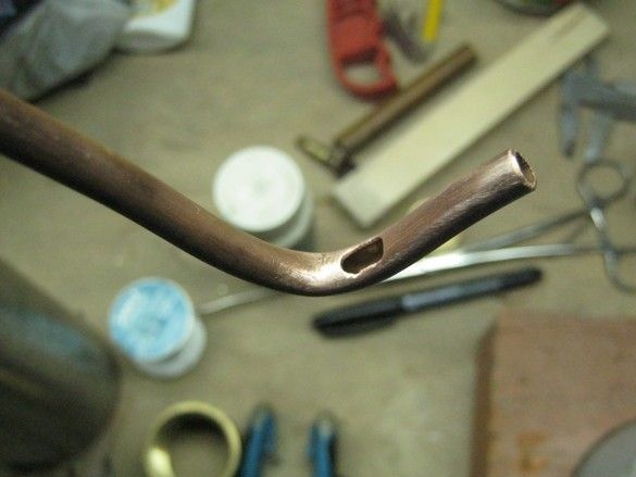
Before bending, the nozzle tube was annealed and filled with dry sand. The inner cavity of the burner was loosely filled without special fanaticism with a copper “muddle” - this is additional protection against the “breakthrough” of the flame and calming the gas flow. The padding also holds the diaphragm pressed from the inside to the grid.
All soldering “behind” is made by tin-copper solder, with a melting point of about 200 ° C. The burner body heats up significantly, the tail part is not higher than 60 ° C - you can easily grab it by hand and even after prolonged use the unit does not collapse.
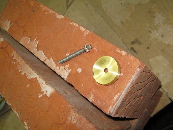
The diaphragm itself is made of a flat 3mm brass plate. For a more pronounced effect, the “lens” should be made biconvex, for which the diaphragm should also be concave. To do this, it can be bent using Punzel and Anki, or grind from a thicker workpiece similar to a grid.
After trial ignitions, it seemed that the torch was short, as a probable reason, thin sections of tubes supplying gas to the casing were seen. The burner has been upgraded - the cork tap channels are drilled to a diameter of 7mm, the common supply tube has been replaced.
It got a little better. At the same time, I set up a supporting torch. Yuri Nikolayevich advises to file a triangular file of grooves, a kind of asterisk of five to seven rays, in the hole in the mesh through which the central nozzle passes, so that there is an enhanced mixture flow around the nozzle. It will increase the stability of the "needle" and reduce stall in turbulent mode.
The amount of combustible mixture for the supporting flame is set by the holes on the nozzle inside the housing. Their number and size are customizable.
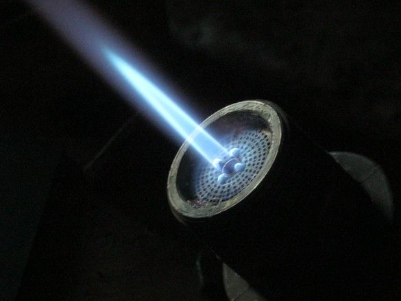
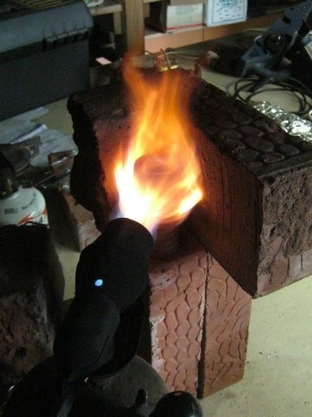
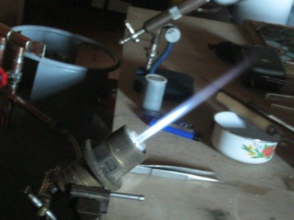
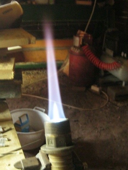
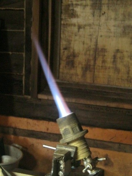
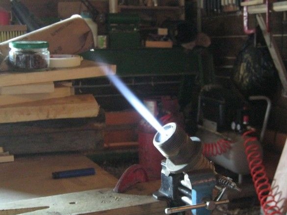
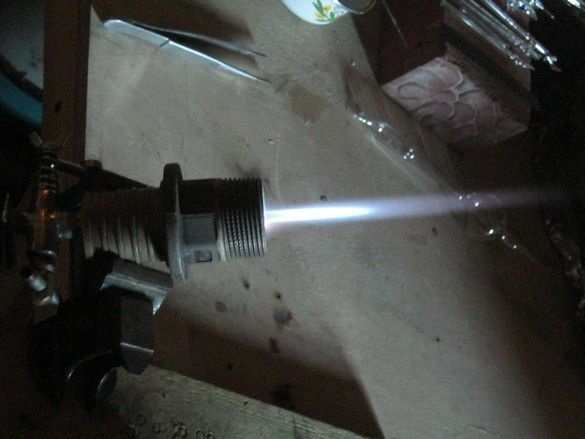
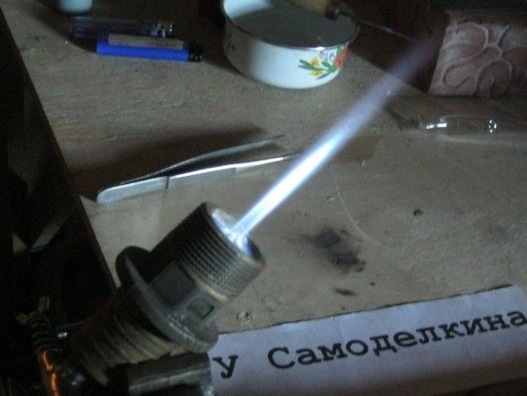
A few photos of the torch obtained to date with a different position of the faucet on the burner - so to speak, “needle”, “soft” flame and something average.
A “leg” for the experimental burner was not made; during operation, it clamped its case in a small table vise.
The resulting torch is much larger than the first small burner, even with the addition of a gas sister. The glass heats up much faster and a larger area, "flows", it was possible to inflate an 18mm tube from fusible "neon" glass. It turns out operations that did not succeed earlier - turning the edges, piercing a thick layer of glass with a tungsten needle.At the same time, the need to further increase the temperature of the torch is felt. There are not many options - the addition of oxygen or explosive gas.
Work on the bugs. Ways of further improvement.
Nevertheless, this kind of work should be done using a metal lathe, parts and the whole structure will be more accurate and accurate, making them less painful. The diameter of the casing and nozzle is obviously too big, it seems that is what does not allow to get a longer torch of soft flame - the gas velocity when falling into a wide casing (nozzle) drops significantly. It is worth approaching the size of the burner in [1]. It would be nice to make a nozzle, a body, a mesh and a diaphragm from a brass blank, and not from anything - the design can be made more convenient in assembly and adjustment. It would be nice to make a nozzle according to the charter - a chiseled, conical polished hole (see above, or [1]). About oxygen or "rattlesnake", already said.
Literature.
1. Bondarenko Yu.N. Laboratory technology. Production of gas discharge light sources
for laboratory purposes and much more.