» Electronics »MEGAOMMETR at Atmega328R

MEGAOMMETER on Atmega328R

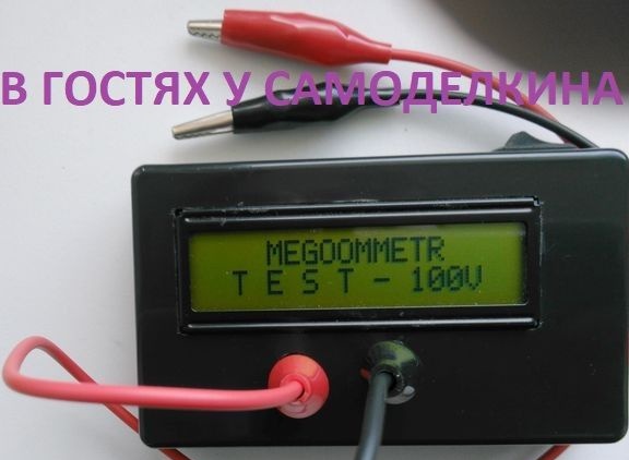
COMPACT LEAKAGE METER
MEGAOMMETER AT Atmega328R


MEGAOMMETER on Atmega328R


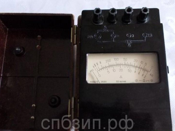
The industrial version of the megohmmeter is quite large and has considerable weight. The only advantage of this monster is that it is trusted, but if you need to urgently measure the leakage resistance in the repair, then electronic option is more preferable.


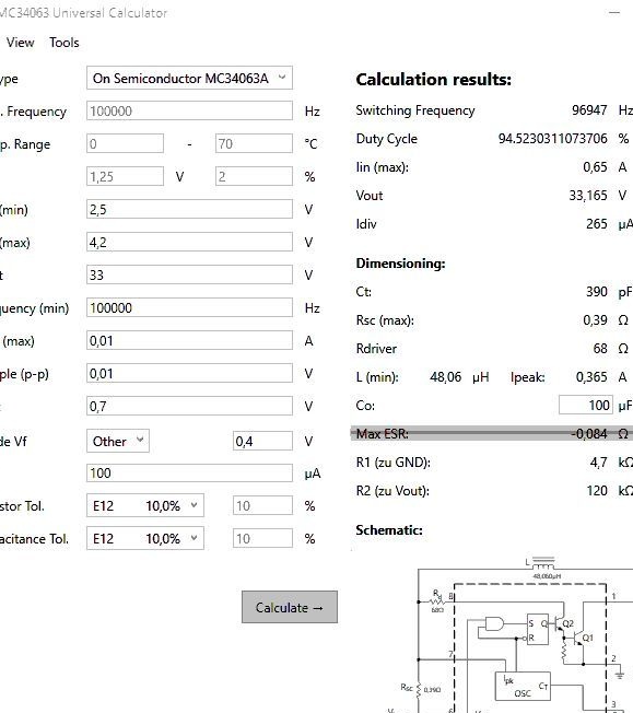
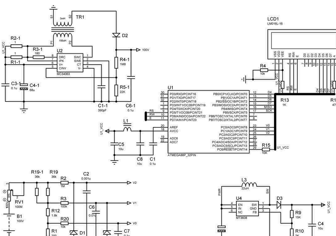
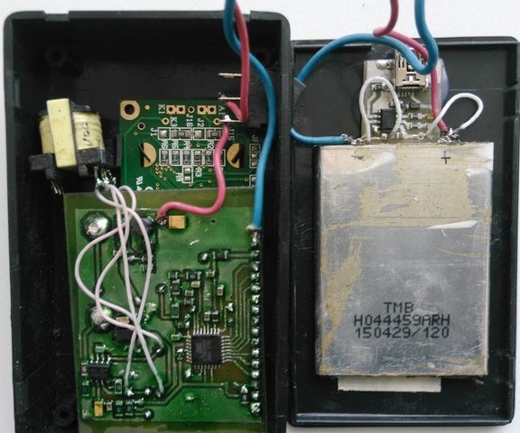
Searching on the Internet, I did not find a simple device, the only megohmmeter that radio amateurs repeated was from Silicon Chip magazine in October 2009, but with improved firmware. The device offered to your attention has dimensions 100x60x25 (were purchased on AliExpress) and has a weight of not more than 100 grams. The device is assembled on an Atmega328P microcontroller. The power is supplied by a lithium battery and the current consumption is about 5 mA. The lower the resistance of the measured circuit, the greater the current consumption and reaches 700-800 mA, but it must be taken into account that circuits with resistance less than 10 kOhm are rare and the measurement is carried out in a few seconds. The device uses two DC-DC converters on MT3608 and MC34063. The first is used to power the controller, the battery voltage rises and stabilizes at 5 volts, the second is a 100V converter, this is determined by the fact that it is mainly used to measure leakage in electronic devices, and making a 500 or 1000V economical converter is very problematic. At first there was an idea to assemble both converters on MT3608, but after I burned 8 microcircuits, it was decided to do on the MC34063. And at 500, 1000V, a higher impedance divider had to be used, and as a result, the use of Rail-To-Rail operational amplifiers.

Indication is carried out on the liquid crystal display. To charge the battery, the charge controller on TP4056 is used (a separate scarf 17x20 mm).


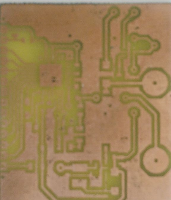
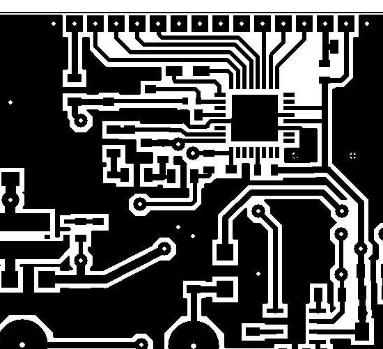
The device is assembled on a double-sided printed circuit board made of foil fiberglass made using LUT technology. Do not be afraid of the word “double-sided.” Two PP bottom and top images are printed (mirrored). Combined into the gap and fastened with a stapler in the form of an envelope. The workpiece is inserted and first heated with an iron on both sides, then it is carefully ironed on both sides through two standing writing papers. Throw the printed blank into a container of warm water for about half an hour, then use your finger to remove the remaining paper under a stream of warm water. After etching, we tin in the Rose alloy. The through holes for the conductors are made of tinned copper wire with a diameter of 0.7 mm. The inputs of the device are made of brass tubes from an old multimeter, so you can use standard probes from multimeters, but it is advisable to make home-made ones with crocodile clips.


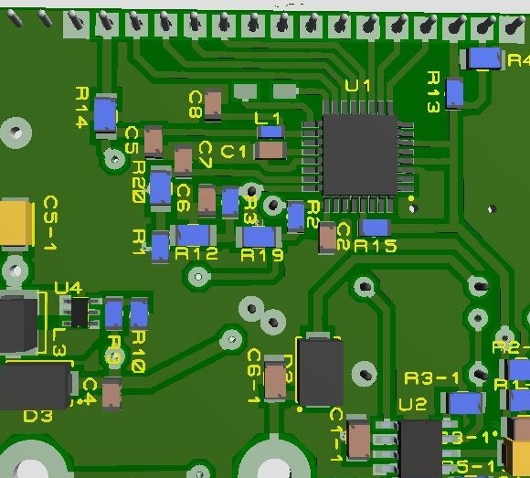
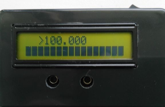
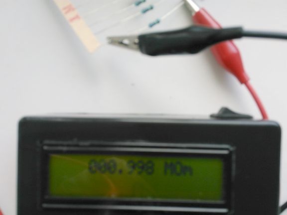
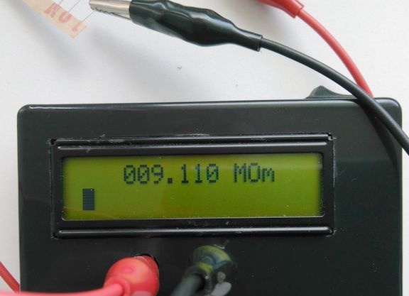
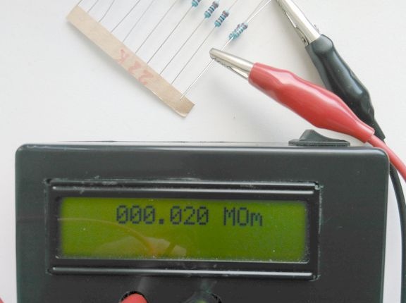
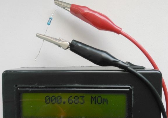
Applied SMD parts, resistors 5%, capacitors 10%. It should be noted that this is not an ohmmeter and does not serve to accurately measure resistance, although the accuracy in the range of 1K - 1M is quite large. To increase the reliability of the readings, the entire range of resistance measurements is divided into three. The firmware used oversampling. Three voltage dividers 1; 10, 1: 100 and 1: 1000 are used. The last range is very stretched, from 10 mOhm to 100 mOhm and with a 10-bit microcontroller ADC resolution, it has a very large step, about 90 kOhm. In addition, it was necessary to apply the protection circuit with the input of the microcontroller and they introduce an error on the upper two ranges. Below you see pictures with the results of measurements.


Maybe someone wants to improve the device or more accurately calibrate, so I apply the source. When calibrating, we connect an accurate resistor no worse than 1%, for example 47 kOhm and select a coefficient for the range of 10-100 kOhm in the line:

if ((volt1 <1000) && (volt1> volt0))
        {
          amper = volt1 / 1800.0; // uA
          volt = 100000.0 - volt1;
          if (amper! = 0) om = (volt / amper - 1800.0) * 1.1235; // a multiplier is selected.
        } else


The scale from 10 to 100 mOhm is very non-linear, at the beginning the readings are underestimated by kx2, and at the end of the range they are overestimated by kx1, so two factors are selected similarly, but we put the resistor at 20 mOhm, then 47 mOhm and then 91 mOhm:

        
#define kx1 -0.145
#define kx2 0.8

............

        if ((volt2 <1000) && (volt2> volt1))
        {
          volt = 100000.0 - volt2; // on Rx
          amper = volt2 / 18000.0;
          if (amper! = 0) om = volt / amper;
          om = (om + om * (((1000.0 - volt2) /1000.0) * kx1 + volt2 / 1000.0 * kx2));

9
6.8
7

Add a comment

    • smilesmilesxaxaokdontknowyahoonea
      bossscratchfoolyesyes-yesaggressivesecret
      sorrydancedance2dance3pardonhelpdrinks
      stopfriendsgoodgoodgoodwhistleswoontongue
      smokeclappingcraydeclarederisivedon-t_mentiondownload
      heatirefullaugh1mdameetingmoskingnegative
      not_ipopcornpunishreadscarescaressearch
      tauntthank_youthisto_clueumnikacuteagree
      badbeeeblack_eyeblum3blushboastboredom
      censoredpleasantrysecret2threatenvictoryyusun_bespectacled
      shokrespektlolprevedwelcomekrutoyya_za
      ya_dobryihelperne_huliganne_othodifludbanclose
27 comments
Vls
good afternoon
there is a desire to repeat the device
have questions. 328 or 88 controller. need firmware and fusion file.
Regards VLS
Author
Quote: Ivan_Pokhmelev
And what kind of beast is this "eco -izer"?

I really don’t know, but the thing is very accurate and everything is in Feng Shui, in the sense of GOST. Sorry, I’ll be silent for a couple of days, I'm collecting my first 3D printer, I received it yesterday AliExpress. This is not an advertisement!
Quote: IOPA4
Are we discussing a homemade product or a device for an eco -izer?

And what kind of beast is this "eco -izer"?
Quote: IOPA4
Are we discussing a homemade product or a device for an eco -izer? You probably lack communication. I wrote to you in detail, I'm going on a “business trip”, I need to take a tool.

Those. as help to you and possible repeaters, you do not perceive this discussion ("criticism"). And we twisted the handle of the megger ... when rejecting powerful thyristors. Inconvenient crap and inaccurate
Quote: IOPA4
Short circuit, checked circuit. Short there, and you put this device. All 100 V and will be at the input.

And these 100 V will be connected to the divider described in detail to you through RV1 = 100 MΩ, at least as shown in your diagram. Or again "here we play, here we do not play, here I wrapped the fish"?
And one more thing: a photo of a printed circuit board without details - some kind of "left", not directly related to the device in question.
Author
Quote: Ivan_Pokhmelev
It depends. )))

Megalomania?
Author
Quote: Ivan_Pokhmelev
Where is the short circuit inside the device?

Short circuit, checked circuit. Short there, and you put this device. All 100 V and will be at the input. Zener diodes in protection at 4.7V.
Author
Quote: Pronin
GOST

Are we discussing a homemade product or a device for an eco -izer? You probably lack communication. I wrote to you in detail, I'm going on a “business trip”, I need to take a tool. If everything is uploaded according to GOST, they will not let me on the plane, but I need to work. I take a True RMA multimeter and this self-made tester, a couple of screwdrivers and keys. I know that less than 1 megohm is bad, and even if it shows 1.000001 megohms on a super megameter megameter, I’ll think about the reason anyway. Yes, a trivial question, did you spin the megger? What are the hundredths and tenths, the arrow sausages from side to side. And about GOST, write to Labcenter Electronics, maybe they will change the numbering and designations as it suits you. And in short: there is GOST, but there is life. Remember when you did MOT at home, checking the insulation of the cable, did you mark the switches, pipes, do you hang up signs, etc. etc. I’ve had 1.5 squares in the Admiral’s house “lyumishka” since 1975, and you are talking about GOST.
The PWR (+ battery) mark is made in order to create a polygon on the printed circuit board, which automatically merges with all the conductors and outputs of the elements that have the same label.

It is clear that GOST designations (GOST 2.728-74 eskd) are not familiar to you. Therefore, the incidents in the diagram. In the Proteus simulator, elements and relationships can be behind the scenes.
And the capacitor C5-1 is stuck electrolytic (polar). For the simulator no matter what you put. And for a real circuit, for example, 10 μF x 10V
In addition, it was necessary to apply the protection circuit with the input of the microcontroller and they introduce an error on the upper two ranges
What are your zener diodes? If they are significant, why didn’t they use less leakage protection?
Where is the short circuit inside the device? But what are you talking about short-circuit wires from the battery do not say - there will be even more current. )))
And about the "old capacitor" I did not write anything.
By the way, it’s time for you, as a radio amateur with 40 years of experience, to learn that microfarads are designated “microfarads”.
I didn’t have a question about PWR at all, but you are trying hard to answer me. And about 5 other signals, keep silence just as persistently. )))
Author
Quote: Ivan_Pokhmelev
With PWR, let's say everything is clear, but I was not asking about this signal. )))

The PWR (+ battery) mark is made in order to create a polygon on the printed circuit board, which automatically merges with all the conductors and outputs of the elements that have the same label. Made in order to improve the cooling of the MT3608 (SOT23-6 housing) through the power leads, the same thing was done with GND. The Proteus program has good topic.
Author
Quote: Ivan_Pokhmelev
About 100 megohms in series with them, we modestly keep silent?

You probably have not read about KZ. Sorry, but you seem to be a writer, not a reader. "Antique 10M capacitor" - 10u means "newest" 10 mkF.
Quote: IOPA4
What kind of bullshit are you writing about? "Rated output voltage from 90 to 110V" - are you talking about this?
It is not said that he is two-limit.
And this is not bullshit ?!


Quote: IOPA4
Still wondering about the current divider. Ohm's law. 200 + 1.8k + 18k = 20k. 100V / 20kOhm = 5 mA, 100V * 5mA = 0.5W, and this is ~ 150 mA from the battery without taking into account efficiency and conversion up.
About 100 megohms in series with them, we modestly keep silent? )))

Quote: IOPA4
And at the expense of the accuracy of the "pointer", the photo shows that the error is not more than 5%,
The error cannot be determined from the photo.)) Even if you really have 5%, then this is not a meter. Learn the materiel!

Quote: IOPA4
I didn’t ask myself with particular accuracy and used 5% resistors, if you conjure, then you can achieve better parameters, except for the range of 10 MOhm - 100 MOhm.
When using such resistors, even with their selection and software adjustment, it is difficult to obtain normal accuracy without periodic calibration from a reference source.

Quote: IOPA4
P.S.In CAD, it is accepted that conductors have the same potential if they have the same label (this is one circuit), so with PWR (power) everything is clear.
With PWR, let's say everything is clear, but I was not asking about this signal. )))

Quote: IOPA4
I do not think that the program is smarter than a person
It depends. )))
< P.S. В САПР принято, что проводники имеют одинаковый потенциал, если они имеют одноименные метки (это одна цепь), так что с PWR (power) все понятно. Не думаю, что программа умнее человека (Proteus 7.10), но она с легкостью решила этот "кроссворд". >
Those. you suggest looking for your circuits and conventions in a circuit using a program (Proteus 7.10). Original good But, I do not have Proteus 7.10 (Spanish. Others). And according to your innovation (it’s fashionable), cool Yandex has found 74 million. PWR tags. And you need 2 on your circuit.
And some old capacitors are marked C5-1 (10m). And there is also HTML, and there will probably be C5 // 1 scratch
Author
What kind of bullshit are you writing about? "Rated output voltage from 90 to 110V" - are you talking about this? So I wrote a 100-volt. Too lazy to look for "your" passport. Still wondering about the current divider. Ohm's law. 200 + 1.8k + 18k = 20k. 100V / 20kOhm = 5 mA, 100V * 5mA = 0.5W, and this is ~ 150 mA from the battery without taking into account efficiency and conversion up. And at the expense of the accuracy of the "pointer", the photo shows that the error is not more than 5%, when measuring the leak this is enough with the head. I didn’t ask myself with particular accuracy and used 5% resistors, if you conjure, then you can achieve better parameters, except for the range of 10 MOhm - 100 MOhm. Note that industrial with its "terrible" price and dimensions guarantees accuracy of up to 20 megohms.

P.S. In CAD, it is accepted that conductors have the same potential if they have the same label (this is one circuit), so with PWR (power) everything is clear. I do not think that the program is smarter than a person (Proteus 7.10), but it easily solved this crossword puzzle.
Quote: IOPA4
Industrial megaohmmeter M4100 / 1 at 100 volts.

I looked at the link you indicated, there the bullshit in the parameters is complete.
Quote: IOPA4
This device is a meter, although with a large error on large scales.

Read the regulatory documentation, and then approve. This is an indicator.
Quote: IOPA4
at 2V and the battery will not kill,
Kill, not the first time, but kill. They would have put DW01, and they did not know grief.
Quote: IOPA4
Industrial megaohmmeter M4100 / 1 at 100 volts.
Thanks for the information!
Quote: IOPA4
Set the output, assign a name where this circuit should connect, put the input and assign the same name.
Well, where is the second end of the chains I have listed?
< Наверное вы слышали, что есть шины и нумерация проводов (метки связи). Не обязательно тащить проводник и шину от блока к блоку (от устройства к устройству, от элемента к элементу) через всю схему, что нарушает восприятие и читаемость схемы (загромождение). В САПР это повсеместно используется.>
Excuse me, but your circuitry is more like a rebus than a principle.
I understand the scheme of partial modeling, simulation (for wiring purposes, etc.)
And so on the principle. The scheme of confusion of designations, etc. The node has no input voltage, but there is output voltage. scratch
So guess where the chain goes from the throttle on the PWR line. And where is the beginning and where is the end?
This is not a scheme to sell, Imho. And the application does not configure repetition (verification).
Author
Probably you understand the difference between an indicator and a meter? For example, a device on “neonka” or “squeaker” is an indicator, and this device is a meter, although with a large error on large scales. I wrote about this. Industrial megohmmeter M4100 / 1 at 100 volts. The information content of the display 1602 is not very conducive to the conclusion of information about the battery, although this cannot be done, for example, during the start of the device. For myself, I decided that the MT3608 starts at minimum at 2V and the battery will not kill, well, you can additionally check the voltage with a multimeter once a month.
Well, on the "mistakes" in the diagram, which, as you think, are in the diagram. You've probably heard that there are buses and wire numbers (communication marks). It is not necessary to drag the conductor and bus from block to block (from device to device, from element to element) through the entire circuit, which violates the perception and readability of the circuit (clutter). In CAD, this is commonly used. Also used are the terminals input, output, ground, power, ..... Set the output, assign a name where this circuit should connect, put the input and assign the same name. In the diagram RS, RW, E, V0, V1, V2, GND, U1_VCC and ..... Everything is very simple to disgrace, everything is thought up to me.
Structurally, the transformer is not very well located, but I could not find the ferrite core to fit in the gap between the two boards, the indicator and the main MK board. Maybe the board is slightly divorced not successfully, but the conductors are very short and there are no pickups. The power supply of the analog part is supplied through a choke with a filtering capacitor. The second side of the board is almost continuous and at minus power (GND). In addition, filtering by the input of the ADC is applied both on the elements and programmatically, so there are no jitter indications. The case used the factory and there were no other options for fastening.
Quote: IOPA4
1. Who would argue? In such a wide range, make a meter on a 10-bit ADC.
So it should be called "Indicator", and not "Megaohmmeter" or "Meter".
Quote: IOPA4
2. We use 100-volt for checking equipment and 500-volt for checking cable routes, if they are not connected to the equipment.
And what is a 100-volt (name)?
Quote: IOPA4
3,5. Even at 100 volts (short circuit), the divider current is 5 mA, i.e. 0.5 watts
It is unclear what you mean. ((What divider current? Where does 5 mA come from? Why Rail-To-Rail?
Quote: IOPA4
4. SMD stovoltovye.
So, for 100 V, you need to take 2, for 500 V - 6 pieces.
Quote: IOPA4
6. The diagram is drawn in the Proteus (Isis) program, it is perfectly simulated and the program does not see errors. With a bunch of blunders, it would fall out of the simulation with a bunch of bugs and warnings.
Quote: IOPA4
You were probably confused by a 100 volt battery and a variable resistor.
Not only this. Electrolytes are designated as non-polar capacitors. The battery power is not displayed, the presence of a switch. It is not clear where the signals MISO, SCK, V0, V1, V2 go.
Quote: IOPA4
7. The charge control is carried out by TP4056, it is written in the text.
I repeat once again: there is no protection against overdischarge.
Quote: IOPA4
8. Strange, but why does it work? But when changing the phasing of the windings it does not work.
Do you understand the meaning of the word "constructively"? Since the trance is located at some distance, to reduce interference, its input and output signals should be fed in twisted pairs, and also not to drag the connection point of the trans output to D2 to the connection point of output 1 of the U2 chip.
Quote: IOPA4
9. Units of measurement took from here.
You, probably, looked poorly: everything is correctly written on your link, and not like yours.
Author
You were probably confused by a 100 volt battery and a variable resistor. This is just for simulation. Because Proteus is very difficult to simulate analog models, in about 3-5 minutes the circuit on the MC34063 goes to 100 volts at 100% processor load and only after 5-10 minutes the LCD appears on the LCD, I had to turn off the chip simulation after I checked the 100-volt converter . Further simulated only the work of MK and indicator. The circuit and board in this program are tightly coupled, and for any mistakes, the printed circuit board would have turned out to be bloopers and not working, and contrary to your comments, it would work immediately after the firmware.
Author
1. Who would argue? In such a wide range, make a meter on a 10-bit ADC.
2. We use 100-volt for checking equipment and 500-volt for checking cable routes, if they are not connected to the equipment.
3,5. Even at 100 volts (short circuit), the divider current is 5 mA, i.e. 0.5 watts
4. SMD stovoltovye.
6. The diagram is drawn in the Proteus (Isis) program, it is perfectly simulated and the program does not see errors. With a bunch of blunders, it would fall out of the simulation with a bunch of bugs and warnings.
7. The charge control is carried out by TP4056, it is written in the text.
8. Strange, but why does it work? But when changing the phasing of the windings it does not work.
9. Units of measurement took from here.
Author
Quote: DimN
But for electronics, more than enough!

Due to the fact that I am a radio mechanic, the megohmmeters are 100-volt.
To begin with, I put a plus: the author made a fully functional product, reasonably approached some issues.
However, let's get down to business, we will pour tar.))
1. Of course, this is not a meter, but an indicator.
2.100 volts is certainly not enough: to check the dielectric strength of the transformer of the power supply unit, it is necessary at least 500 V.
3. I do not see any problems with manufacturing an economical 500 V converter.
4. "... burned 8 circuits", most likely due to the wrong choice of resistor in the OS: it is necessary to take into account not only the rating, but also the permissible operating voltage, when using common SMD resistors for a 500-volt output, 2-3 resistors must be connected in series .
5. “... at 500, 1000V a higher impedance divider had to be used and, as a result, the use of Rail-To-Rail operational amplifiers.” Why? I do not see any logic in this statement.
6. The scheme is drawn carelessly, a bunch of blunders, even reluctance to spend time listing them, although, in principle, if you think and figure it out, a competent person can reproduce the product.
7. Battery power is not properly organized; there is no protection against overdischarge.
8. The transformer is structurally incorrectly connected, perhaps this was the reason for the death of the IC.
9. Megaohms are denoted by MOhm, and megohms are milliomes!
The unsuitability of such devices in everyday life and industry is that the voltage for measurement should be at least 500 volts.
But for electronics, more than enough!

We advise you to read:

Hand it for the smartphone ...