Good afternoon, I want to share instructions on the electrification of the model for bonding in 1/35 scale Tamiya 35163 JGSDF TYPE 61 TANK. For movement we will use the Tamiya 70097 dual gearbox, and as the controller the ESP 8266-12E. Wi-Fi control using a web shell.
We will need:
- Tamiya 35163 JGSDF TYPE 61 TANK (1:35)
- Tamiya 70097 Twin-Motor Gearbox Kit Redutcor Motor
- TAMIYA Cement model glue
- ESP 8266 -12E or ESP 8266 -12F
- AMS 1117 3.3v 800mA - voltage stabilizer
- Qifei L9110 engine driver
- Capacitor 10v 1000uF
- Open compartment for two AAA batteries
- 4 AAA batteries or 4 AAA 1.2V 1000mA NI-MN batteries
- 2 ohm resistor 2 pcs.
- Resistor 10 kOhm 6 pcs.
- Button
- switch
- USB - TTL
- Circuit board
- soldering iron
- multi-colored wires
Step 1 Housing and mechanics.
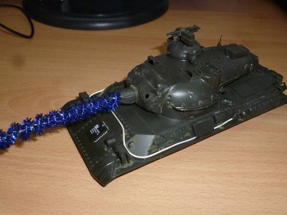
First of all, we need to glue our model Tamiya 35163. Open the box:

Start by extruding model details. The protruding parts or the remains of the frame should be cut with a knife or cleaned with sandpaper. We assemble the lower part of the body according to the instructions, you should not only glue the parts for installing the drive wheels. I just applied these details to take a photo:
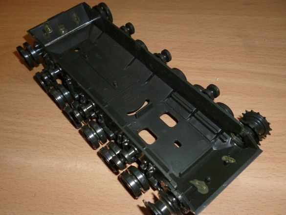
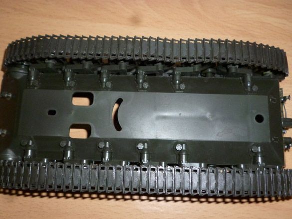
On the reverse side it looks like this:
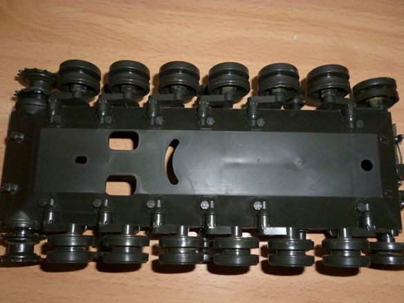
Be careful not to glue the wheel mounts with glue, all wheels should spin freely. Caterpillars at the junction should also be glued. After assembling the chassis, it is better to let it dry thoroughly before further actions:
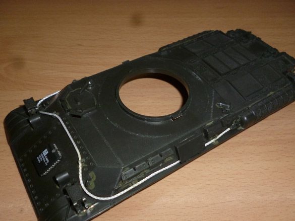
While the chassis dries, glue the top. First, the foundation. There are many small parts, it is better to use tweezers for gluing such parts. Glued base:
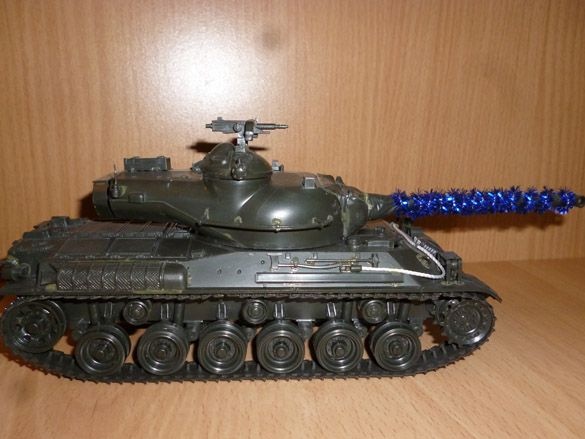
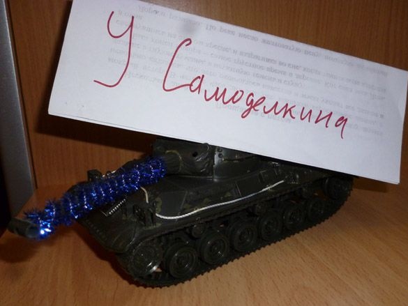
We collect the tower. Two options are available for the tower. The difference lies in the details of mounting the barrel to the tower. The first option is a standard mount, the second with dust protection. It’s worth choosing which one you like best. This difference is reflected only in appearance. He glued the model on New Year's holidays, so he dressed up the tank too:
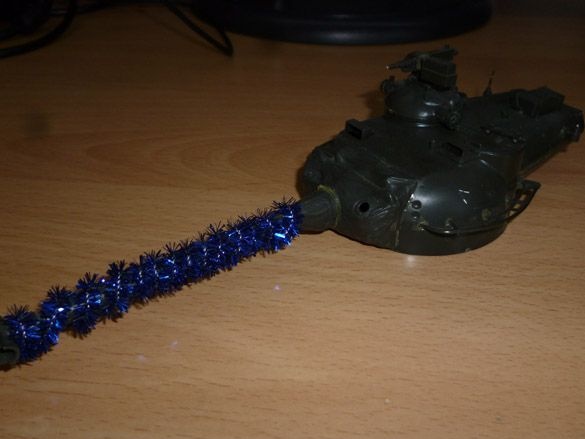
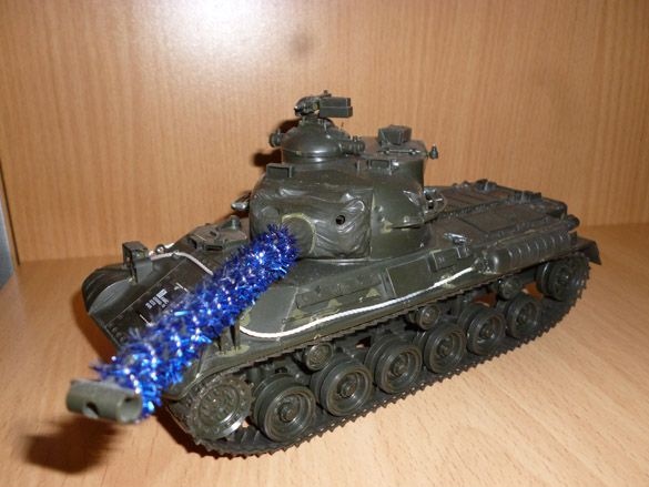
Put together and leave to dry:
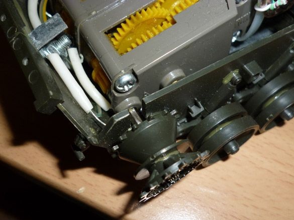
While the model is drying, let's move on to assembling the gear motor. We will use a gear motor and motors manufactured by the same company as the model, namely Tamiya 70097:
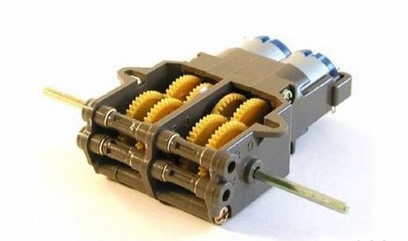
The instruction that comes with the kit does not have the Russian language, but it is already understandable.Two assembly options are described there in detail:
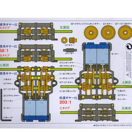
In the first case, the gear ratio is 58: 1, the second - 203: 1. We use the first option. The output shafts of the gearbox should be passed through the central holes. The side eyes of the gearbox should be cut, they will interfere with installation on the model. Otherwise, the gearbox is quite simple to put on the model. Then we put small gears on the motors and insert them into the gearbox. For each of the motors, a resistor of 2 ohms should be soldered to one of the contacts. We solder one wire to the resistor, and the second wire to the second contact of the motor. Having finished installing the motors, we put the assembled gear motor on the model. Fasten using glue.
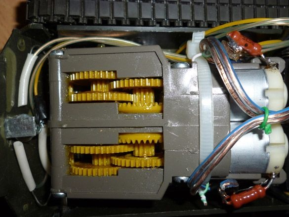
We also drive the driving wheels to the output shafts.
Future plans include adding the turret rotation function and, possibly, firing weapons. In the following instructions I will try to describe these modifications.
Step 2 Electrification.
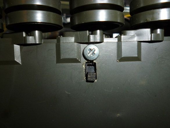
Having collected the model, and waiting for complete drying, go to e stuffing. In the lower part we cut in the switch:
Two battery compartments are soldered in series and glued together. We also output a convenient connector at the end of the wires.
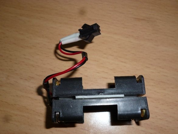
To power the model, you can use AAA batteries (“little ones”) or Ni-Mn 1.2 volt AAA batteries.
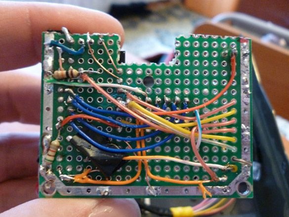
Take the ESP8266. This is a small but quite functional module, and the built-in Wi-Fi module provides connection to home Wi-fi network. I recommend choosing a module with 4 Mb of memory. To run and flash the ESP-8266 ESP, you must assemble a minimum binding. The module is powered by 3.3 volts. It cannot be connected directly to an unstabilized power source. Therefore, we include in the circuit a voltage stabilizer AMS 1117 3.3v. The VCC pin is connected directly to the positive power cable from the stabilizer, and the remaining pins: CH_PD, RESET, GPIO0, GPIO2, must be connected through a resistor, that is, pulled to the power supply (VCC). It is recommended to use 10kOm resistors, but they can be replaced with others from 4.7kOm to 50kOm. It is impossible to change only the GPIO15 resistor, its face value should be up to 10k. Directly, we connect only GND to the negative power wire (GND). To enter the module firmware mode, GPIO0 must be connected to GND. The button is needed to reboot the module when it is flashed. The conclusions of Tx, Rx, GND are made in the USB-TTL connector. The USB-TTL connection is as follows:
ESP 8266 - USB-TTL
Tx - Rx
Rx - Tx
GND - GND
The scheme is as follows:
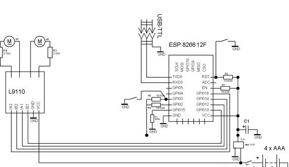
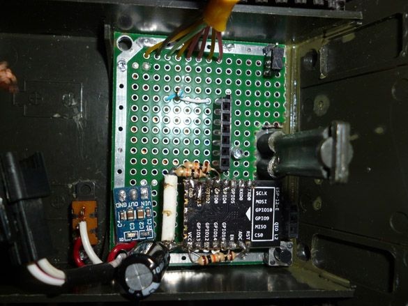
It’s most convenient to place it all on a small circuit board:
We fix the circuit board in the back of the tank:
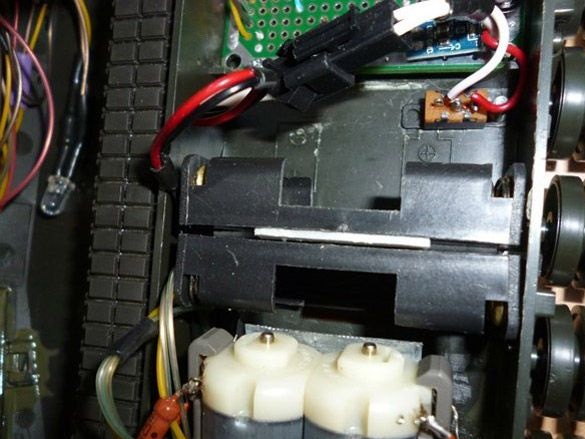
The battery compartment is placed between the gear motor and the circuit board:
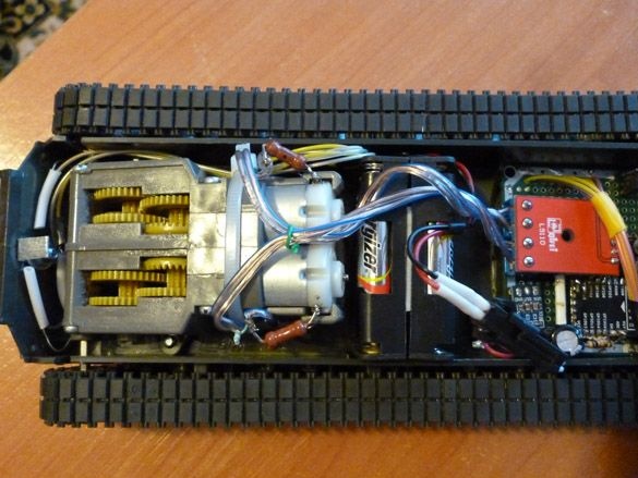
All assembled and installed electrics are located in the lower part of the tank:
Step 3 Software.
To edit and fill the sketch in ESP you need to download Arduino IDE from the official site
Arduino.cc.
Then install the Arduino IDE. After that, we proceed to install the add-on for ESP. We do this through the Boards Manager. First, start the Arduino IDE, then File - Settings - in the Additional Boards Manager URLs field, insert the link:
http://arduino.esp8266.com/package_esp8266com_index.jsonclick OK (you can enter several links separated by a comma in this field). Then go to Tools - Board - Boards Manager in the filter field, enter esp8266 and select ESP8266 by ESP8266 Community Forum. Click Install and wait for the download to finish. Now we select in the menu Tools - Board - Generic ESP8266 we set the frequency of your module 80 or 160Mhz, the size of flash memory. Then select the serial port to which the USB-TTL adapter is connected.
Now you need to install the tool to access the ESP file system. To do this, you need to move the files in the archive to the tools folder, which can be found in the root directory of the Arduino IDE.
Step 4 Sketch
Now that the programming environment is ready, let's move on to editing the sketch. Open the sketch:
At its beginning, we look for the field "String _ssid =" ";". Between the quotes, indicate which access point you want to connect to.
Field "String _password =" ";" - used to record the password for this network.
If the ESP cannot connect to the network indicated in the previous lines, the controller will create a network to which it can connect.
Field "String _ssidAP =" ";" - indicates the name of the network being created.
Field "String _passwordAP =" 12345678 ";" - sets the password of the created network.
Field "String SSDP_Name =" ESP_Wi-Fi ";" - sets the name of the SSDP.
Having edited all the lines above, you need to upload the web shell to the ESP 8266. We connect the ESP 8266 via USB-TTL to the computer according to the diagram above. In the Arduino IDE, select Tools - ESP8266 Sketch Data Upload. We are waiting for the end of the file upload process. Now you can record the sketch itself. First, put the ESP8266 into firmware mode. To do this, connect GPIO0 to GND. Press the sketch fill button, and then press the reset button on the EPS module. Waiting for the sketch to finish filling.
I’ll explain a little the algorithm of ESP 8266. When starting up, EPS tries to connect to the Wi-Fi network specified in the String _ssid field. If for some reason this failed, ESP raises its network with the name specified in the ssidAP field. In the first case, you can control the tank through any device connected to the same network. In the second case, you need to connect to the ESP through any device, tablet, phone or computer. Next, in the browser of the device through which we will control the tank, you need to enter the IP address of the tank. You can find out the IP address by connecting the ESP to the computer, then open the terminal window and restart the ESP. When launched, the IP address of the tank will be written in the terminal window. Or you can specify a fixed IP address assigned by ESP in the settings of the Wi-Fi router. Also, if you use a computer with Windows, you can go into the network infrastructure, find our tank there and double-click to connect to it. If the ESP itself raises the access point, the tank’s IP address will be 192.168.1.1.
The web interface is written in HTML and consists of two pages. The first contains control commands. On the second, you can change the settings of ESP 8266. On the settings page, the following parameters are available for change: the name of the access point to which you want to connect, the password of this access point, the name of the tank, the name of the network being created and the password for connecting to this network. All changes will take effect only after a reboot. The ESP reload feature is also available from the web interface.
After completing all the work, the tank can be painted using model paints. The painted tank looks prettier:
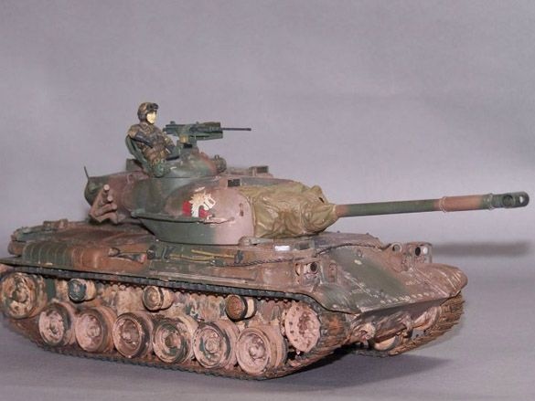
I do not have the patience for such a job. Therefore, my models are left without painting: