» Electronics »DIY microphone on 2 transistors

DIY microphone on 2 transistors


It was required to make a radio microphone for voice recording, for dubbing a video clip at a short distance.

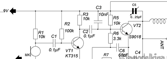
The choice fell on the standard "three-point capacitive" circuit.
Having spent some time searching for a circuit, a pretty good and stable option was found.
DIY microphone on 2 transistors

To translate the scheme into reality I needed:


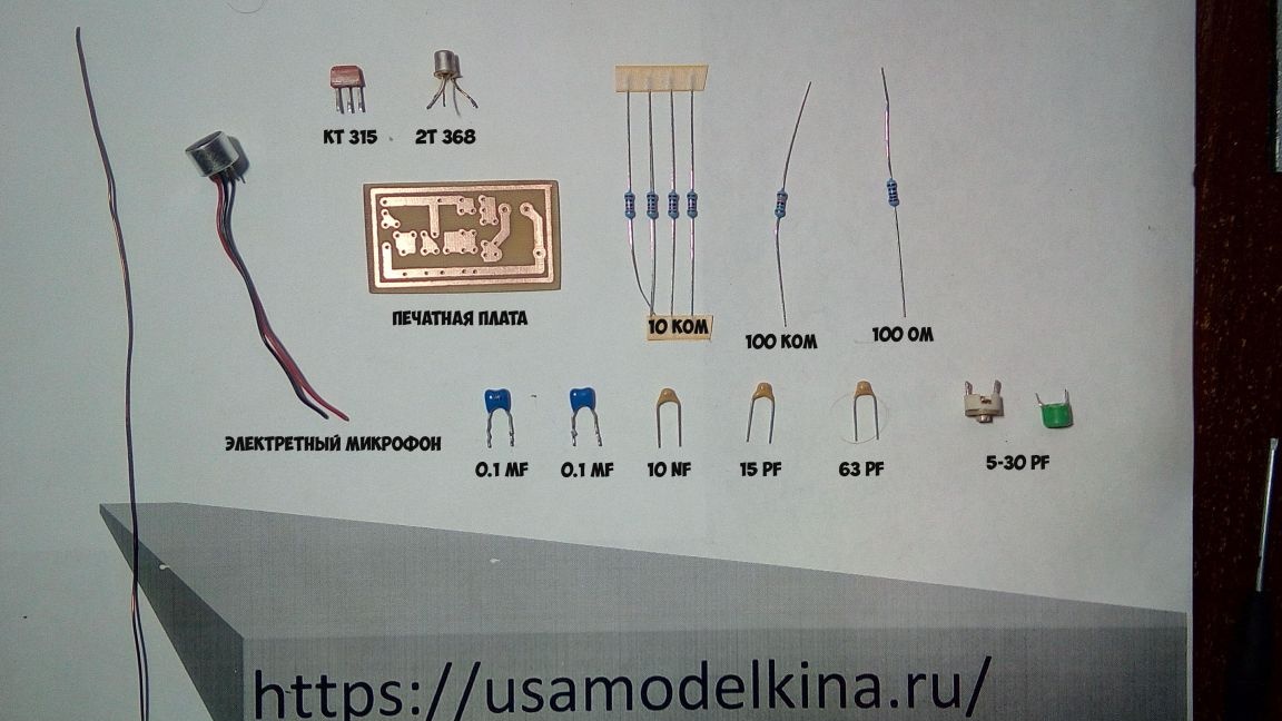
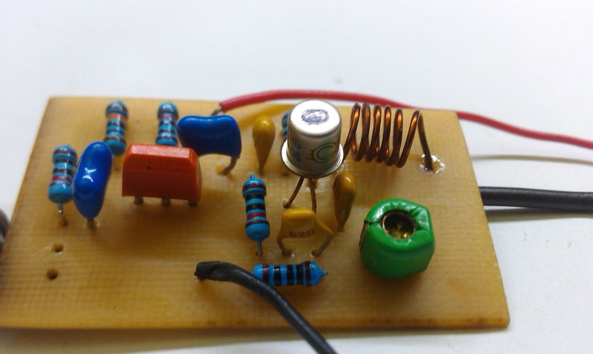
1) Transistors CT 315, CT 368
2) Resistors 100 kOhm, 10 kOhm (4 pcs), 100 ohm
3) Capacitors 0.1 mf (2 pcs), 10 nf, 15 pf, 63pf, 5-30 pf (Trimmer)
4) The coil contains 6 turns of wire 0.6-0.8 on the frame 4.5-5 mm
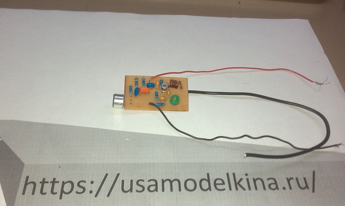
5) Electron microphone
6) Textolite, sandpaper, copper sulfate, salt.

with a printed circuit board, open in SprintLayout and print.

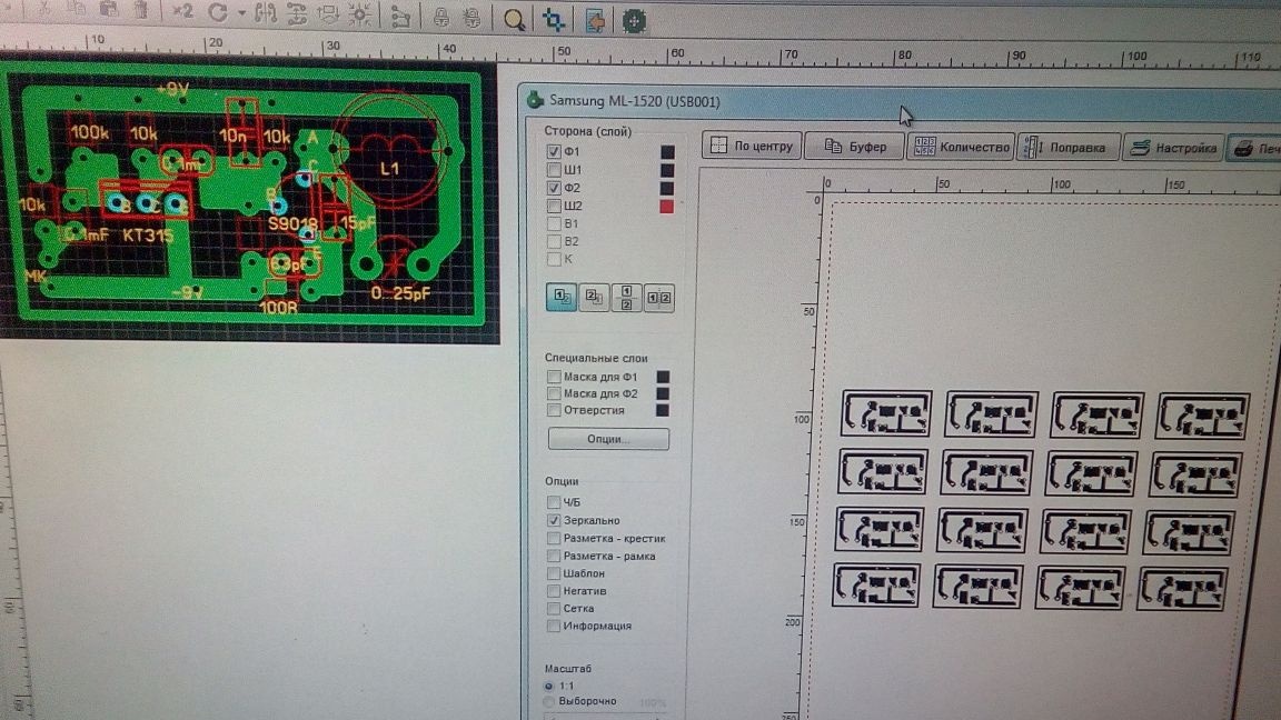
We prepare the template for further shamanism ...........

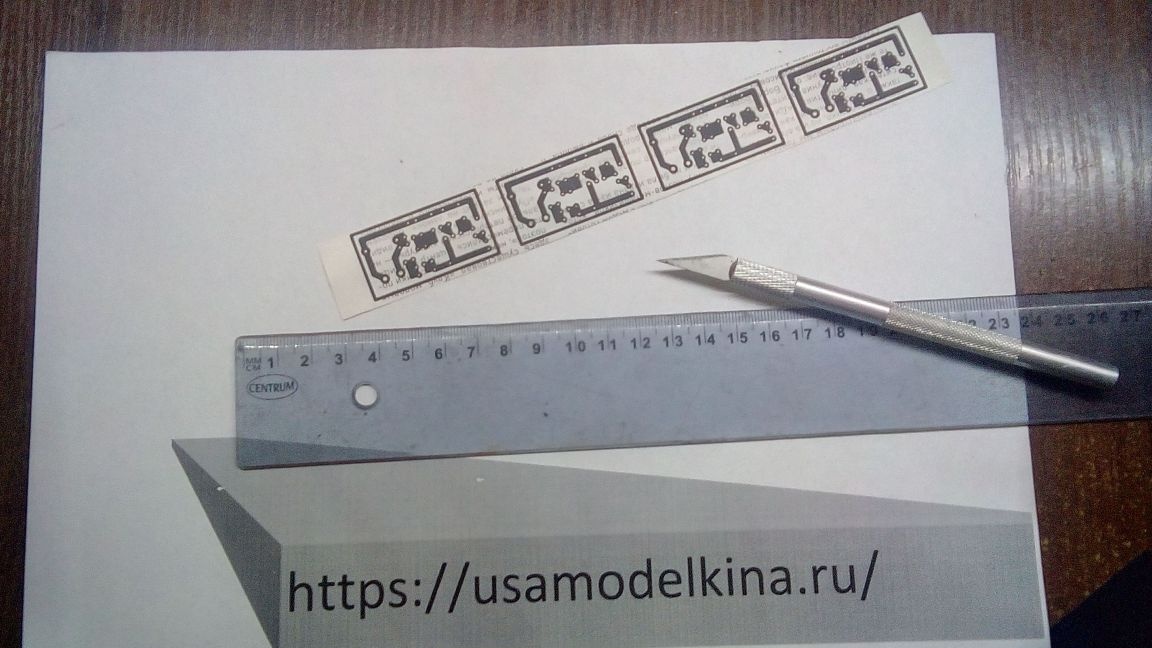
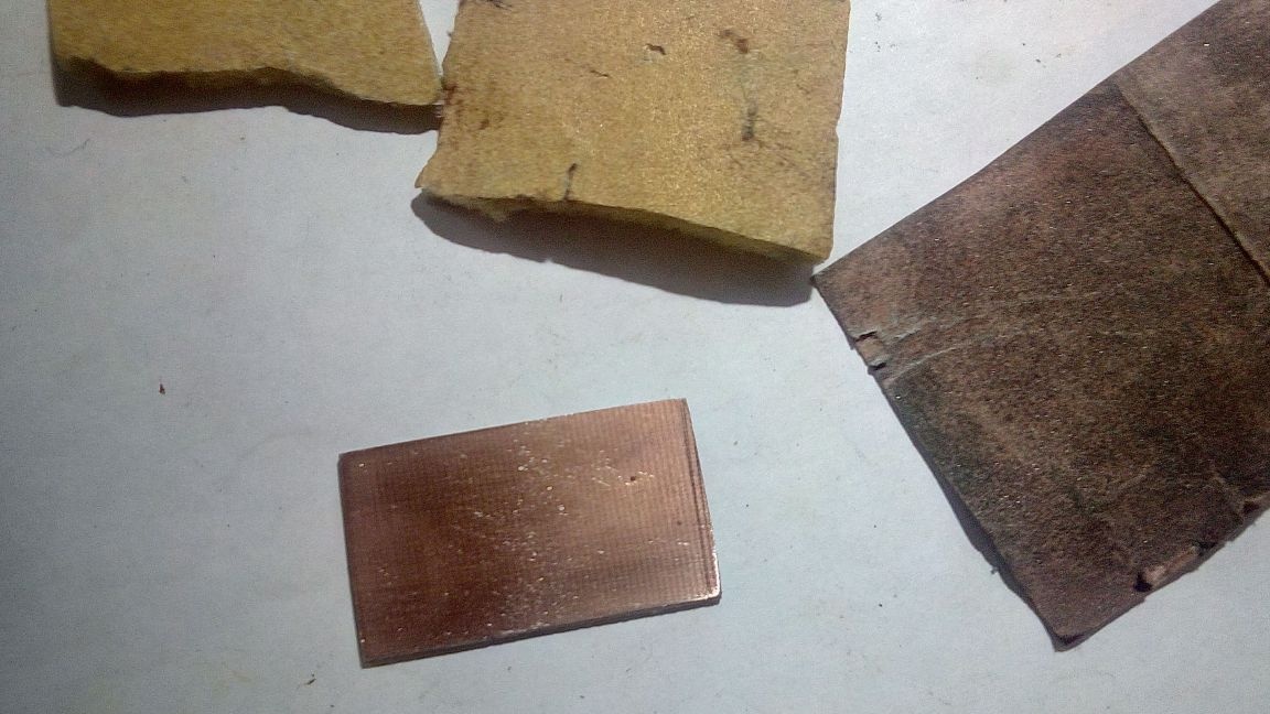
After you have prepared the template, we will take up the preparation of the PCB to obtain a high-quality printed circuit board
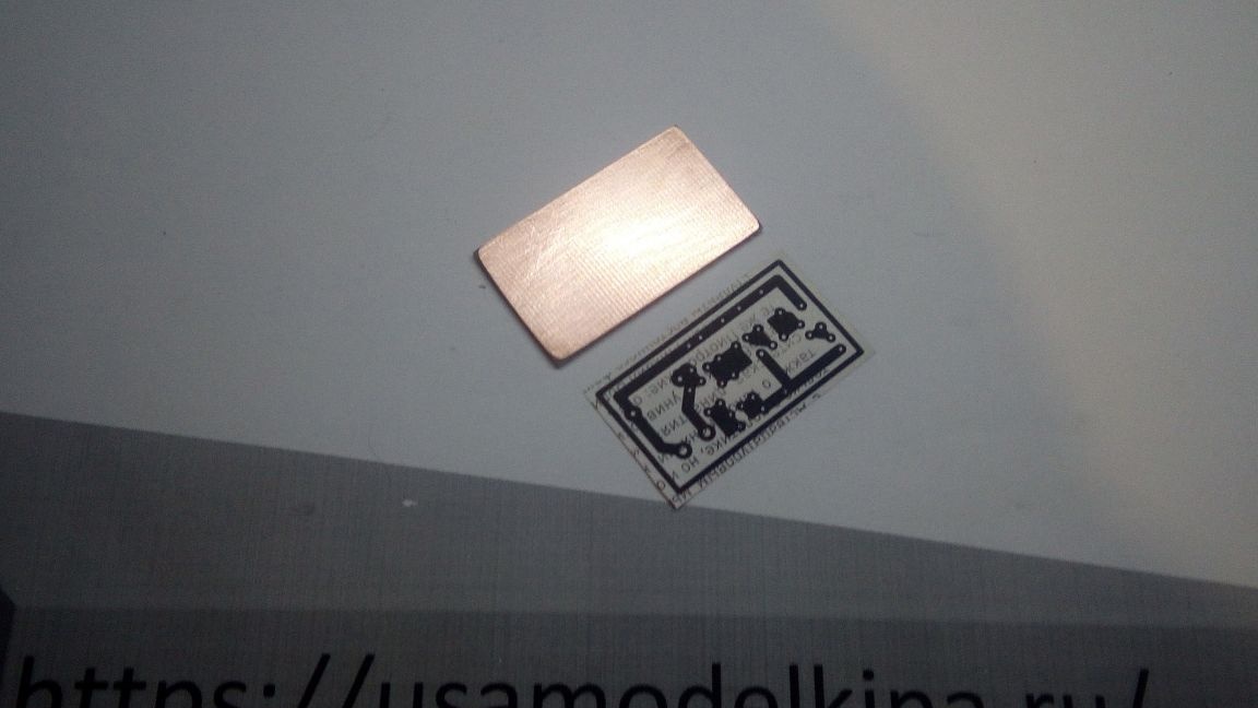
first wash, then skim, and wash again.


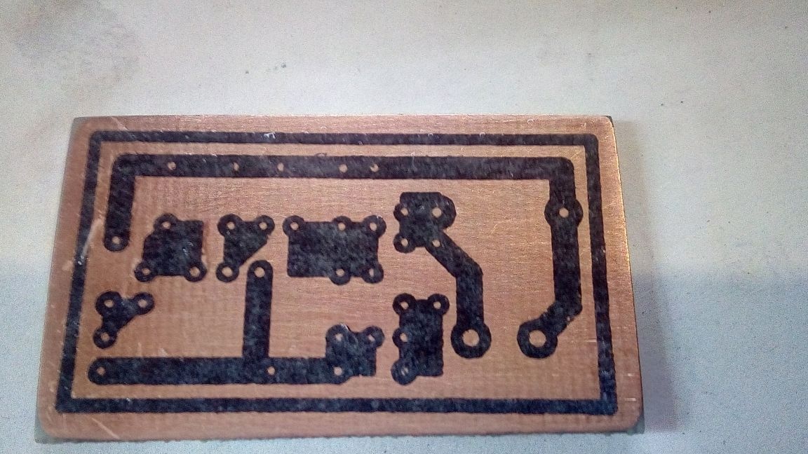
As a result, we get this result

Now it came to transferring the drawing to textolite, for which we need an iron and a flat one (preferably a wooden surface, I recommend ironing from 15 to 45 seconds. At the same time, pressing and warming the entire board well.

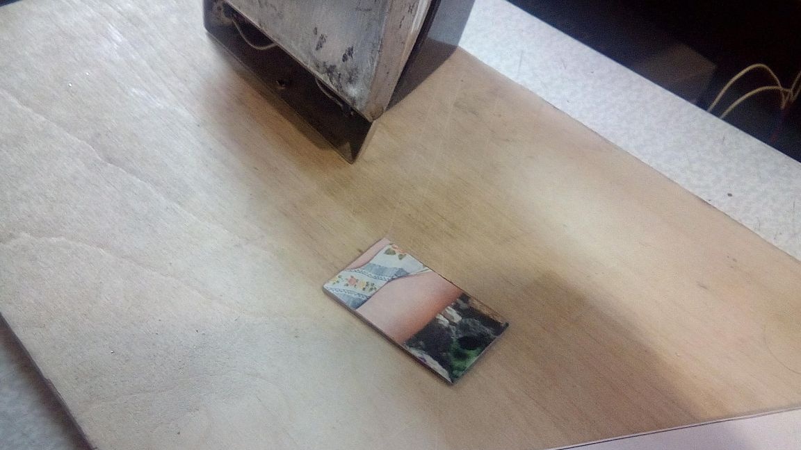
Next, let the board cool down and only after that dip it in a container of water for 2-5 minutes to soften the paper template.

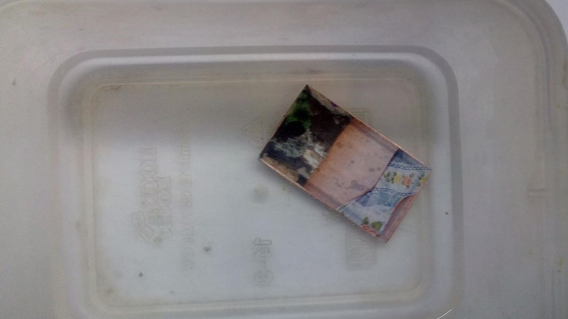
After removing the excess with a quality transfer of the picture, it should turn out like this

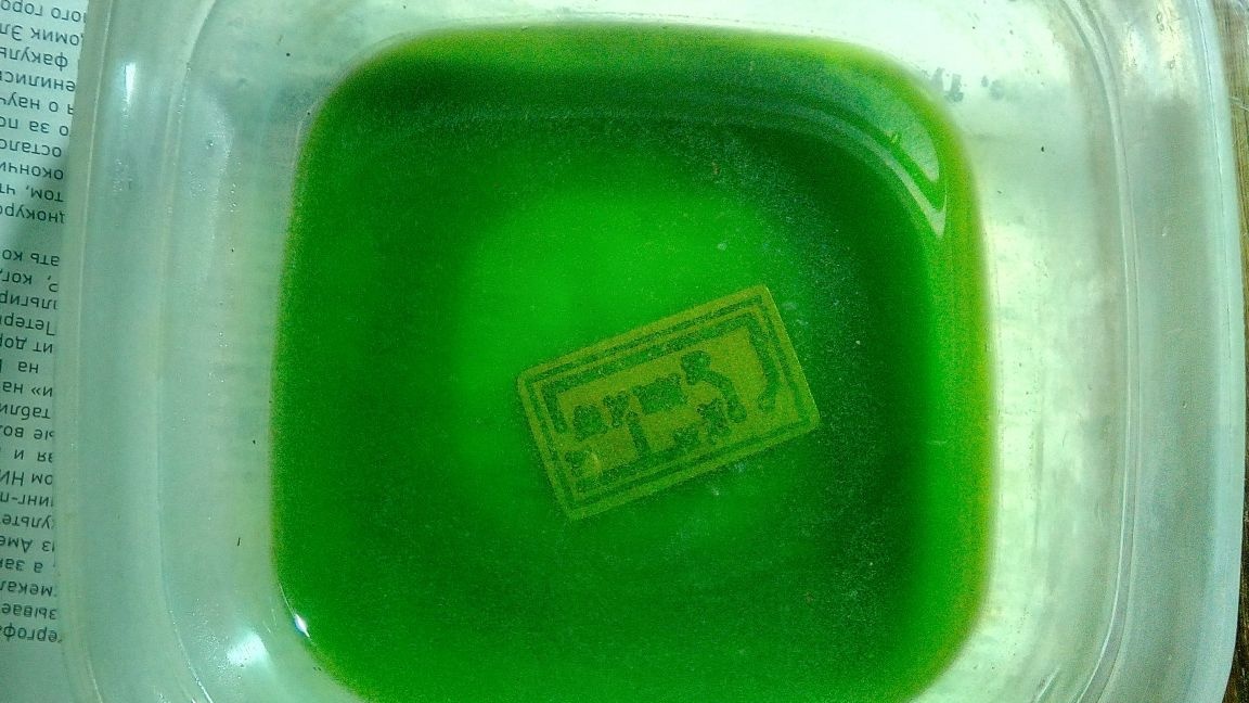
If all these operations are successful, we proceed to etching the board.
For etching, copper sulfate must be mixed with table salt, in a ratio of 1/3 of vitriol and 2/3 of salt.


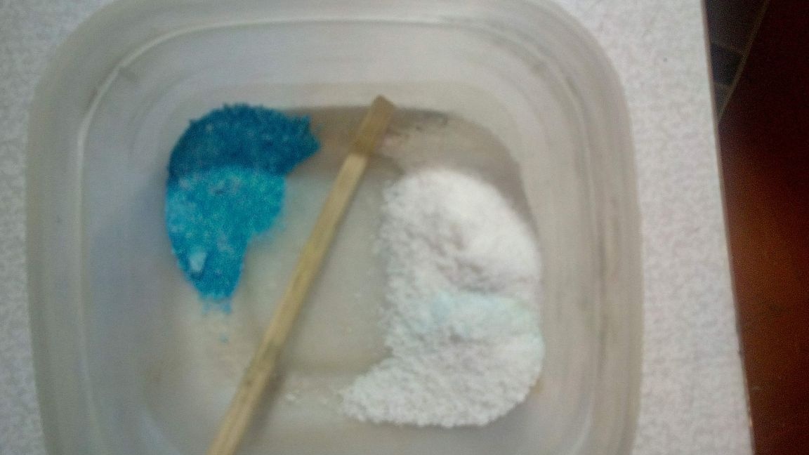
Pour boiling water, mix and lower our board

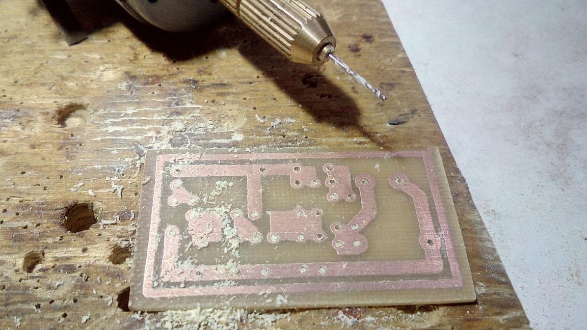
After etching, I wash the circuit board from the remaining toner and drill.

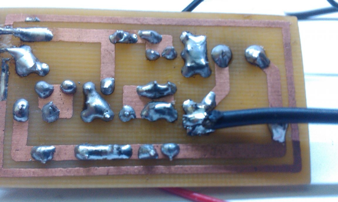
Next, we collect and get an almost finished product, it remains only to set up a little


To configure, we need a receiver and an RF field indicator that can be assembled according to the scheme below

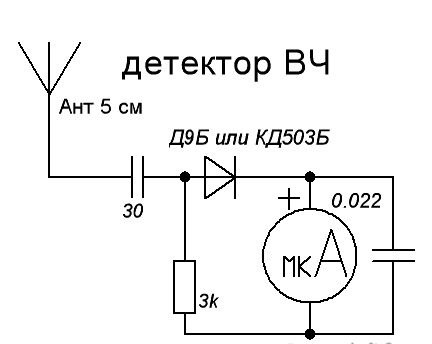
I used an SDR receiver and a homemade RF / microwave field indicator for tuning.
Work video
6.5
7.5
8

Add a comment

    • smilesmilesxaxaokdontknowyahoonea
      bossscratchfoolyesyes-yesaggressivesecret
      sorrydancedance2dance3pardonhelpdrinks
      stopfriendsgoodgoodgoodwhistleswoontongue
      smokeclappingcraydeclarederisivedon-t_mentiondownload
      heatirefullaugh1mdameetingmoskingnegative
      not_ipopcornpunishreadscarescaressearch
      tauntthank_youthisto_clueumnikacuteagree
      badbeeeblack_eyeblum3blushboastboredom
      censoredpleasantrysecret2threatenvictoryyusun_bespectacled
      shokrespektlolprevedwelcomekrutoyya_za
      ya_dobryihelperne_huliganne_othodifludbanclose
13 comments
Having spent some time searching for a circuit, a pretty good and stable option was found.
For some reason, of all the schemes on the Internet, they will often choose the most lame.What stability can we talk about when the generator is directly connected to the antenna? With any change in the position of the antenna in space (or even just bring a hand to it), the transmission frequency will change (and within a fairly wide range, so that no AFC can handle it). There is only one way out - add another high-frequency amplification cascade after three points to decouple the generator from the antenna, coordinate this cascade with the antenna itself and carefully shield everything. Then it will be possible to achieve more or less stable operation and "range" of the device. But even with a stabilized power supply voltage, which is impossible from the batteries, in principle. When the battery is depleted, the frequency will still walk, just like when the ambient temperature changes.
Quote: Korolev
probably the maximum output signal.

Not. This is just an indicator of the RF field. It will easily detect any RF fields of sufficient power. Its use in this homemade product is completely unnecessary.
The three-point will generate oscillations with the frequency of the contour setting. And the maximum and minimum of the signal depends on the ratio of C4 and C6.
That is exactly what I wanted to say.
Once, setting up an industrial set of radio microphones before the conference, I caught someone else’s conversation, I realized by the content of the conversation “bug”, invited the head of the Security Council, did not become interested in the results of his work ...)))
Not sure, but likely maximum output.
This indicator can only check the very fact of the presence of generation, but it is easiest to adjust the circuit using a receiver tuned to the desired frequency.
The output circuit of the transmitter is adjusted according to the maximum deviation of the arrow, more precisely, it agrees with the "three-point".
Not even megaamperes: the letter "a" is lowercase, that is, in fact, it is generally unknown what.
To configure them, of course, is in principle impossible. If its antenna is located next to the transmitter antenna, then if there is a certain frequency in the last generation, the arrow will deviate.
And what, in fact, is to configure with this “receiver and RF field indicator”?
My friend was almost swept over for a similar thing.
The indicator diagram is probably downloaded from tyrnet, and if you really find fault, then the designation on the device is Megaamps!
The coil contains 6 turns of wire 0.6-0.8 on the rim 0.4-0.5 mm
Yes, you are a jeweler, my friend! )))
And the indicator of the RF field, probably, should not be used as a milliammeter, but as a microammeter?

We advise you to read:

Hand it for the smartphone ...