

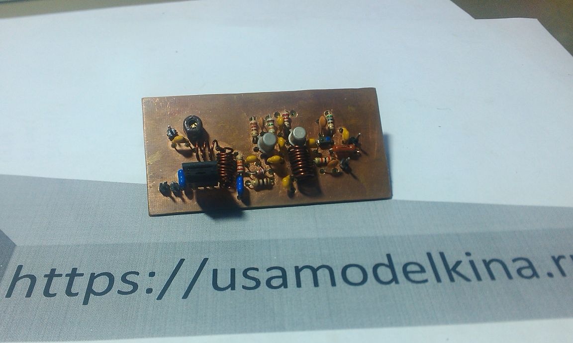
It is assembled according to the scheme below
For manufacturing, we need:
Soldering Iron, Rosin, Tin
Condensers:
1500 pf 4pcs
100 nf 3pcs
15 pf 2 pcs
3.3 pF 2 pcs
5-25 pF (tuning)
Resistors:
470 ohm 2 pcs
100 ohm
56 ohm
35 ohm
15 kOhm
22 kOhm
2.2 kOhm
1 kOhm
Transistors:
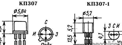
KP 307 2pcs
Bfg 135
Varicap KV 109
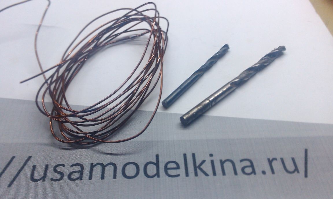
Wire in varnish insulation 50 cm
Drill 3 mm, 5mm
Stabilizer L7809
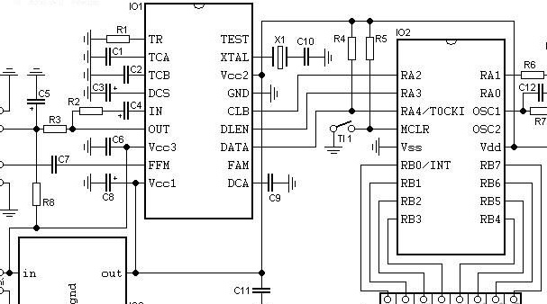
For frequency stability, I used the easiest frequency synthesizer to build.
And so that he is:
Power supply: 8-15 V stable, current - 40 mA
Frequency Range: 82.5-108 MHz
step frequency: 100 kHz
RF input, voltage range: 10-500 mV
RF Input Input Resistance: 135 Ohm
We will need:
Capacitors:
C1, C12 - 2.2 nF (ceramic)
C2, C9 - 10 nF (ceramic)
C3 - 47 uF (Electrolyte)
C4 - 10 uF (tantalum)
C5 - 0.47 uF (Electrolyte)
C6, C11 - 100 nF (ceramic)
C7 - 1 nF (ceramic)
C8 - 220 uF (Electrolyte)
C10 - 22 pF (ceramic)
Resistors:
R1 - 1k
R2 - 4k7
R3, R4, R5, R7 - 10k
R6 - 1k (not on the board)
R8 - 47k (not on the board)
Chips and more:
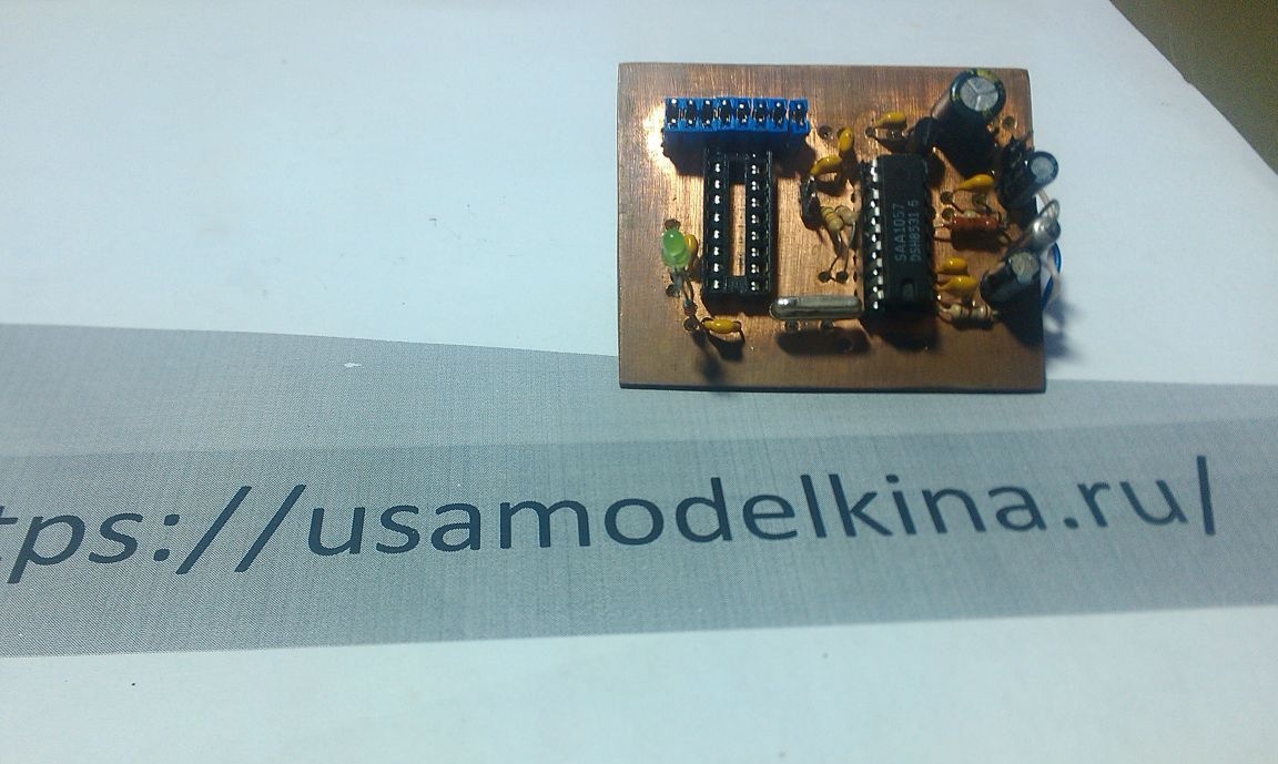
IC1 - SAA1057
IC2 - PIC16F84 (programmed) + socket
IC3 - 78L05 (KREN5A)
X1 - 4 MHz quartz crystal
D1 - LED
TL1 - Button
DIP switches
Instructions:
The Tl1 button resets the microcontroller. Press it after setting a new frequency. The controller resets after turning on the power, so you can not press this button.
LED D1 initiates frequency capture and synchronous operation (One second after a reset). You can not use it, and R6 is not needed.
Resistor R8 determines the minimum voltage (about 2 V) at the PLL output. Use this resistor if the transmitter does not work well when approaching this voltage (usually immediately after turning it on). Install it near R3.
The PLL pin should not be loaded directly with large capacitances (Approximately 0.3 μF). The synchronization cycle may be intermittent (Usually used in some unknown transmitters.
On the schematic diagram, in the initial version, the resistor value is R1 180 Ohm, this results in narrow-band frequency modulation, and we need broadband, so the value of this resistor should be 1k.
The synthesizer will connect to the transmitter with the same currents on its board. Terminals 1–1 and 2–2 can be connected using conventional mounting wires, and terminals 3–3 and 4–4 are best connected with a piece of thin coaxial cable.
A 0.47μF C5 electrolytic capacitor can be found on the boards of Chinese receivers, but I replaced it with a 1μF electrolyte.
Tantalum capacitors are found in large quantities on the boards of old Soviet TVs and tape recorders, but you can also put a regular electrolyte.
The synthesizer LED does NOT initiate frequency capture, but simply lights up. So when setting up, you need to use the control receiver.
And so, after everything is set up, you need to make sure that the harmonics of the transmitter do not go beyond the 108 MHz band.
To do this, we assemble an easy-to-assemble filter according to the scheme below.
Coils:
50 ohms ....
Single Layer Spool
Coil Inductance: 0.090 μH
Frame diameter: 8 mm.
Wire diameter: 1 mm.
Pitch between turns: 1 mm.
Number of turns: 3
Capacitors:
54 pf 2 pcs
27 pf 2 pcs
75 ohm .....
Single Layer Spool
Coil Inductance: 0.135 μH
Frame diameter: 8 mm.
Wire diameter: 1 mm.
Pitch between turns: 1 mm.
Number of turns: 4
Capacitors:
18 pf 2 pcs
33 pf 2 pcs
As a result, we get
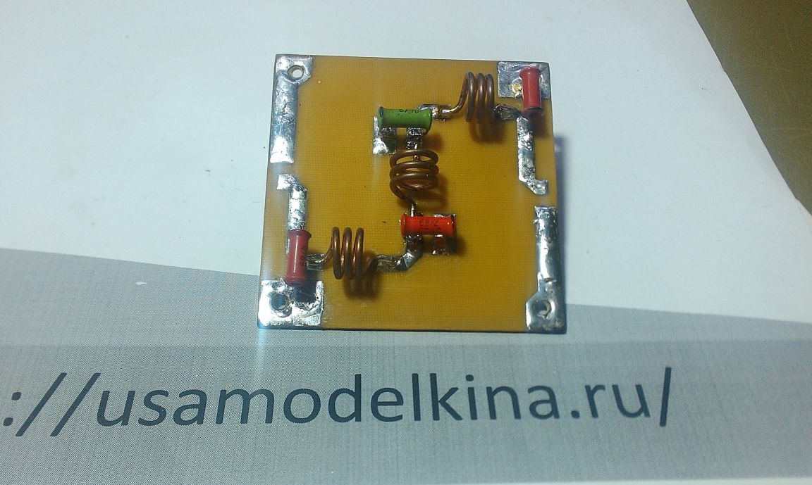
The entire assembly process can be seen in the video