
Greetings the inhabitants of our site!
The topic of soldering equipment is an important part on the YouTube channel Open frime tv and continuing its author, the channel will collect here such a rechargeable soldering iron on non-burnable tips.
The author has already collected several rechargeable soldering irons, but they were on copper tips, and constantly grind and clean the tip is still a problem, especially if you have to solder a lot, for example, for work. But, as they say, evolution does not stand still, and now the master presents all lovers of homemade products an improved version of the battery soldering iron with the so-called "eternal" sting. Such a sting does not need grinding and stripping. Unlike the sting made of copper, the “eternal” sting is cleaned of soot very simply - with a damp cloth or sponge dipped in glycerin. No more files. I think this homemade product will come in handy to many. The resource on a single charge is 30-40 minutes, this is enough to solder most circuits, I think this time on a single charge is quite imaginable. The soldering iron is equipped with an indicator LED that shows whether the soldering iron is on or not. There is also a built-in socket for recharging a lithium-ion battery, in this case, standard 18650, and of course this design is equipped with a switch. The dimensions were minimalistic, it is very convenient, put in a backpack and calmly moved where necessary.
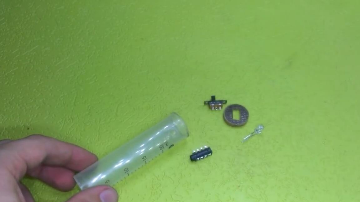
Warm-up time is approximately 40-50 seconds. Let's see for a start what we need to build.
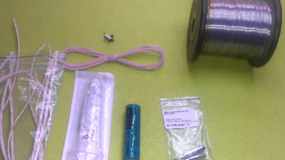
1) First of all, for the independent manufacture of such a soldering iron, we need a lithium-ion battery, and the larger the capacity, the better.
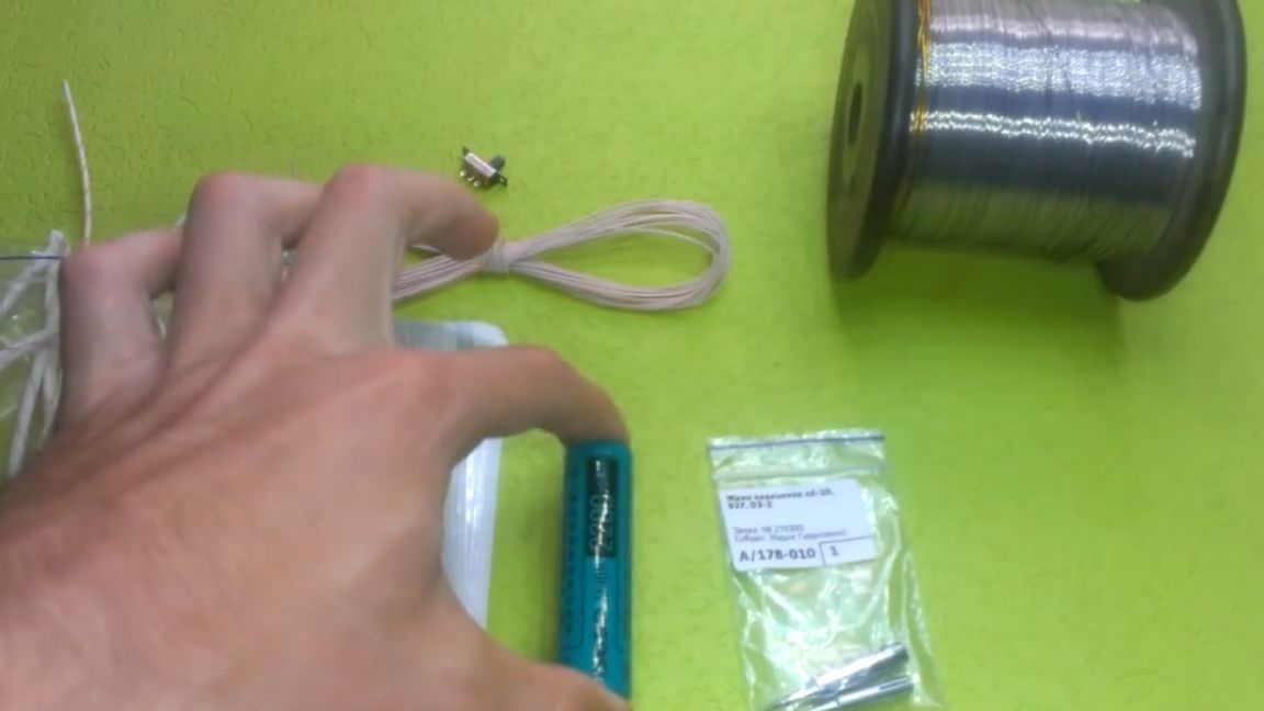
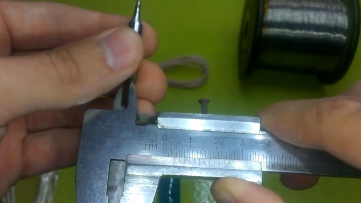
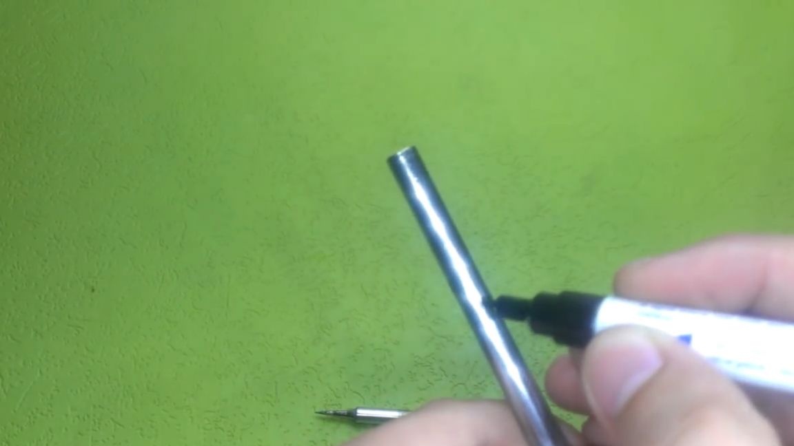
2) Next, we also need a sting. It can be taken from any soldering station, only you need to look so that the hole has a diameter of not less than 4 mm.
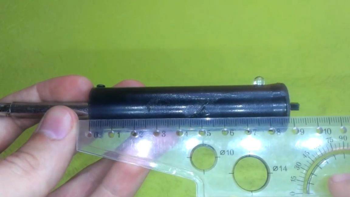
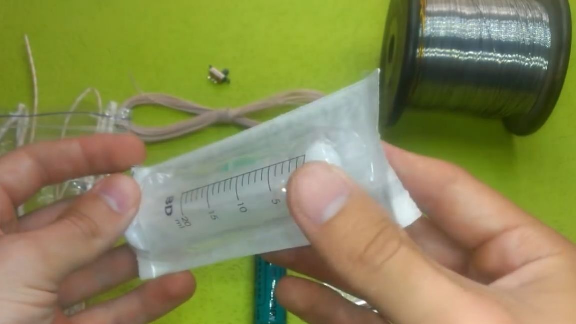
3) We will also need a case. A 20 cc medical syringe does an excellent job of this task.
4) Well, then on the little things: nichrome, fiberglass and connecting wires. You will already see all this directly during assembly.
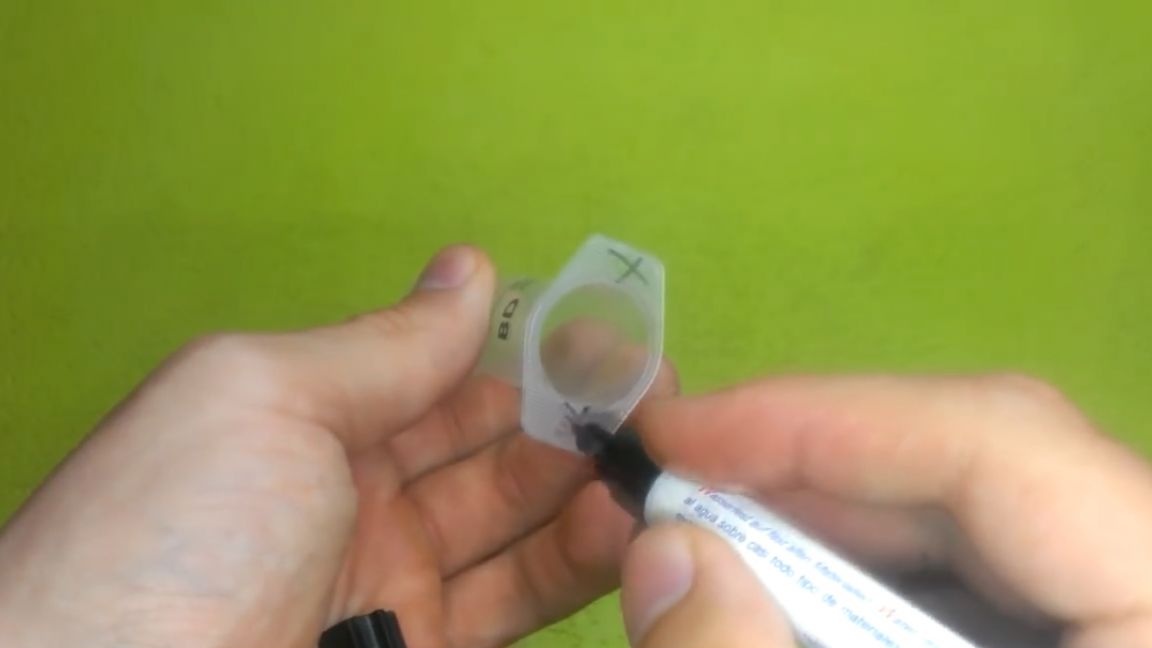
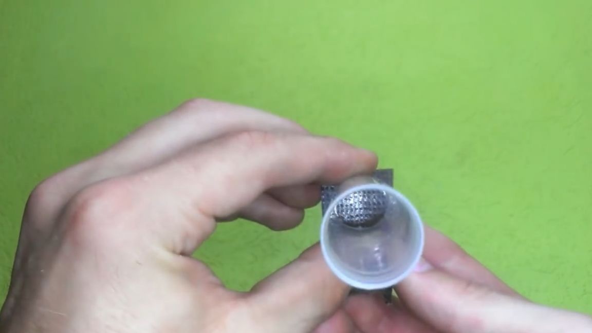
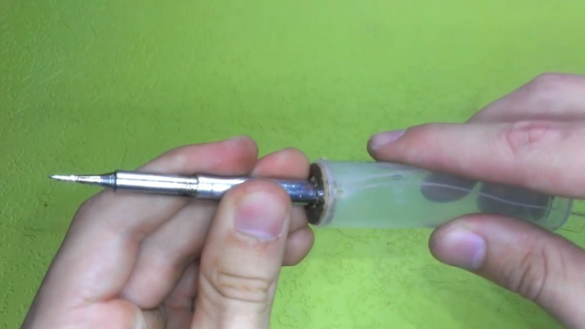
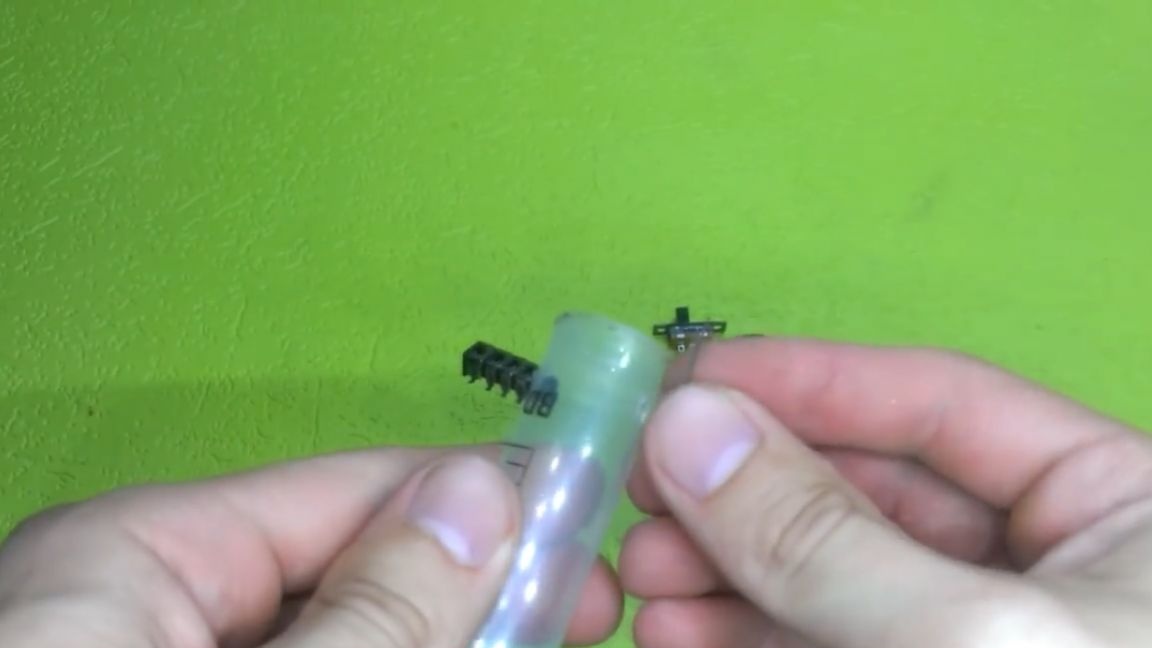
So, let's get down to manufacturing. Let's start preparing the case. We remove excess elements from the syringe: the lower part and side ears.
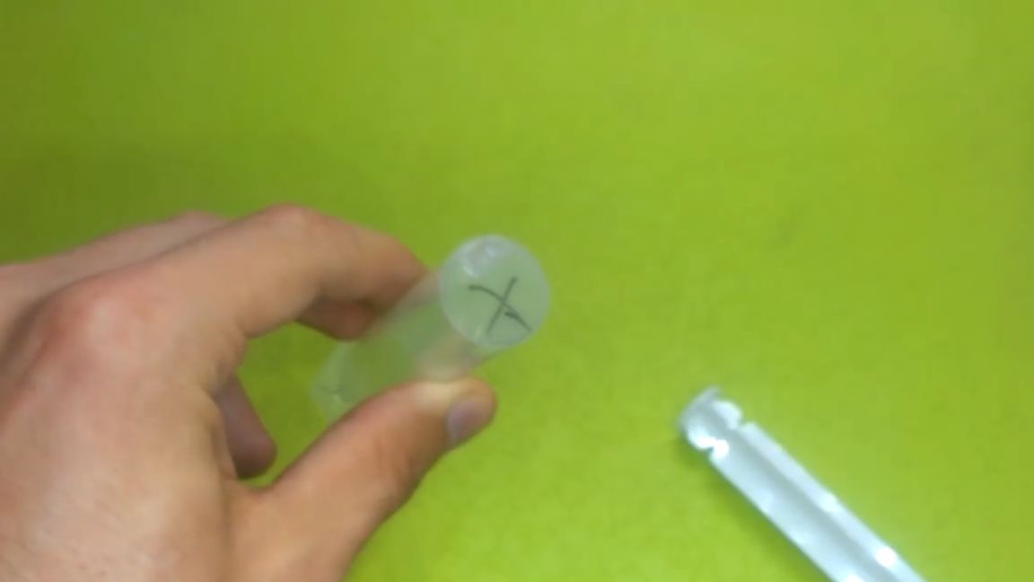
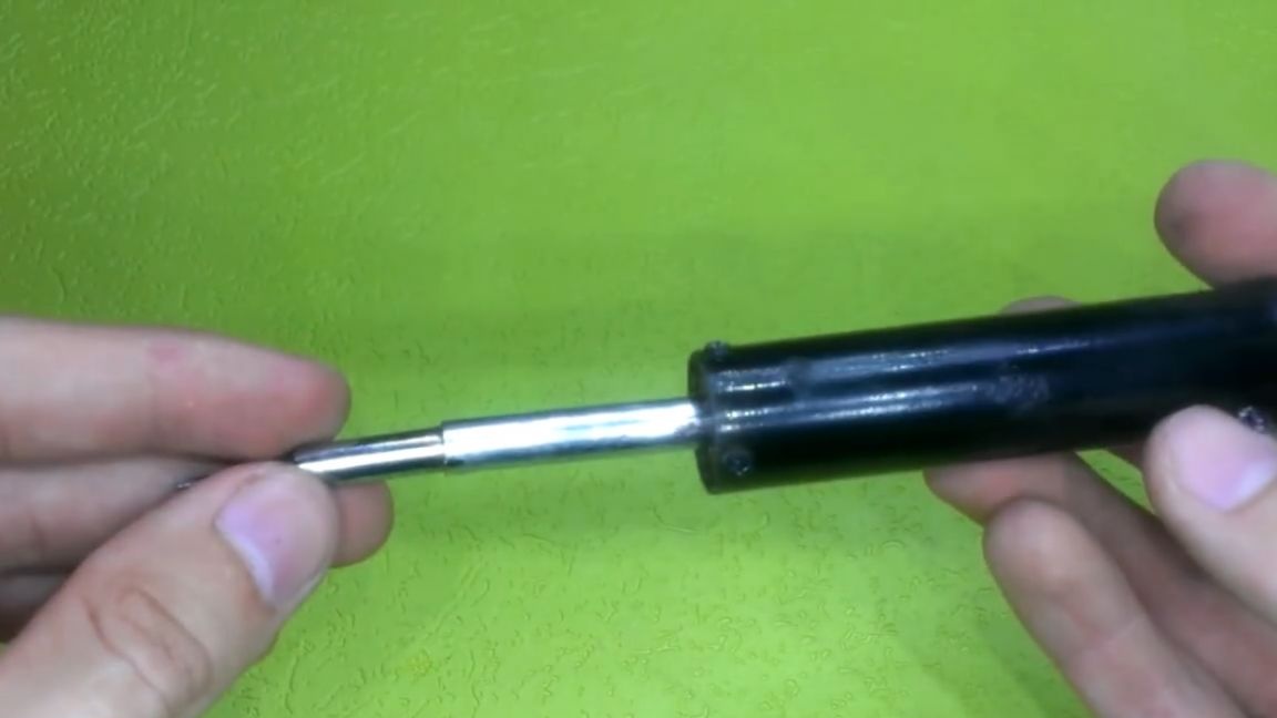
We figured out the syringe, now we will make a holder for the sting. For this purpose, we will use just such an extension tube.
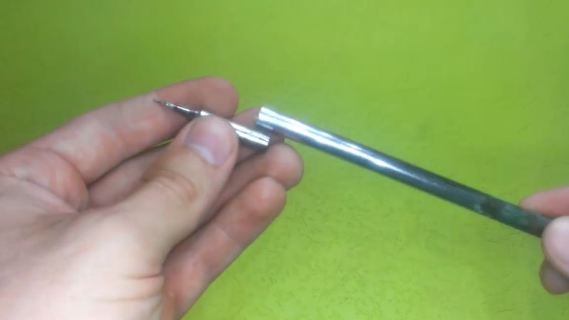
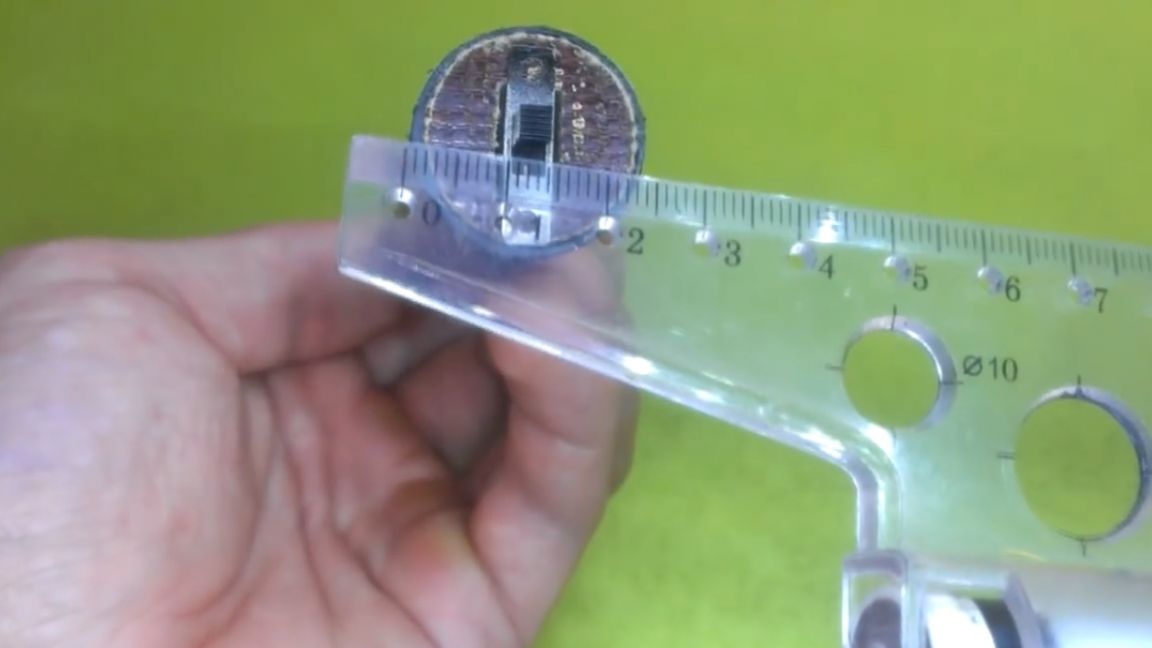
It is impossible to install directly near the case, it can melt.Therefore, for fastening to a syringe, we will use a 4 mm textolite.
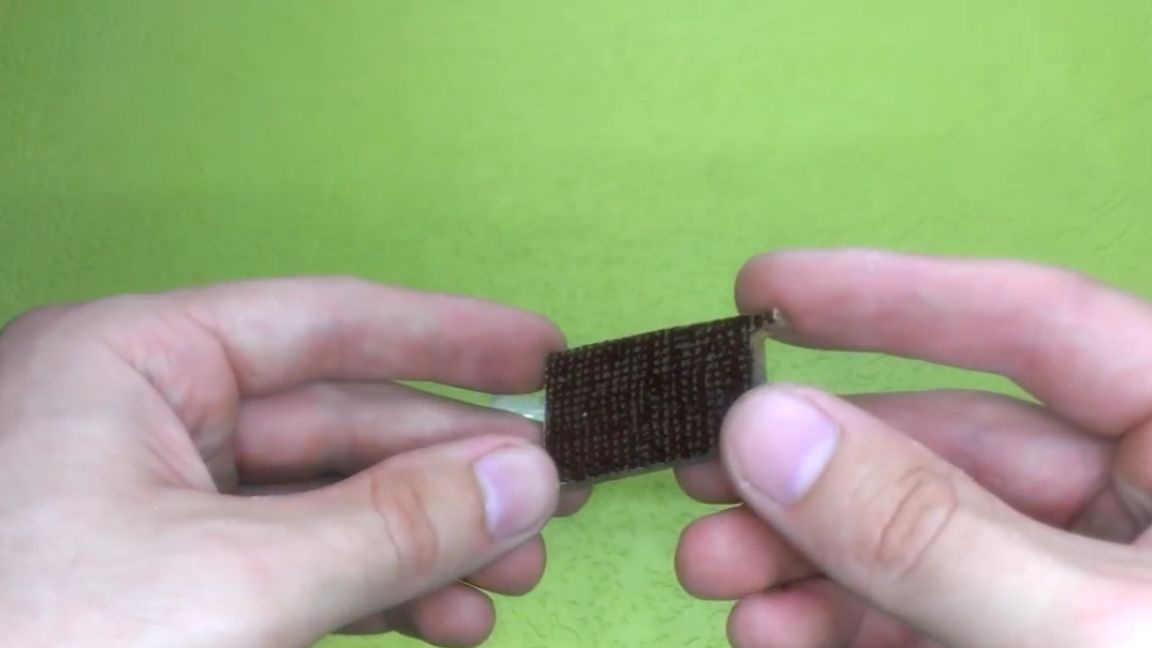
We will cut a “round” from it according to the diameter of the syringe, and an extension tube will be attached directly to this round.
It is also necessary to make holes for small screws for reliable fastening, if there is play, the soldering process will begin to annoy.
When we figured out the mount, we begin to make a heater. To make a heater, take a nichrome wire. Unwind by eye and connect to the laboratory unit.
We set the voltage at 3.7 V. On it, changing the length of the nichrome, we achieve a weak heating of the spiral, approximately as in this picture:
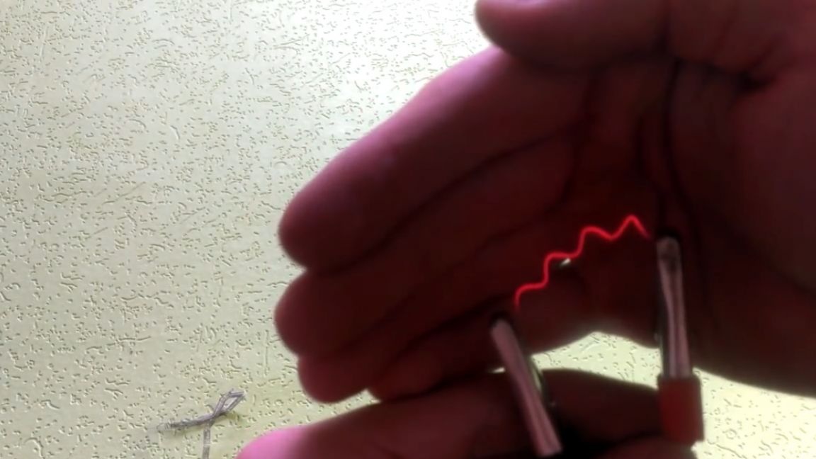
Not much to red, but the heat should be visible. Immediately answers to questions - where to get nichrome? There are many such devices: these are old hair dryers, curling irons, kettles, in general, everything that once warmed up.
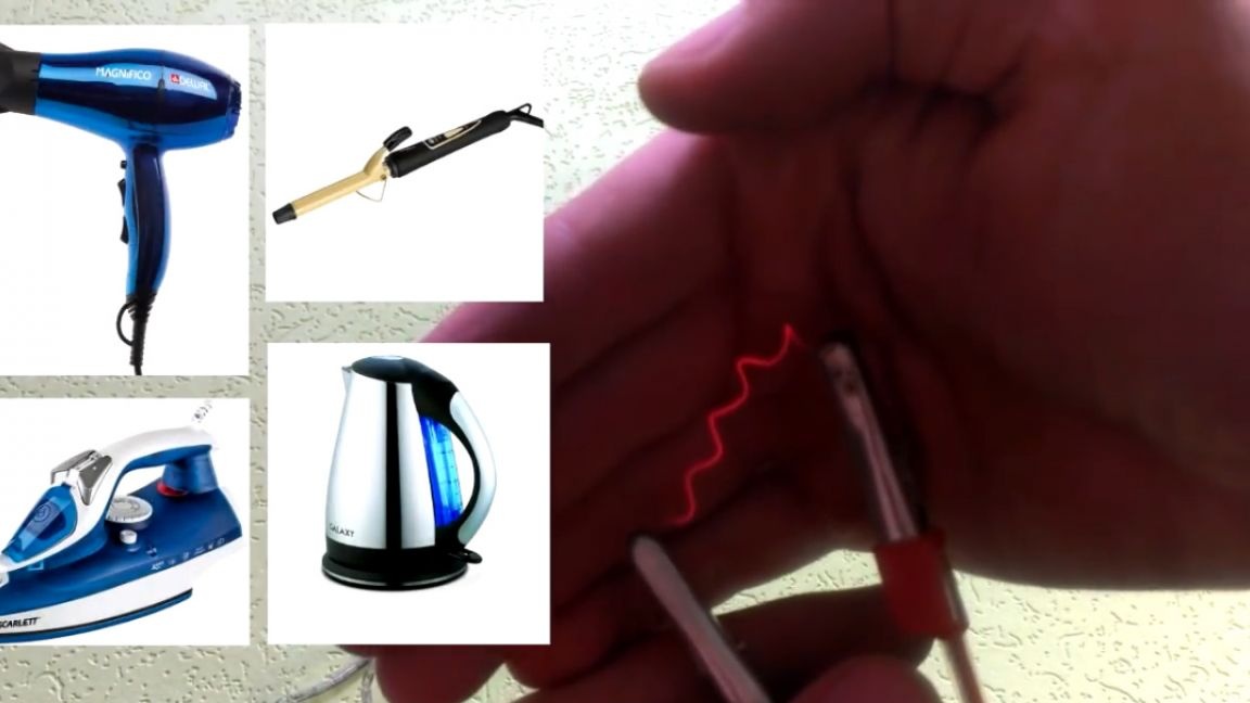
As you can see, at first the author wanted to use nichrome from a reel, but then decided to take it from an old hairdryer to demonstrate his words.
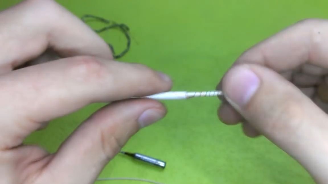
The heater needs to be wound on some frame. The author decided to use copper wire. We put a glass tube on it a little more than the length of the sting itself, fasten the mounting wire to nichrome and wind it evenly across the entire surface without a short circuit. When wound, we put on another glass tube of a larger diameter to protect against short circuit from above and fasten the second terminal.
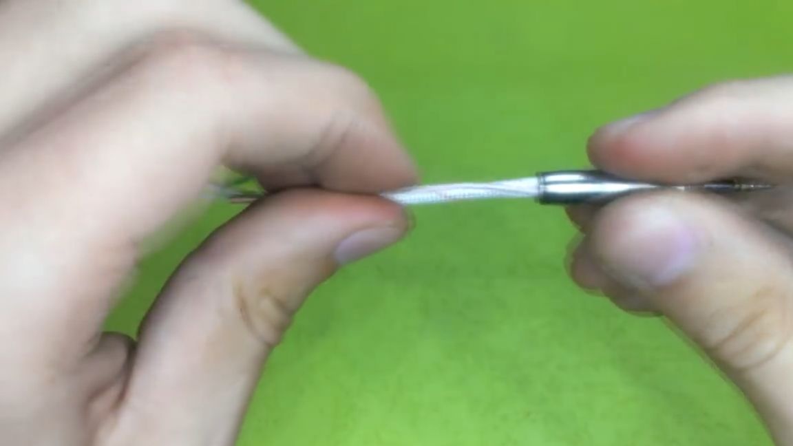
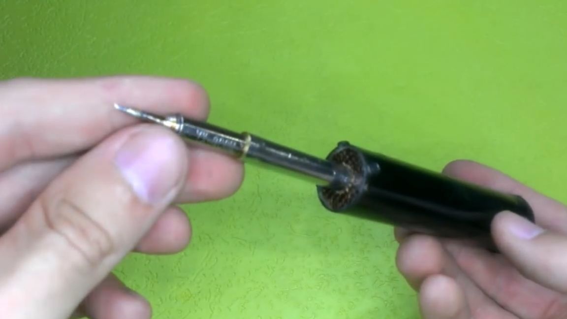
Next, put the heating element in the sting. As you can see, he hardly goes inside. Great, no extra gasket needed. After this, it is necessary to make a control inclusion, whether there is bad contact or something else.
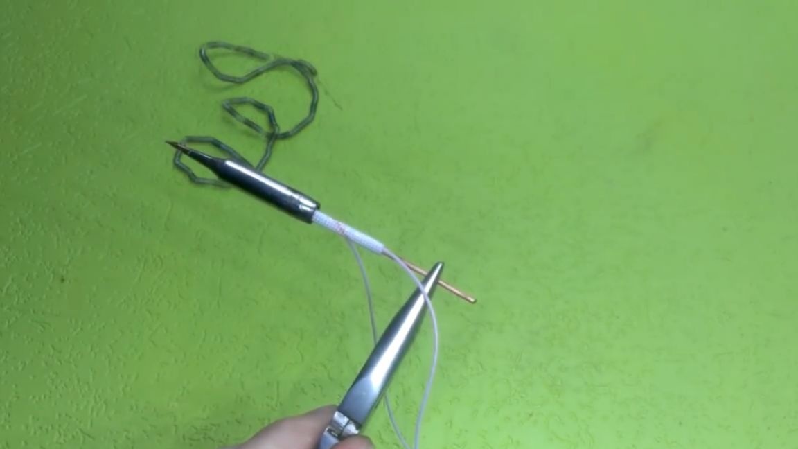
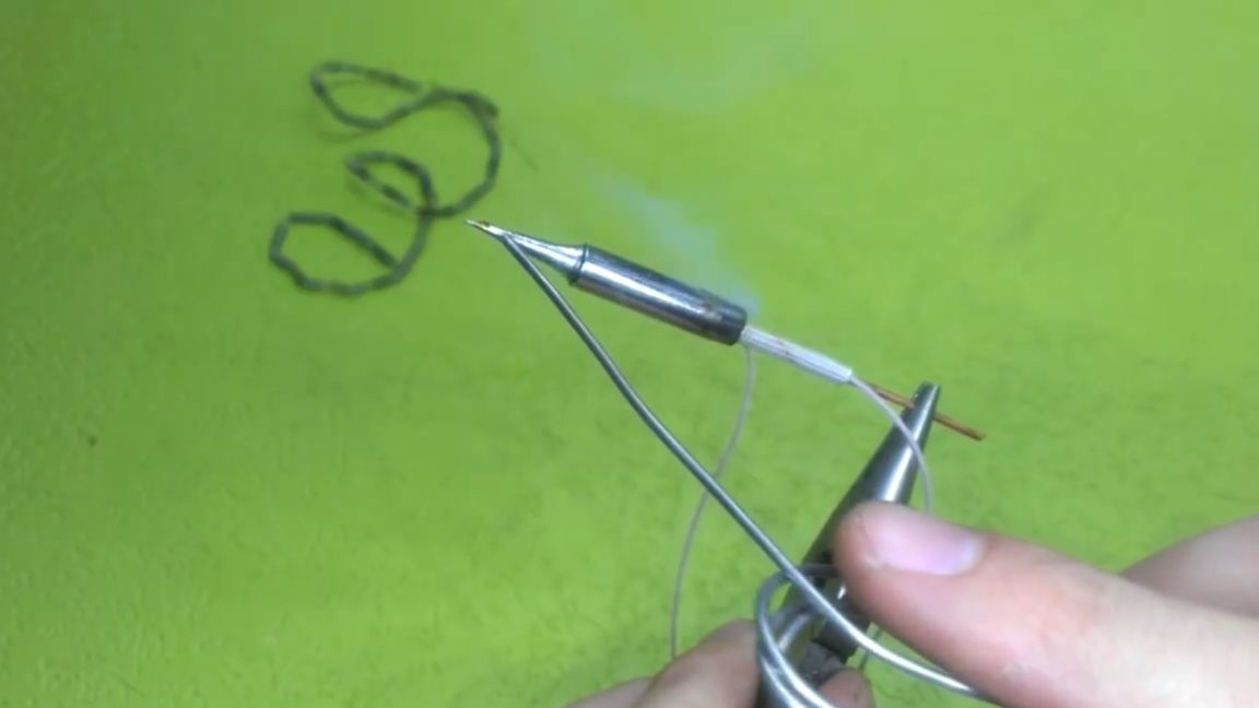
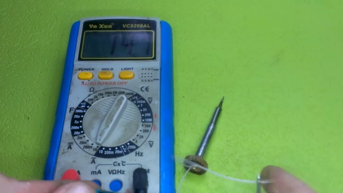
It should be noted that the first inclusion must be carried out in a well-ventilated room, since a lot of smoke is released when the glass tube is heated. The test was successful. You can also measure the current consumption, it should be in the region of one and a half amperes.
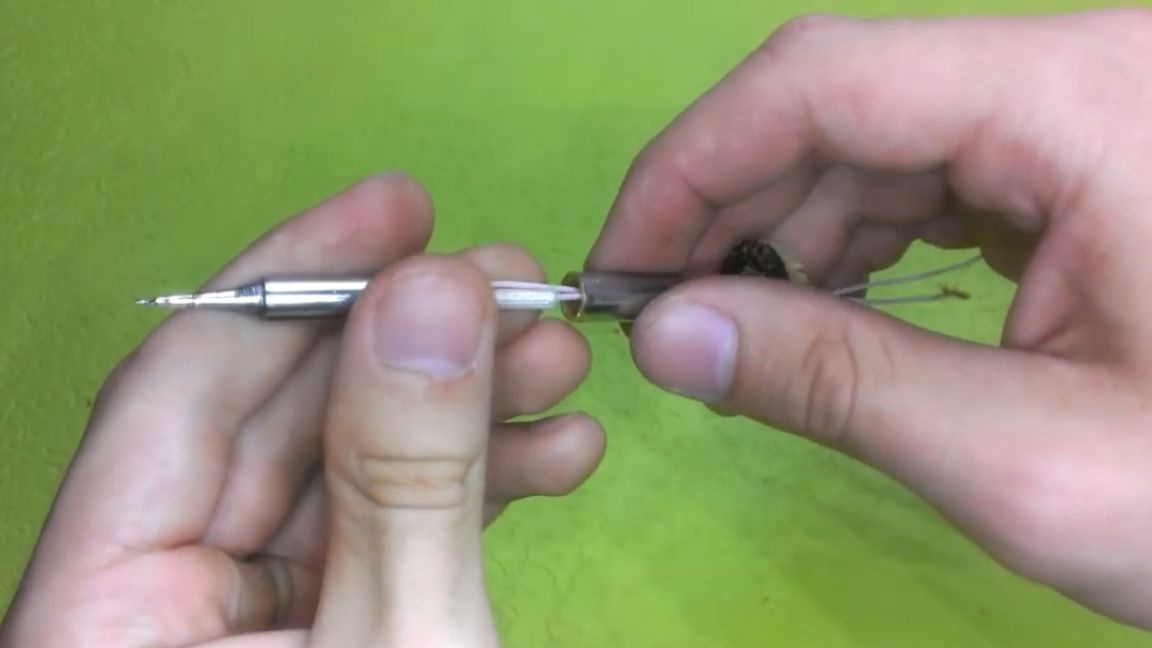
Now we will put together the parts of our soldering iron. First, connect the heater to the extension cord, then everything to the body, and then the battery.
Now let's get down to electronics. The device diagram is simple to disgrace, but you need to draw it, since beginners are unlikely to figure it out.
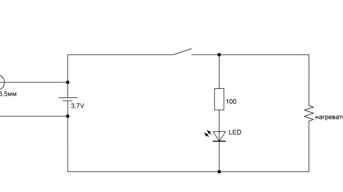
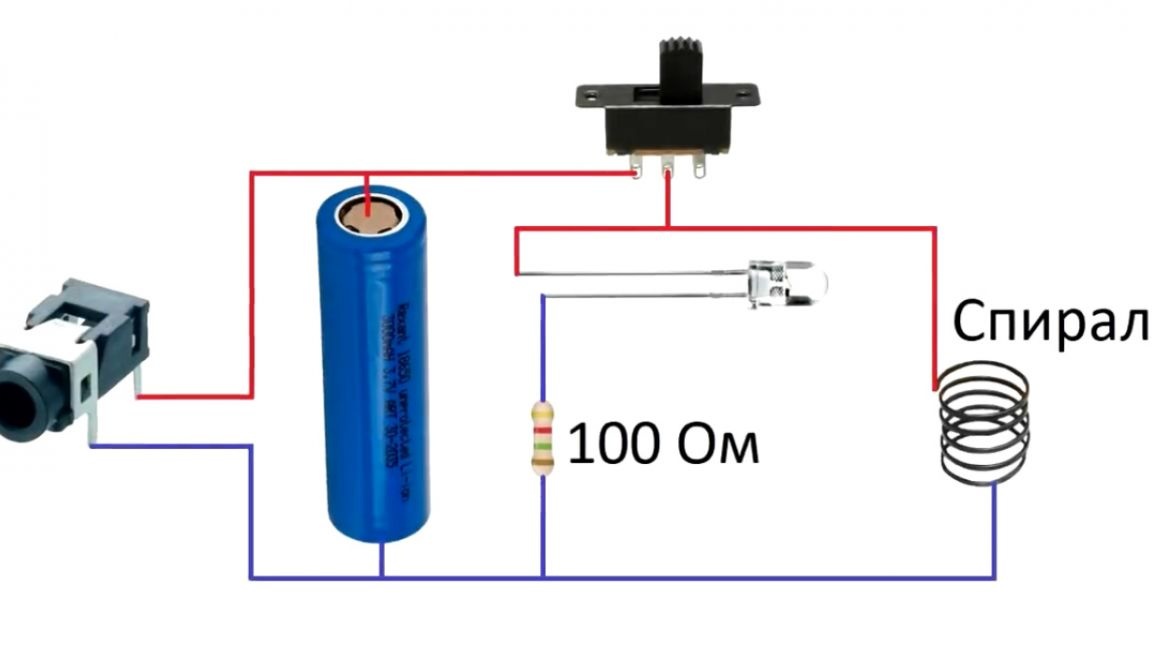
As you can see, there are no complex components, or transistors and microcircuits. Therefore, everything can be connected by a hinged installation. The author uses a 3.5 mm plug as a charging socket.
That's because he has a standard charging board installed in the power supply, and as you can see (if you saw previous videos from the author of the Open Frime TV channel), all the devices that he assembled are adapted for this charging. This solution is very convenient, you do not need to come up with a new one every time, it has already become for him as a GOST.
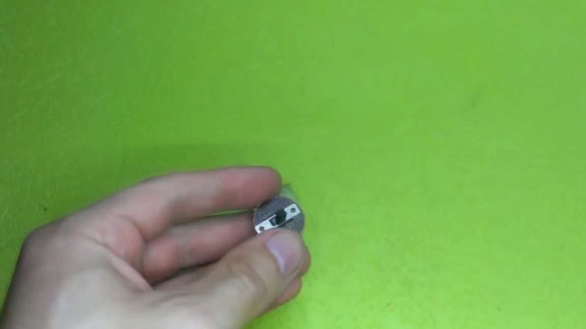
To install the electronics, you still need to make a couple of holes, namely for charging and an LED. And also close the top hole with another round of PCB. A switch will be mounted on it.
When everything is ready, you can assemble it in one piece. This is done very easily and everyone can repeat it.
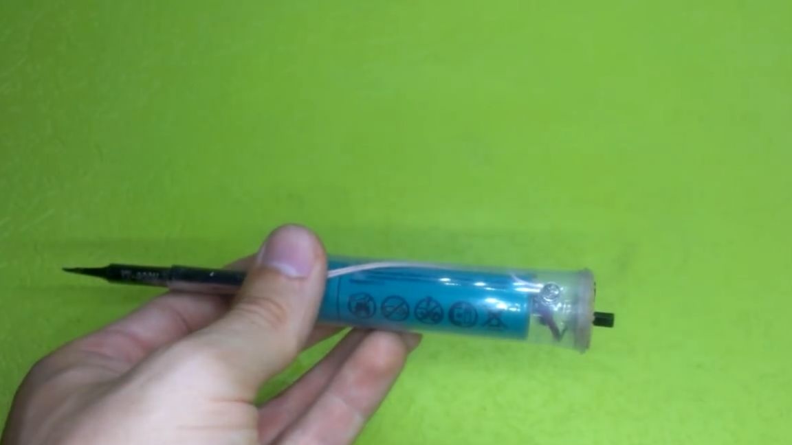
After assembly, the final appearance of the device does not suit the author, therefore, to give a presentation, he decided to paint the case in black.
Well, another thing is already similar to the factory design. As you can see, the whole manufacturing process took quite a lot of time, any other person would just buy a factory soldering iron.
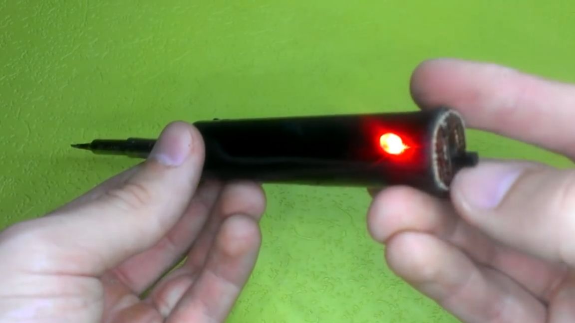
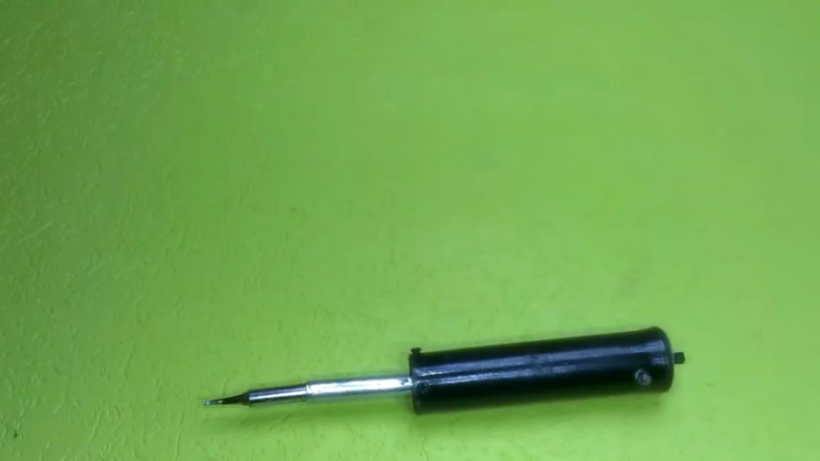
Now let's check what this soldering iron is capable of. To do this, we will conduct a couple of tests. To begin with, we can check how quickly it heats up. As you can see, the soldering iron is absolutely cold.
Now turn on the power, look at the timer. After 50 seconds, the soldering iron is ready for use, this is because the battery is a bit low.
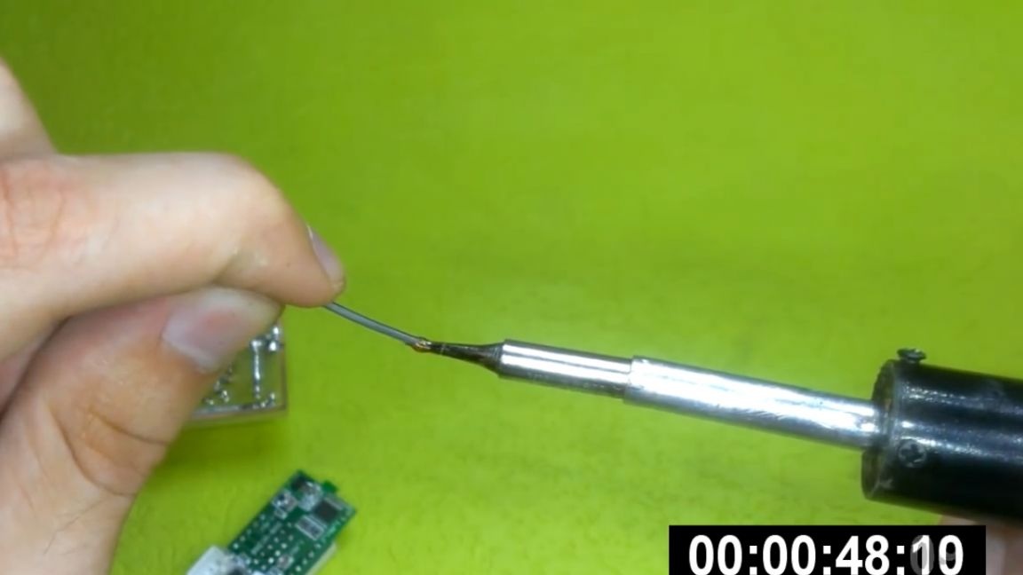
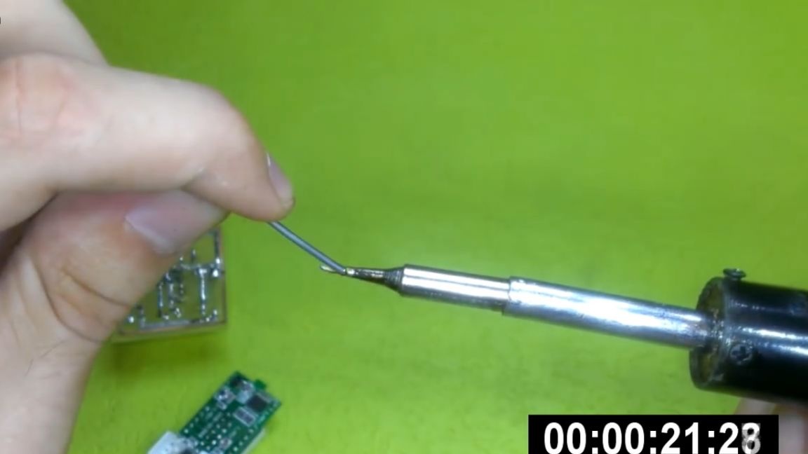
Now try to tear the wire.
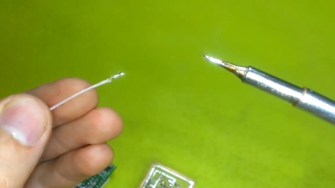
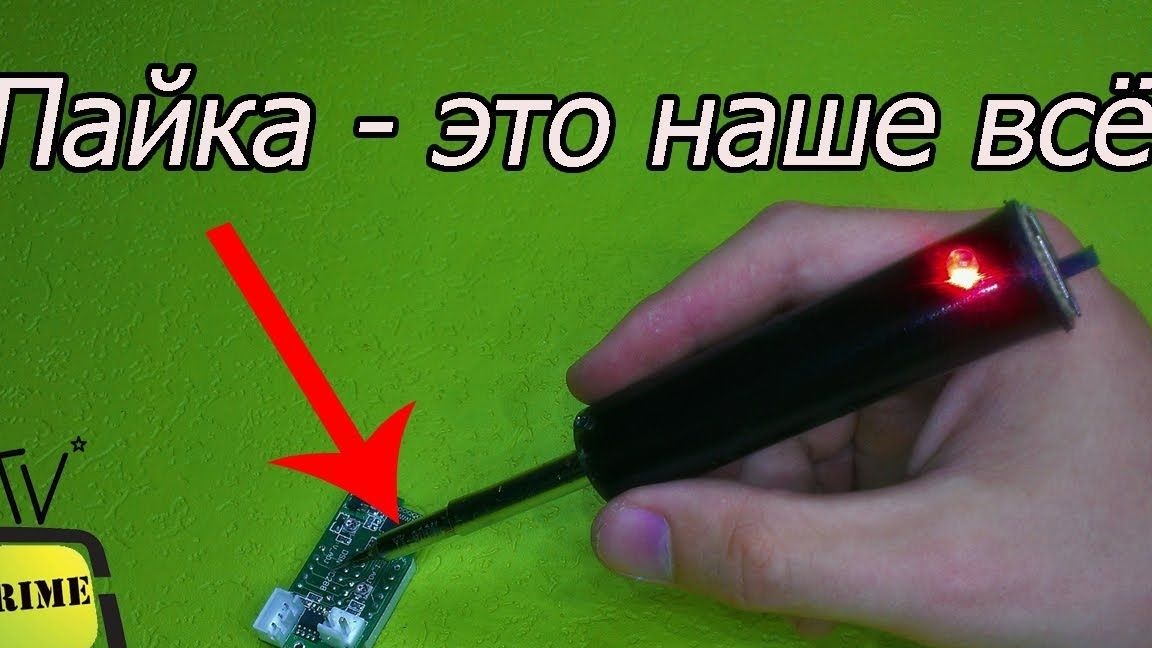
For our soldering iron - this is a kindergarten, coped without problems. Now solder it to the board.
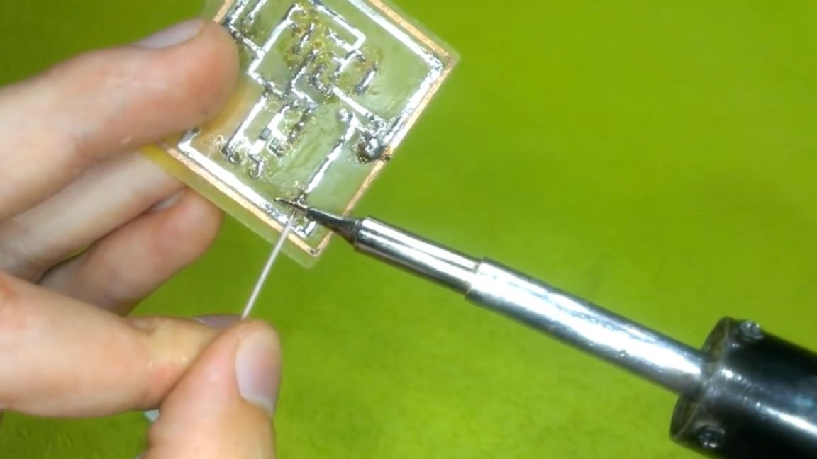
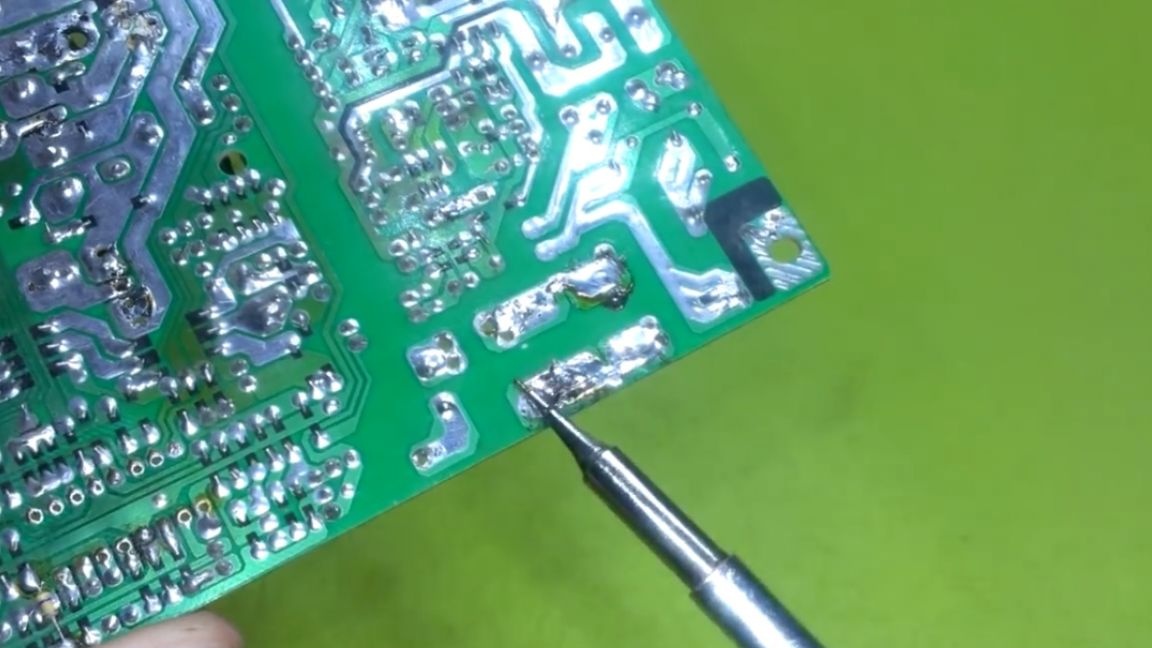
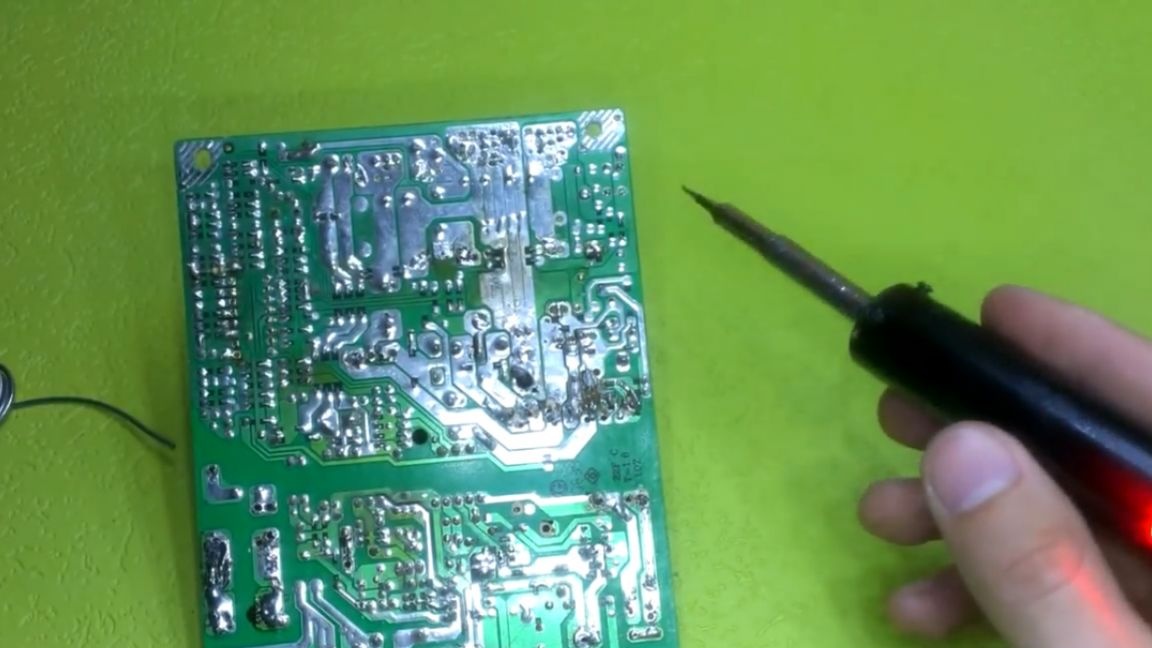
As we see, it solders perfectly.Let's repeat the test, but on a more heat-absorbing board from a computer power supply. Here the arrays of tracks will be larger, but our soldering iron warms them up for one or two.
In general, it is already clear that the soldering iron turned out to be excellent and fully justifies itself. That’s probably all. Thank you for attention. See you soon!
Video: