In this article, AKA KASYAN will show how to make a protective device for electrical appliances 220V.
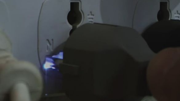
Any of you was faced with the fact that when you connect a household appliance to the network, a spark is formed in the outlet with a characteristic click.
If the device is too powerful, then even the formation of a voltage drop in the network is possible.
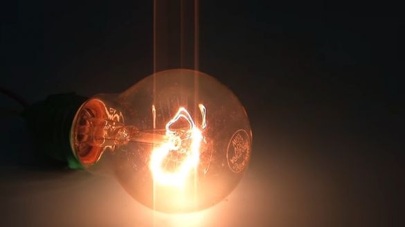
This was noticeable in the era of incandescent lamps, when the filament dimmed when starting, for example, a refrigerator or a grinder.
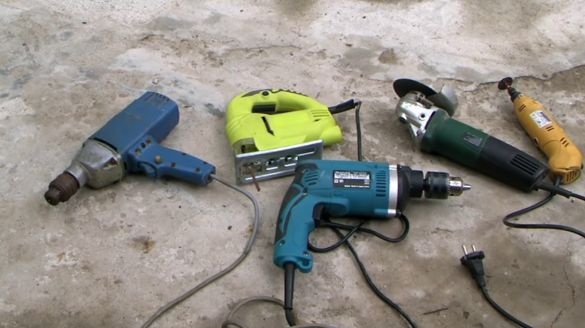
Power tools, power adapters of various devices, and most household appliances.
All of them, when connected to the network, at the very beginning, consume a very large current from the network for a very short time. It can be tens or even hundreds of times higher than their rated operating current.
This is called inrush current.
Very often, the engine of your washing machine or the power supply of your computer fails precisely because of this.
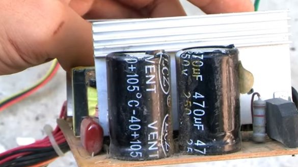
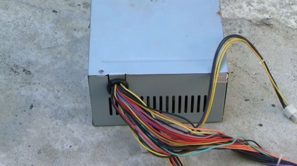
In switching power supplies there are capacitive capacitors, when you connect the power supply to the network, these capacitors are charged with colossal current, which must be limited, otherwise it will be bad.
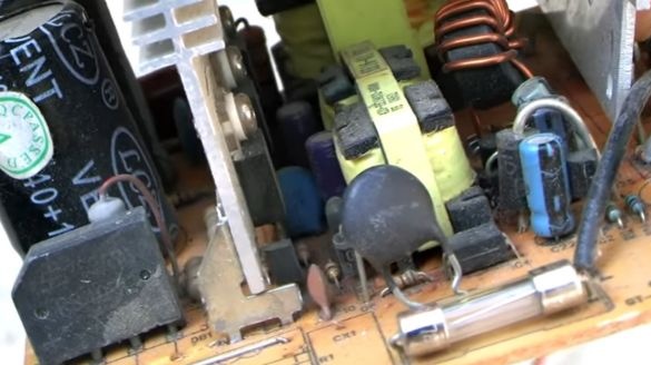
Of course, the manufacturer somehow limits the starting current by using thermistors.
But this is not always enough.
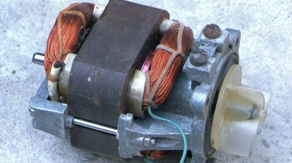
The same thing with the engine from the refrigerator, washing machine, electric drill and so on.
They also quite often use some system to mitigate the launch.
But given the fact that the modern market is designed for a fool, naturally, the quality of the components used in many devices is at a low level.
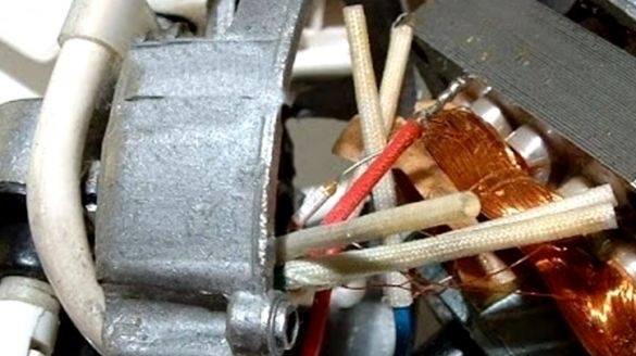
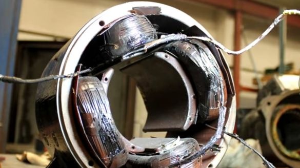
The thin wires used to wind the motor windings often burn out, unable to withstand high inrush currents.
Yes and electronics also not eternal thing.
Today we will consider a device that will help to significantly extend the life of any household device.
You now have an external softstarter.
This scheme provides a smooth start of the load with a delayed on.
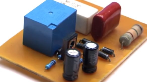
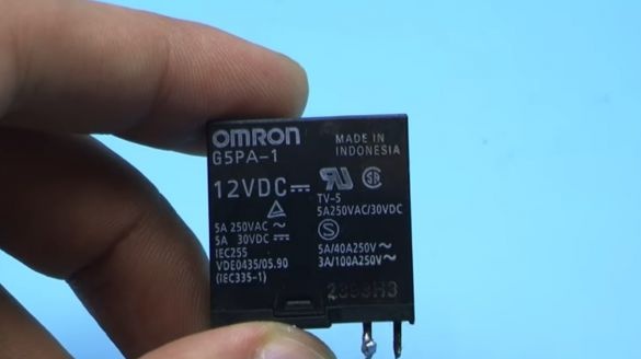
It is assembled based on a relay.
Yes, the relay contacts are not eternal, but they will last at least a few years.
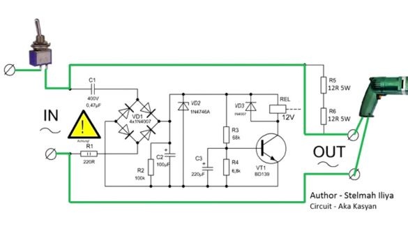
The input of the device through a switch is connected to a 220V network.
The output is connected to the load that needs to be protected.
Here it is necessary to note the following point.
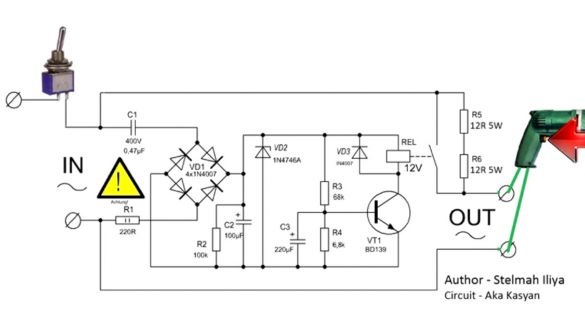
If you are going to use this system for smooth start-up of power tools, then you need to use the button on the tool itself as a switch. It is important.
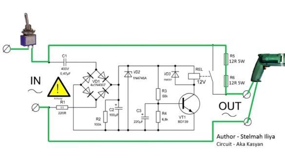
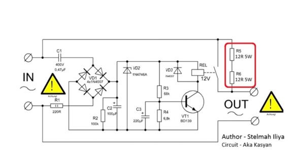
When the switch closes, the mains power, through powerful current-limiting resistors, is supplied to the load. For example, an electric drill.
These resistors themselves limit the current, and the drill starts smoothly without jerks and power surges.
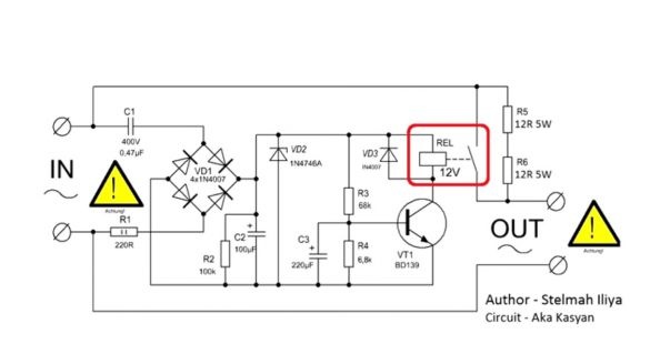
After a while, the delay system is activated, and the relay closes.
Now the power to the load is supplied through the relay contacts, bypassing the resistors.
By that time, our drill was already working, though it was not spinning at full capacity.
And now, after the relay is triggered, it receives the full voltage from the network.
In other words, we slightly twisted the drill with a weak voltage, thereby eliminating a large inrush current, then applied the full voltage, that's all.
The same will happen if a computer power supply is connected through this device.
First, the capacitors built into the power supply will smoothly charge through the resistors.
As soon as they are charged, the relay will trip and the full supply voltage will come.
And since the capacitors are already charged, a large inrush current is eliminated.
Consider the ongoing processes in more detail.
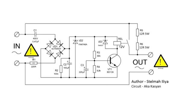
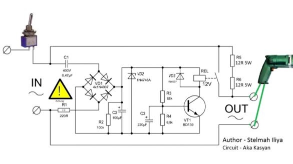
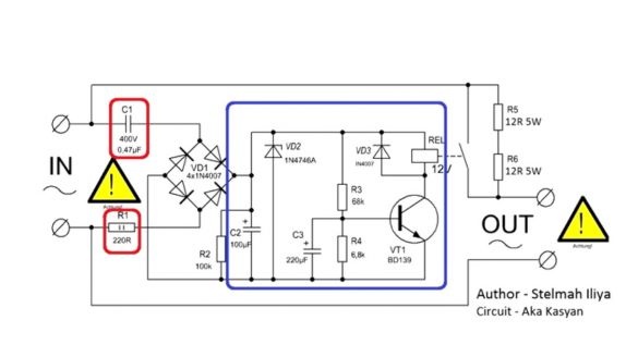
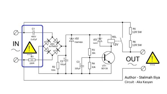
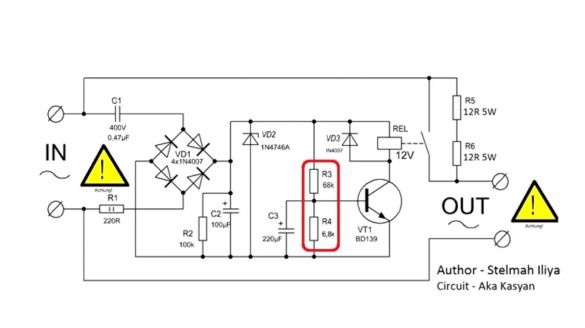
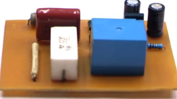
When the circuit is connected to the network, power is initially supplied to the load through the limiting resistors R5, R6. At the same time, the mains voltage, through the limiting resistor R1 and the ballast capacitor C1, is supplied to the on-delay circuit.
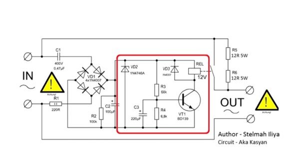
This part of the circuit is a simple transformerless power source.
The output current of the circuit depends on the capacitance of the capacitor. Next, the voltage is rectified by the bridge VD1 and smoothed by the capacitor C2, in parallel with which the Zener diode VD2 and the high-resistance resistor R2 are connected.
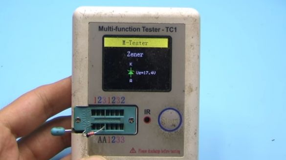
The zener diode limits the output voltage to 18 V, extinguishes all unnecessary on itself.
A resistor discharges the capacitor after disconnecting the circuit from the 220V network, providing quick opening of the relay contacts.
A voltage divider is assembled on these resistors.
Through the upper resistor R3, the delay capacitor C3 is smoothly charged.
And when it reaches a voltage sufficient to unlock the transistor VT1, the latter will work by supplying power to the relay coil. As a result, the relay will also work, the contacts will close, and the power supply from the 220V network, bypassing the powerful resistors, will go to the main load.
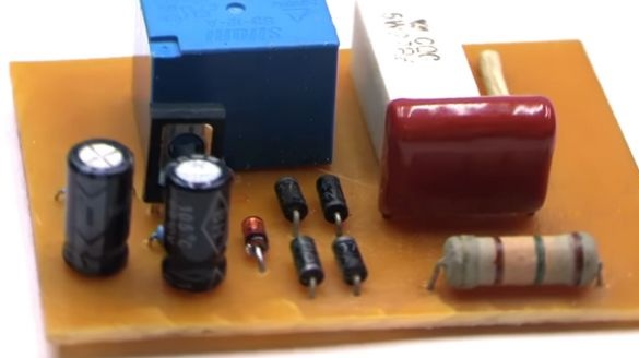
The VD3 diode, connected in parallel with the relay coil, is designed to protect the transistor.
Since when the relay opens, the self-induction voltage from the coil can break through the transition of the transistor.
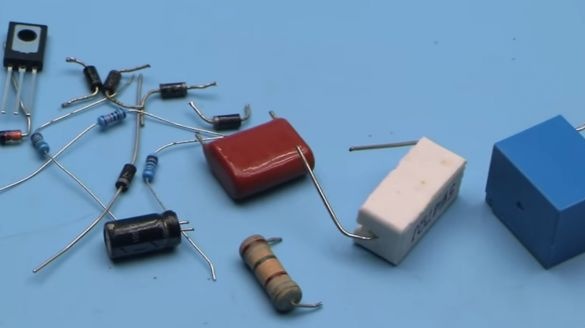
Let's talk about the components.
Resistor R1 at 220 Ohm, in principle, can be excluded from the circuit, replacing it with a jumper.
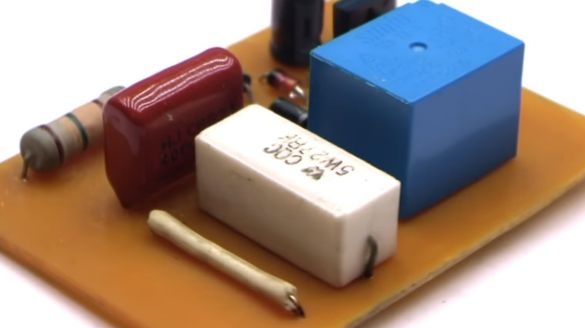
A film capacitor C1, with a voltage of 250-400 V with a capacity of 0.33 to 1 μF.
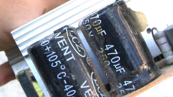
Electrolytic capacitors C2 and C3 must be taken with a voltage of 25-35V
The first capacitor C2 is used as a power filter, and its capacitance can be from 47 to 470 μF.
The delay time of the relay operation depends on the capacity of the second capacitor C3. The larger the capacity, the greater the delay and vice versa.
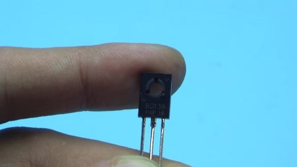
A transistor of almost any reverse conductivity, with a collector current of 1 A or more, costs BD139 in the circuit.
Zener diode with a power of 1W, stabilization voltage from 12 to 24V.
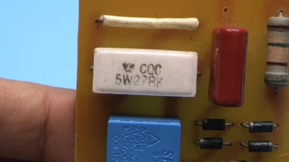
The limiting resistors R5 and R6 can have a resistance of 10 to 33 Ohms and a power of 5W.
It is advisable to take 15-20ohm.
Current limiting circuits can be calculated according to Ohm's law.
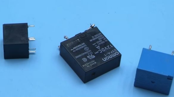
Relays with a 12 V coil. The relay current depends on your needs.
If you use a good relay, for example at 10A, then loads with a capacity of about two kilowatts can be connected to the circuit.
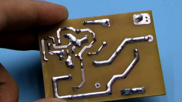
The power paths on the printed circuit board must be strengthened with solder.
Project submitted by AKA KASYAN.
All good homemade!

